

ADEMCO 678 Installation Instructions Manual
No. 678
DIGITAL
COMMUNICATOR
GENERAL INFORMATION:
The 678 is an 8 channel digital communicator that transmits coded messages over
,the telephone system to a digital receiver located at a central monitoring station.
Special leased lines are not required.
(There is a 9th channel dedicated to user
test and optional low ba=y reporting.)
To accommodate various receivers,
the 678 can transmit in three formats: I) Ademco
(and Silent Knight), 2) Ademco High Speed or 3) Sescoa/Franklin/DCI.
The 678 consi sts of a printed ci rcuit board chassis Bnd cover that may be in&a I led
in any suitable enclosure,
such as the Nos. 204 or 205 Cabinets, or the lower
section of a No: 1023 or 1024 Alarm Processing Center’s cabinet. (Note: The upper
section of a No. 1023 or 1024’s cabinet may be used as well, if the 678 is mounted
behind or in lieu of the APC’s normal control chassis.)
The 678 may be powered from a 6 or 12V. DC, filtered rechargeable, source [such as
(for 6V): Ademco Nos. 492, 493-j. Caution:
The Nos. 89 and 89-12 Energy Packs may
not be used, nor may sources containing Ni-Cad batteries such as the Nos. 96, 97,
497. A comnon power supply from a control panel can be used, even with bells connected
to the control (No. 1026 or 1028 series Alarm Processing Centers may not be used, as they
conta i n ‘N i-Cad standby batteries 1.
The 678 may be triggered by:
I) Application (or removal) of 6-l2V. DC supplied from
any alarm control (or other DC source), 2) Dry contact closure, 3) Dry contact
opening.
The 678 is easily programmed by the insertion of a PROM (Programmable ReadgnlY &emorYj
Chip, such as the No. 691. PROM Chips can be programmed bv Ademco or (with the No. 690
Programmer) by the i nstal ler.
The 678 has built-in line seizure and telephone line surge arrestors. Line seizure
automatically disconnects all telephones in ttie premises on the same line with the
communicator whenever the 678 is activated, to insure transmission without interruption.
Surge arrestors help protect the 678 from’voltage surges on the telephone line.
The 678 is compatible with the Ademco family of ancillary communicator accessories,
including the following:
Cat. No.
Description
620’
Di rect Connect Cord
659
Line Fault Monitor
664
Digital Communicator Tester
674
Select-A-Line (two line select module)
675
Ground Start Module
676/677
Listen-in System
684
Remote Command Tone Responder
688
Opening/Closing Switching Module
689
AC Power/Telephone Line Fault Monitor
826 I
Remote Buzzer
179
173
www.PDF-Zoo.com

OPERATION:
When a channel is activated; transm
as follows:
.
iss
ion to the central monitoring station occurs
,
I. After the normal 150 millisecond response time (or I6 seconds delay if
so programmed) the 678 executes line seizure and forces .a 1.6 second
hang-up to insure a disconnect if an outqoinq call was beina made.
@: The 678 has a built-in ACTIVATION LED which lights wh&ever the
unit is activated.
2. Next, the 678 checks for dial tone.
To shorten the time required for
contacting the central monitoring station, the 678 can sense internal
dial tone as well as external (telephone company) dial tone’.
3. If dial tone is detected, the 678 immediately and automatically dials the
preprogrammed telephone number, which can consist of up to 4 access digits
and up to I2 digits in the main (telephone company) number. Two telephone
numbers can be programmed and dialed as explained in PROGRAMMING OPTiONS.
Furthermore, the 678 can be programmed to dial “touch tone” in I ieu of
the slower “pulse dial” method.
The probability of immediate dial tone detection is high, but ff a
dial
tone
is not detected within II seconds, (.30 seconds, if so programmed), the 678
wi India I anyway,
on the assumption that the connection may be good even
though the dial’ tone is not clear.
4. W.hen connection is-made with the central monitoring receiver, a “handshake”
tone (acknowledgment) is sent over the telephone lines by the receiver to
the 678. This “handshake” confirms,
to the 678, that connection has been
camp leted to the r’ece i ver.
I f “handshake”
is not received within 30 seconds (60 seconds if so programmed),
the communicator will disconnect itself from the telephone line. After
waiting long enough (approximately 30 seconds) to disconnect any outgoing or
incoming calls which might interfere with diali-ng (“anti-jam” which only
works in “called party’ control exchanges), the 678 will reconnect to the
telephone I i ne, and again seize the line,
check for dial tone and dial
as described in Steps I, 2 and 3.
If necessary the 678 wi I I make up to a total of 8 attempts* (or “Unl imited
Attempts”,
if so programmed) to reach the central monitoring station via
primary and/or secondary programmed telephone numbers. See PROGRAMMING OPTIONS.
5. Upon receipt of the “handshake” (acknowledgment) tone, the 678 will start
transmitting its message(s), each consisting of a subscriber identification
number and a I digit alarm code corresponding to the number of the channel
that tri ggered.
Since faulty phone lines can distort the numbers, the 678 sends each message
up to 4 times while the receiver compares each message with the one before
it. As soon as the Receiver detects 2 successive identical messages, it
considers the transmission “valid” and sends a “kiss-off” code to the
Communicator.
l f more than one channe I has triggered,
the triggered channels will report
in order of ‘priority (i.e.:
low alarm numbers first) unless subsequent
channels trigger while one or more channels have commenced transmission.
Each channel message must receive
“kisgS~ff” before the next is sent.
174
www.PDF-Zoo.com
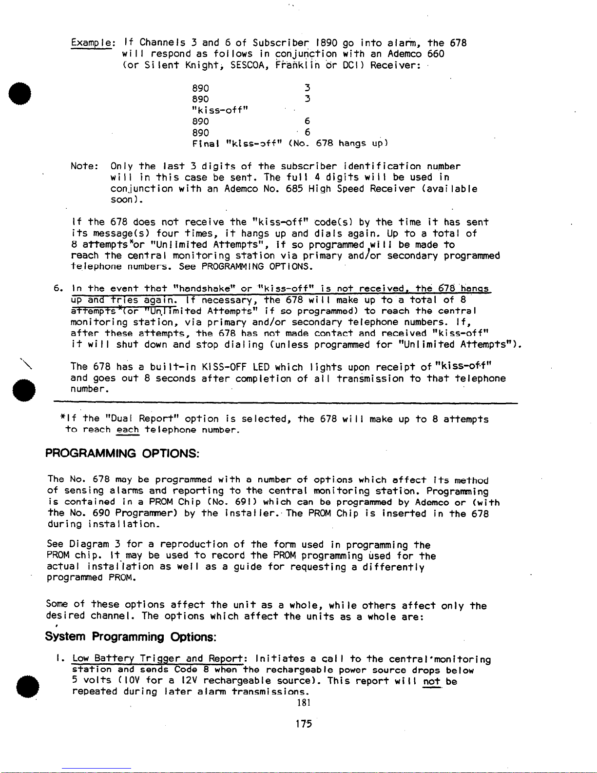
Example: If Channels 3 and G of Subscriber 1890 go into alarm, the 678
will respond as follows in conjunction with an Ademco 660
(or Silent Knight; SESCOA, Frahkiin or DCI) Receiver:
890
3
890 3
“kiss-off”
890 6
890 6
Final “kiss-sff” (No. 678 hangs up)
Note : Only the last 3 digits of the subscriber identification number
will in this case be sent. The full 4 digits will be used in
conjunction with an Ademco No. 685 High Speed Receiver (available
soon).
If the 678 does not receive the “kiss-off” code(s) by the time it has sent
its message(s) four times,
it hangs up and dials again. Up to a total of
8 attempts *or “Un I i m i ted Attempts”,
if so programmed wi I I be made to
reach the central monitoring station via primary and/or secondary programmed
telephone numbers. See PROGRAMMING OPTIONS.
.
6. In the event that “handshake” or “‘kiss-off” is not received’ the 678 ‘hanqs
up and tries agaln.
I f necessary, the 678 wi I I make up to a tota I of 8
aTtempts “(or “Un.1 imi ted Attempts”
if so programmed) to reach the centra I
monitoring station,
via primary and/or secondary telephone numbers. If,
after these attempts, the 678 has not made contact and received “kiss-off”
it will shut down and stop dialing (unless programmed for “Unlimited Attempts”).
The 678 has a built-in KISS-OFF LED which lights upon receipt
of”kiss-of-f”
and goes out 8 seconds after completion of all transmission to that telephone
number.
*If the “Dual Report” option is selected,
the 678 will make up to 8 attempts
to reach each telephone number.
PROGRAMMING OPTIONS:
The No. 678 may be programmed with a number of opti.ons which affect its method
of sensing alarms and reporting to the central monitoring station. Programing
is contained in a PROM Chip (No. 691) which can be programmed by Ademco or (with
the No. 690 Programmer) by the instaIIer:The PROM Chip is inserted in the 678
during installation.
See Diagram 3 for a reproduction of the form used in programming the
PROM chip. It- may be used to record the PROM programming used for the
actual installation as well as a guide for requesting a differently
programmed PROM.
Some of these options affect the unit as a whole,
while others affect only the
desired channel. The options which affect the units as a whole are:
&tern Programming
Options:
I. Low Battery Trigger and Report: Initiates a call to the ten
station and sends Code 8 when the rechargeable power source
5 volts (IOV for a l2V rechargeable source). This report wi
repeated during later alann transmissions.
181
tral’monitoring
drops be I ow
I I not be
-.
175
www.PDF-Zoo.com
2.
3.
4.
5.
6.
7’.
8.
Dua I Report:
Reports all information to the second, telephone number after
receiving kissoff from the receiver at the primary number. In the event
that 8 attempts are made, but no “kiss-off”
is received from the primary
number, the No. 678 will then make 8 more’attempts to report to the
secondary number.
c-3
:, ,:
Note: When Dua I Report is’ used,
xbe programmed.
Unlimited Attempts (System Option 7)should
Alternate by Pairs:
The dialer will’attempt to fall the primary number
twice, then, if “kiss-off” has not been received, it will make two
attempts to reach the receiver at the secondary number. It w i I I a I ternate
by pai rs of ca I Is unti I a tota I of 8 attempts have been camp leted, or
” ki s&off”
is received.
Extended Acknowledge Wait:
Doubles the acknowledgment wait period from
30 seconds to 60 seconds. Helpful on phone networks with long switching
time.
Extended Dial Tone Wait: Triples the dial tone waiting period from II seconds
to 30 seconds. IJseful in slow dial tone areas.
Touch Tone Dia I : Instructs the communicator to dial touch tone instead of
the slower pulse dial method.
Unlimited Attempts: Causes the 678 to continue making attempts to reach
the receiver until “kiss-off” 1s received, rather than ceasing after 8 attempts.
Note:
Unlimited Attempts should not be programmed when Dual Report (System
won 2) is used.
SESCOA: Causes the No. 678 to look for the SESCOA/Franklin/DCI acknowledge
and acknowledge hold signals and to report in SESCOA format. If this option
:r--)
is not selected, the No. 678 will respond in the Ademco standard format.
‘,.
For,Ademco hi-speed format see instructions accompanying the No. 685 Receiver.
Channel Programming Options:
In addition to the system options, there are a number of options which can be
selected and which affect only those channels which the user desires. These are:
I. Long De lay Channels: Any number of channels may be programmed for a I6
second delay. Thus, the.nonal 150 millisec response time can be extended
to 16 seconds to minimize false triggering due to transients.
2. Open/Close Channels:
Channels selected as Open/Close Channels will report
when the triggering \;oItage appears as well as when the input voltage
is removed.
In order to transmit opening and closing rounds, the 678 must receive
signals when the control panel is armed and disarmed. These signals
are available directly from the No.
1023 Al.arm Processing Center or
Nos. 1022, 1024, 1026 and 1028 Alarm Processing.Centers when used with
the No. 688 Opening/Closing Switching Module. The signal may be applied
to the 678 when the control i s armed and removed when the contra I is
disarmed, or vice versa.
With the standard Ademco or SESCOA format, an Open/Close Channel will
report the subscriber identification (the 3 last digits of the 4 digit
identification code contained in the PROM) followed by the number of
the channel when an input is applied to the channel.
182
176
c-3
. . ’
www.PDF-Zoo.com

When the input is removed,
an Open/Close Channel will report the subscriber
identification (3 last digits) followed by an alarm code 9. For example,
for subscriber No. 1890 the No. 678 will report:
890
9
890 9
“Ki ss-off “------hang up
If a channel is selected as both an Open/Close Channel and a Delay Channel,
the delay applies to the input being applied and the in- being removed.
Since Code?9 can also mean test, use caution.Tso since the channel is
not identified upon removal of input,
restrict’this method to one channel.
3. Restore,ChanneIs: Channels so designated will not only report when the input
voltage goes high (alarm) but will report again when the input voltage goes
low (restore). When the input goes high (alarm) the affected channel .wi II
report subscriber identification and channel number, to be followed by
“kiss-off”.
However,
when the input goes low, the channel, (if it is selected as a Restore
Channel) will report the subscriber identification followed by the channel
number; then, after “kiss-off”,
the 678 will report the subscriber identification
followed by code 9. For example, should channel 4 restore, the message
sequence wi I I be:
890
4
890
4
“kiss-off”
890
9
890
9
“kiss-off”------hang up
If, in addition to being selected as a Restore Channel, a channel is
selected as a Long (I6 set) Delay Channel, the.delay applies only to
the input going high (alarm). If the input goes low (restores), 150 msec
de lay app I ies. This feature permits the 678 to report a restore on the
same call. as it reports an alarm, thus reducing the frequency .with which . .
.‘a, i,:
emergency services will be notified in the event of false alarms.
4. Secondary Number Only Channels: Any channel or channels may be’selected
to call and report only to the secondary number. This feature can be
used to force openings and closings to call the secondary number, leaving
the primary number open for emergency cal Is, such as fire, holdup,
burglary, etc. This channel option takes precedence over the system
optlons of “Alternate by Pal&’ and “Dual Report”.
5. Inverted Channels: Any number of chanhels may be programmed for inverted
operation. This means that the mi croprocessor wi I I interpret the presence
of a voltage on that channel’s input terminal as normal (restored). The
absence of a voltage will then be treated ,as abnormal (alarm).
All alarm reporting and timing features described in channel options I to
3 (above) still apply, but with the reversed definition of normal and alarm.
Inverted operation can be used to obtain triggering upon dry contact opening
by hooking up the channel input as for dry closure, but substituting a
NC switch for the NO switch.
The ability to invert a channel also provides features not otherwise easily
a
available. For example, suppose it is desired to send opening and closing
information, but code 9 (see Channel Option 2) is found unacceptable. Suppose
183
177
www.PDF-Zoo.com
 Loading...