

ADEMCO 612 Installation Instructions Manual
MARGIN LINES IND I CATE PRINCIPAL CHANGES IN THIS
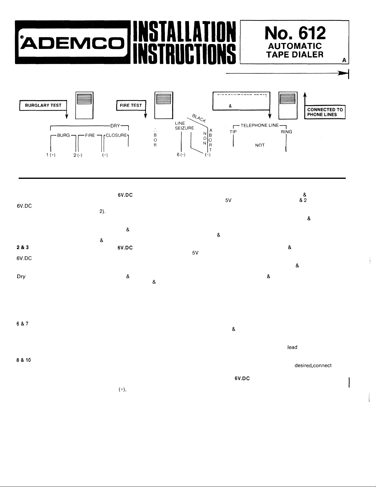
TEST SWITCHES DIALER
A
4/87
ISSUE
DISCONNECTED
PHONE LINES
TEST SPEAKER
FOR
FROM
0
TERMINALS
1&2
(Burglary,
Input)
1&4
(Burglary
or panic,
Dry Closure)
(Fire,
Input)
3&4
(Fire,
Closure)
5
(Abort)
(Line
Seizure)
7
(Non-Abort)
(Telephone
Line)
RED81BLACK
LEADS
(Power)
I
3
4
T
5
7
I
8 9
USED
0 0 0 0 0 0 0 0
OBSERVE
When a output is used to activate the burglary channel,
terminals of any Ademco cont rol. A n y voltage between
the dialer. Be sure t o OBSERVE PROPER POLA R I T Y : pos i t i v e
When a contact closure is usedtoactivate the burglary channel,
normally open device ,Any closure, either momentary (of at least
terminals 1
these terminals. If a 6V input is u sed onter minals
4.
When a input is usedto activate t he firechannel,
nals of the co ntr ol . Any voltage between and 14Vwill activat e the dialer. Be sureto OBSERVE
PROPER POLARITY: negative
Whenacontact closure is used to activate the fire channel,
mally open device. Any clo su re , either momentary (of at least
terminals 3 4 will activate the dialer.Ifa 6V input is use d on terminals 23,a contact closure cannot
be used onterminals 3
If
you wish to preven t(abort) the dialer from continuing to makeoutgoing calls once the local control or
-
in activating device has been restored to normal,
lock
terminal 7
automatically disconnected from the telephone line and no further calls will be made. Once the dialer has
RESET,
quent alarm.
If
possible inte rrup tion of the message) connect terminals 6
620
If
operated by a momentary contact device, leave the spade lug of th e BLACK flyin g
terminal 7.
Connect terminals 8 (TIP) and 10(RING) to the telephone line,
regulations permit,
a
Connect ONLYto a 6V battery or an Ademco rechargeable filtered power supply
96, 487 or 497).The Ademco
positive
it
lineseizureisdesired
Direct Connect Cord is used toconnect to telephone line and handsets. See N o . 620's instructions.
you wish the dialer to complete all of itscalls,ev e nifthe activating device is RESET,
No.
663Line Seizure Module
POLARITY
4 will activate the dialer. Devices f or 24-hour hold-up or emergency protection should us e
to
terminal5.The dialer will then continue to run until it is completely RESET, but will be
will be automatically reconnected to the telephone line an d will beready to report a subse
via a standard four pin plug or directlytothe line. If line seizure is via
black lead tonegative
WHEREVER
(-)
to terminal 2, positive+)to terminal 3.
4.
(disconnects all telephones fro m t he line when the dialer is acti va ted , to prevent
and
No.
620 (see
No.
89 E ner gy Pack may
(-).
NOTED
1
No.
ABOVE
connect dialer terminals 1 2t o the bell
and 14Vtodialer terminals 1will activate
(+)
to
terminal 1, negative
connect dialer terminals 14 to any
0.5
seconds durati on) or lock-in, across
2,a contact closure cannot b e used on terminals 1
connect dialer terminals 2 3tothe bell termi
connect dialer terminals 3 4 t o any nor
0.5
seconds dur atio n) o r l o c k-in, across
move the spade lug on th e B L A C K flyin g leadfrom
7
toa
No.
663 Line Seizure Module. A No.
via a
No.
620 Direct Cord, or,
620's instructions).
not
be used. OBSERVE POLARITY: red lead to
10
0
or if t h e dialer is
connected
(suggested:
(-)
to terminal
when local
-
-
-
to
Nos.
GREEN LEAD
(Ground)
For protection of the circuitry against telephone line induced tran sients,
(A cold water pipe or electrical box may be used in some locations.)
Additional transientp rotectio n can be provided by a No.255 Lightning Protector
acrossthe telephone line and to ground.
A No.663used for linese izur e also provides transient protection for the No. 612
completely from the telephone line. In this case, a
entering the
No.
663 for protection of the
Nos.
No.
255 may be installed across the telephone line
663
and
612.
connect to a good ear th gr ound.
which connects di re ct ly
by isolating its circu it ry
OPERATING
1.
To
Test The Dialer
A. Slide the switch marked “DIALER” (above terminal
NECTS
IMPORTANT:
8.
Test
C.
When test is completed and tape automatically resets, the dialer will stop and the pilot light will go off.
IMPORTANT:
FOR
NORMAL OPERATION,
2.
Fire Channel will overr’de Burglary Channel in the event bath are tripped during alarm condition.
3.
Dialer automatically resets after each alarm
NOTES:
PHONE
either channel (Fire
LINE.
THIS SWITCH MUST REMAIN IN
RETURN THE SWITCH TO THE UPPER POSITION UNTIL AFTER THE DIALER HAS
GONE
OUT,
RETURN “DIALER” SWITCH TO UPPER
LOWER POSITION, THE DIALER
MESSAGES WILL NOT BE SENT.
OR
or
Burglary)
THE
10) to the lower position. THIS
THE
LOWER POSITION FOR THE
YOU
WILL TRANSMIT ACTUAL ALARM MESSAGES.
by
holding appropriate “TEST” switch down for approximately
SWITCH
MARKED
or
abort condition.
POSITION
WILL
BE
“DIALER”
DtSCONNECTEO FROM
MUST
WHEN
ALWAYS
CONNECTS
TESTING
BE
IN
THE
ENTIRE
IS
COMPLETED. IF THE SWITCH IS LEFT
THE
PHONE LINE AND SUBSEQUENT ALARM
UPPER
INTERNAL SPEAKER AND DISCON
DURATION OF THE TEST. DO NOT
RESET
AND THE PILOT LAMP
one
second.
POSITION.
IN
-
HAS
THE
Outside
Here
fl----------
O-cScrew
Hole
Hole
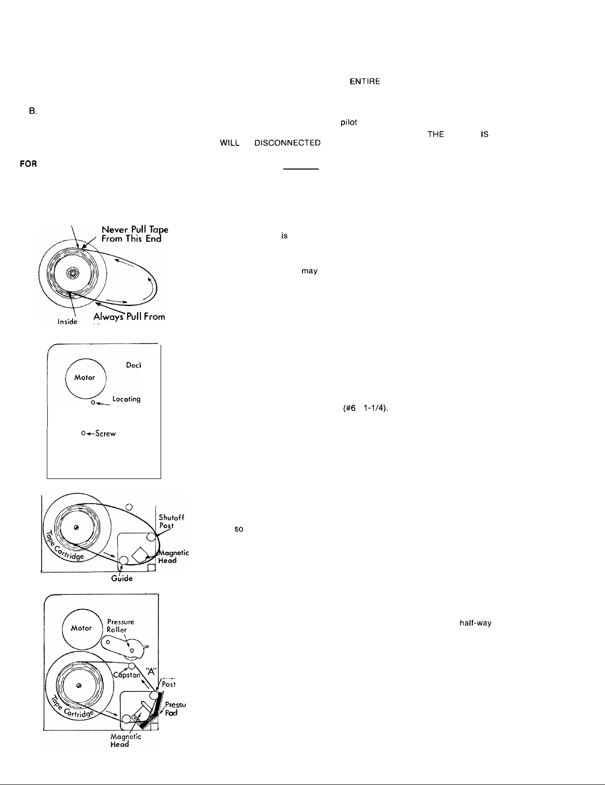
INSTALLATION OF
The tape cartridge
from the inside of the tape reel (bottom
of the cartridge). Slack in the exposed
the tape in its normal direction, always starting at the bottom of the cartridge. This is impor
tant
to
know since there may be slack in the tape loop
CAREFULLY REMOVE THE TAPE FROM THE PLASTIC BAG. DO NOT EXTEND THE
LOOP. Position the tape cartridge
the lock ring should be facing
pin under the reel fits into the locating hole. Now, by moving the cartridge slightly left or
right, look for the screw hole
it
in place using the screw supplied
THE TAPE
is
of special endless-loop design. This means that the tape always travels
up.
on
CARTRIDGE
of
the cartridge) to the outside of the tape reel (top
loop
can be automatically taken up simply by pulling
when
you
first install the cartridge.
on
the
deck, below the motor. The side
By rotating the cartridge, position it
the deck through the center hole
(#6
x
1-1/4).
of
the reel with
so
that the locating
of
the cartridge and fasten
-
GLide
Post
Shutoff
/Post
Taking care not
tridge
so
Gentiy lift the pressure roller, place the tape over the capstan
and return
against the posts and magnetic head.
“
re
to
that a
the
end up with too much slack, pull enough tape from the bottom of the car
loop
is
formed around
roller to hold the tape against the capstan. The tape should now
the
two
2
posts and the magnetic head,
about
half-way down the shaft
as
be
shown.
-
taut
 Loading...