

ADEMCO 5890 Installation Instructions Manual
N5987V2 5/98
®
No. 5890
PASSIVE INFRARED MOTION
DETECTOR/TRANSMITTER
INSTALLATION
INSTRUCTIONS
For use with QED control panels ONLY!
GENERAL INFORMATION
The 5890 Passive Infrared Motion
Detector/Transmitter is a battery-operated
wireless device intended for use as part of a
QED 5800 series wireless alarm system.
Designed for use in commercial and residential
installations, the 5890 is a wall-mounted unit
with a standard lens that provides wide-angle
protection up to a range of 40 feet (12m). For
best coverage, mount the detector so that the
likely direction of intruder motion is a cross the
pattern.
Two optional interchangeable lenses are
available for this detector – the 199PA Pet Alley
lens, and the 199LR Long Range lens (see
PROTECTION PATTERNS FOR OPTIONAL
LENSES
This document provides installation instructions
for the 5890, but the installer must be familiar
with the Installation Instructions for the QED
5800 Wireless Alarm System with which the
5890 is intended to be used.
FEATURES
• Wireless operation for fast installation.
• Dual element pyro-electric sensor provides
• Alternate polarity pulse count option offers
• Provision to turn LED on while walk testing
• Tampered cover – unit transmits message if
• Wall or corner mounting options.
• Optional Pet Alley and Long Range lenses
SYSTEM DESCRIPTION
Optical System: Uses efficiently designed
Fresnel lenses.
Radio Transmitter: The built-in transmitter
serves only as the communication link to the
alarm system's Receiver/Control, and can send
alarm, tamper, supervisory, and battery status
messages to the system's QED
receiver/control. The transmitter is not used for
detection purposes. Each detector has a unique
ID code permanently assigned at the factory.
This ID needs to be "enrolled" by the QED
control system at the time of installation. This
allows each detector used in the system to be
uniquely identified. The QED control must be
programmed to "enroll" the 5890 as an "RF"
type unit (i.e., supervised RF).
To conserve battery life during normal
operation, no more than one transmission
sequence will occur within a 3-minute period.
There is no such time restriction in "test" mode.
Alternate Polarity Pulse Count: Two jumperselectable detection response modes are
provided:
and
Count ON). With Pulse Count OFF, any
on last page).
positive protection while minimizing false
alarms.
greater stability in adverse environments.
(LED is turned off after testing).
cover is removed.
available.
Instant response
Alternate Polarity Pulse Count
(Pulse Count OFF)
(Pulse
detected change in infrared energy will trigger
an immediate alarm signal. This mode is
recommended when the detector is used to
monitor a narrow hallway where coverage is
provided by only a single zone.
Use the Pulse Count ON mode when the
detector is installed in areas where periodic
changes in infrared energy levels are normal
(for example, where forced air heating ducts are
present). In this mode, it requires at least two
detected changes in infrared energy within a
short period before an alarm will be triggered.
Important Note:
the Pulse Count mode, be sure to walk test the
unit in this mode.
If the detector is to be used in
SPECIFICATIONS
Coverage:
Standard Lens
199LR Lens
199PA Lens
Pulse Count: Installer-selectable On/Off link.
Detectable
Walk Rate: 0.5 – 5ft/sec (0.15 – 1.5m/sec).
Mtg. Height: 7ft nominal (2.1m), but may be
Walk Test
Indicator: Red LED with Test/Normal
Batteries: Two 3-volt Lithium batteries.
0perating
Temperature: 32°F – 122°F (0°C – 50°C)
Operating
Humidity: Up to 95% RH (max.), non-
Dimensions: 2-11/16"W x 5"H x 1-7/8"D
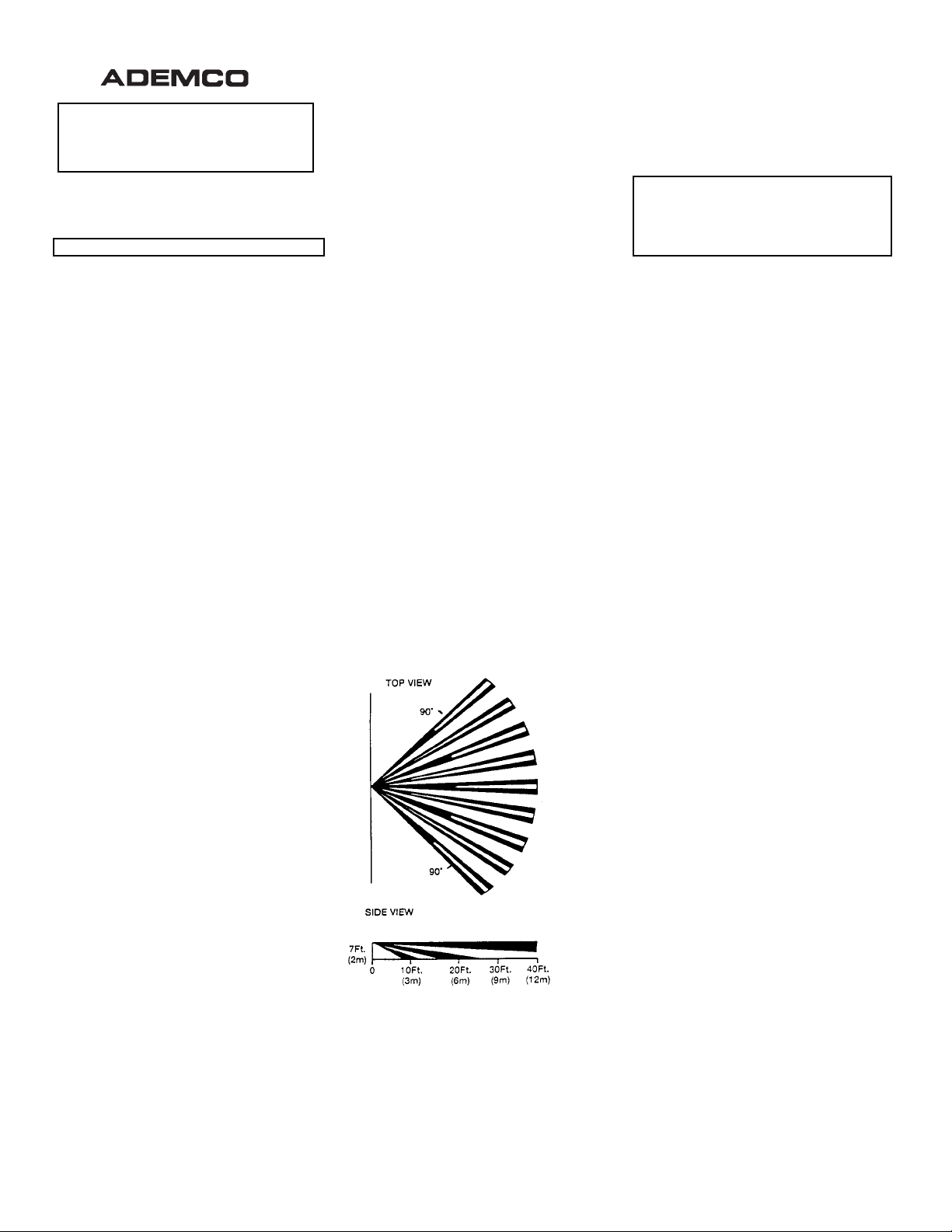
Standard Wide Angle Protection Pattern
: 40 ft x 56 ft (12 m x 17 m).
18 zones (9 long, 5 intermediate, 4 short range).
: 60 ft x 6 ft (18m x 1.8m).
5 zones (1 long, 2 inter
mediate, 2 short range).
: 40 ft x 60 ft (12m x 18m)
12 zones.
mounted at other heights (see
Table 1).
(disable) link.
Use only Ademco No. 466,
Duracell DL123A, Panasonic
CR123A, Sanyo CR123A, or
Varta CR123A.
condensing.
(68mm x 127mm x 48mm).
Figure 1.
BATTERY INSTALLATION
1. Remove front cover by inserting a large
screwdriver blade (or small coin) in groove
between cover and base at the location
shown in Figure 2; rotate blade to override
snap fit, then lift cover off.
2. Observing correct polarity, install the two
Lithium batteries (supplied) into the battery
holders, as shown in Figure. 5. Make sure
the batteries are firmly seated.
3. Replace the cover (snap fit).
Battery Caution:
Risk of fire, explosion and burns. Do not recharge,
disassemble, heat above 100°C, or incinerate.
Dispose of used batteries promptly. Keep away
from children.
Programming Note: If the detector’s ID has
not been programmed into the system (i.e.,
this is an initial detector installation), refer to
the
PROGRAMMING
perform the ID “enrolling” procedure before
mounting or testing the detector.
section below and
PROGRAMMING
The QED control system must “enroll” the
detector’s ID during installation of the system.
The QED control should be programmed to
enroll the 5890 as an “RF” type unit (i.e.,
supervised RF).
To program the detector, place the LED jumper
in the TEST position (see Fig. 5), the Pulse
Count jumper in the OFF position, batteries
installed, and cover on. Temporarily cover the
lens (a cloth will do) to prevent any activation by
the detector.
When prompted for the device’s serial number,
you may either manually enter it or transmit
from the unit (remove the cloth cover and
motion your hand over the lens to activate the
detector, press the tamper switch, etc.).
to the QED control panel installation
instructions for programming details.
Return LED jumper to the NORMAL position
after it is enrolled in the control.
Refer
INSTALLATION HINTS
¥
Do not install where the detector is exposed
to direct sunlight or directly above strong
sources of heat.
•
Make sure the detection area does not have
obstructions (curtains, screens, large pieces
of furniture, plants, etc.) which may block the
pattern of coverage.
•
Avoid locating a unit in areas which contain
objects likely to produce a rapid change in
temperature, such as central heating,
radiators or ducts (or heaters of any kind), air
conditioners, open flame, etc.
•
Do not mount on an unstable surface.
INSTALLATION
Radio Transmission Path Check
Verify that a strong transmission path between
the 5890 and the system's Receiver/Control
exists
before permanently mounting the
detector.
(described later) with the detector temporarily
mounted in its proposed location. The 5890 will
transmit when sensing motion (waving arm or
walking into area). Sometimes, moving the
detector only a few inches means the difference
between a strong and weak transmission path.
Experiment until you are satisfied that the
location provides the strongest transmission
path, while still being practical for the protection
pattern desired. This test also verifies that the
detector has been correctly programmed into
the system.
Normal Mounting
Mount the unit to a firm vertical surface (flat on
wall or in corner).
1. Remove front cover.
2. Temporarily loosen (do not remove) the
Do this by performing the
screw holding the PC board in the detector
base (see Fig. 5 for location of this screw).
Walk Test
1
The board can then be moved up or down
for access to the knockout mounting holes
in the base.
3. Refer to Figure 3 for location of knockout
holes in the base. Break out only those
holes required.
4. Mount the detector w ith screws, using the
selected mounting holes.
5. Before fully tightening the PC board holding
screw, make sure the board is positioned so
that the arrow is in line with the appropriate
setting on the graduated scale on the righthand side of the PC board (see Table 1,
and Fig. 5).
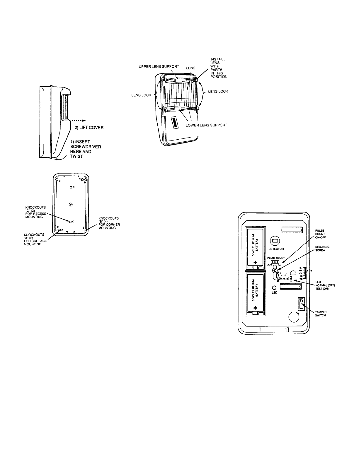
Figure 2. Cover Removal
Figure 3. Mounting Holes in Base
Recess Mounting
Recessed mounting requires the use of the
optional No. 1990MK Recess Mounting Kit.
Complete instructions for the use of this kit
accompany it.
base (accessible only when PC board is
removed) are used for recessed mounting.
Changing Lenses (if required)
1. Remove front cover.
2. Squeeze upper lens lock located in front
cover to release upper Fresnel lens support.
Squeeze lower lens lock to release lower
Fresnel lens support (see Fig. 4).
3. Note how the lens supports are positioned,
then remove the supports.
4. Carefully remove the existing lens and
replace with an optional coverage
replacement lens.
Note:
Holes "C" in the detector
The lens must be
installed with the smooth side facing
outward
.
Also, the lens should be oriented
with its part number on the upper right-hand
side (see Fig. 4).
lens.
Note:
Lens surface should be free of dirt,
foreign matter and finger-prints. Use a
clean dry soft cloth to wipe lens surfaces, if
required.
Be sure to center the
5. Replace top and bottom lens supports and
then press downward so that the lens locks
snap into position, thus securing the lens in
place.
6. Refer to Table 1 for recommended PIR
mounting height, pulse count setting, and
pattern setting for the lens in use.
7. Replace the front cover (make sure the
cover snaps tightly).
Figure 4. Changing Lenses
Vertical Pattern Adjustment
The protection pattern provided by the lens in
use can be raised or lowered by re-positioning
the PC board in the detector. A graduated scale
to the right of the board (see Fig. 5) indicates
the approximate number of degrees by which
the pattern can be raised (max. +5°) or lowered
(max. -15°). The detector is normally shipped
with the board set to the 0° position. To make
this adjustment, remove the cover on the
detector and loosen the screw holding the PC
board (the screw is located at the approximate
center of the board). Slide the board upward or
downward by the number of degrees required,
then tighten the holding screw again. After any
adjustment, you must conduct a walk test to
ensure proper coverage of the area to be
protected, as indicated under "Test
Procedures".
Lens Masking
The masking strips that have been supplied are
designed for application to one or more lens
segments to produce a protection pattern that
suits the particular requirements of the
protected area. Individual masking strips have
been provided for each of the lens segments on
the standard lens supplied with the PIR. Simply
peel off the appropriate pressure-sensitive
adhesive strip(s) and apply over the desired
lens segment(s). Be sure to affix the masking
strips to the
smooth side). Each lens segment that is
masked results in the elimination of one zone of
protection from the coverage pattern. By
masking segments of the lens, you can adjust
the coverage to suit the area to be protected, or
eliminate coverage from areas where you
anticipate environmental disturbances that
might reduce the PIR's stability (a heater or
other heat-producing object for example).
Important:
used, be sure the PIR is set for instant
response.
Horizontal Adjustment of Lens
The protection pattern provided by the lens can
e moved to the left or right by horizontal
adjustment of the lens, as follows:
inside
of the lens (not the outer,
When hallway pattern masking is
1. Remove front cover.
2. Press inward on the upper and lower lens
locks at the left or right side only to release
the lens supports on one side. Now slide the
lens to the left or right, as needed. The lens
may be moved as much as 8° (from center)
in either direction.
3. When the lens is in the desired position,
press the lens locks downward (on the
released side) to lock the supports in place.
4. Replace the front cover (make sure the
cover snaps tightly).
After any adjustment, you must conduct a walk
test to ensure proper coverage of the area to be
protected, as indicated under "Test
Procedures".
PULSE COUNT OPTION
Each detector includes Pulse Count circuitry
that is designed to provide stability in adverse
environments to minimize false alarms. Pulse
count is selected by positioning a jumper across
the ON pulse count terminals (shown in Figure
5). When set for pulse count, the detector will
signal an alarm within 2 or 3 steps, since the
processing logic requires more complex motion
than just a momentary event. When the
detector verifies an intrusion, the built-in
transmitter will send an alarm message to the
QED control/receiver.
LED DISABLE
The detector is shipped with the LED disabled
(LED jumper in the "NORMAL" position). The
LED may be enabled (for the "Walk-Test") by
positioning the LED jumper in the "TEST"
position (see Fig. 5).
Note:
When the jumper is in the "NORMAL"
position, the LED will not light, but the built-in
transmitter will transmit alarms when the PIR
senses motion.
Figure 5. PC Board
OPTIONAL LENSES
Two optional lenses are available which may be
used with the PIR. Information for these
lenses is provided in Table 1. Refer to
Changing Lenses
optional lenses is being installed in place of the
standard lens.
in this document if one of the
TEST PROCEDURES
Important: Testing should be conducted with
the protected area cleared of all people. Place
the protective system's QED control in the Test
mode
2
 Loading...