

ADEMCO 5869 Installation And Setup Manual
K5299V4 2/10 Rev. A
ADEMCO 5869
Holdup Switch/Transmitter
INSTALLATION AND SETUP GUIDE
GENERAL INFORMATION
The ADEMCO 5869 Holdup Switch/Transmitter is a fingeroperated RF transmitting device used for activating a
holdup signal at the security system control, and/or any
other security application. The 5869 is typically mounted
under a counter or money draw for inconspicuous operation.
When the transmitter is activated, it sends an RF signal to
the control panel, which then sends a burglary alarm to the
central station.
Once the 5869 trigger (Figure 1) is activated, the supplied
reset key K4563 must be used to reset the device. The 5869
also contains tamper switches that are activated either
when the cover is removed, or when the unit is forcibly
removed from its installation location.
The 5869 has a permanent serial number assigned during
manufacture used for enrolling the 5869 with the security
system control panel. To enroll the 5869, refer to the
respective Security System Control Panel Installation and
Setup Guide.
For certified UL installations, the 5869 must be used
with the 5881ENHC tamper-protected wireless
receiver, mounted inside its plastic enclosure and
outside the alarm panel enclosure.
PROGRAMMING
The 5869 Holdup Switch/Transmitter should be
programmed as a 24-hour silent zone type. Refer to the
Security System Control Panel Installation and Setup
Guide for programming instructions.
NOTES:
• During programming of the control panel, the 5869
Holdup Switch/Transmitter should be treated as "RF"
(i.e., supervised RF) Type.
• The 5869 is one closed input loop zone (loop 1).
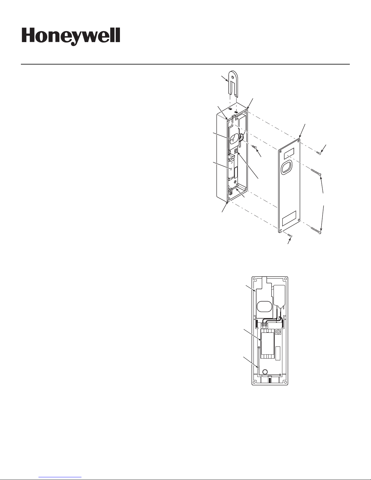
RESET
KEY
COVER
ATTACH
ANTENNA
HOLE
+
BREAKAWAY
TAMPER
SCREW
No. 6X3/4
COVER
TAMPER
SWITCH
COVER
SCREW (2)
No. 6X1/2
COVER
MOUNTING
HOLE
(TYP.)
TRIGGER
3V
LITHIUM
BATTERY
+
COVER
ATTACH
HOLE
Figure 1. 5869 Holdup Switch/Transmitter Details
TRIGGER
COVER
SCREW (2)
No. 6X1/2
MOUNTING
SCREW (2)
No. 6X2
5869-002-V1
MOUNTING
Mount the 5869 under a counter or money drawer for easy
access by the cashier. Refer to the figure and steps that
follow for typical mounting installation.
Before mounting the 5869 permanently, perform Go/No Go
tests to verify adequate transmitter signal strength at desired
mounting location (refer to the Security System Control
Panel Installation and Setup Guide).
1. Install the battery into the battery holder observing
correct polarity as shown in Figure 2.
2. Position the case to the desired location and install one
No. 6 x ¾ screw (supplied) at the breakaway tamper
release hole as shown in Figure 3.
3. Secure the cover to the case with the two screws (No 6 x
1/2) as shown in Figure 3.
IMPORTANT: To prevent damage to the case, do not
over tighten the cover screws.
4. Secure the case with the cover to its mounting location
using the two screws (No. 6 x 2) supplied as shown in
Figure 3.
3V LITHIUM
BATTERY
-
ANTENNA
NOTE:
THE NEGATIVE (
SIDE OF THE BATTERY
MUST FACE THE TRIGGER
Figure 2. 5869 Battery Installation
+
-
)
5869-006-V0
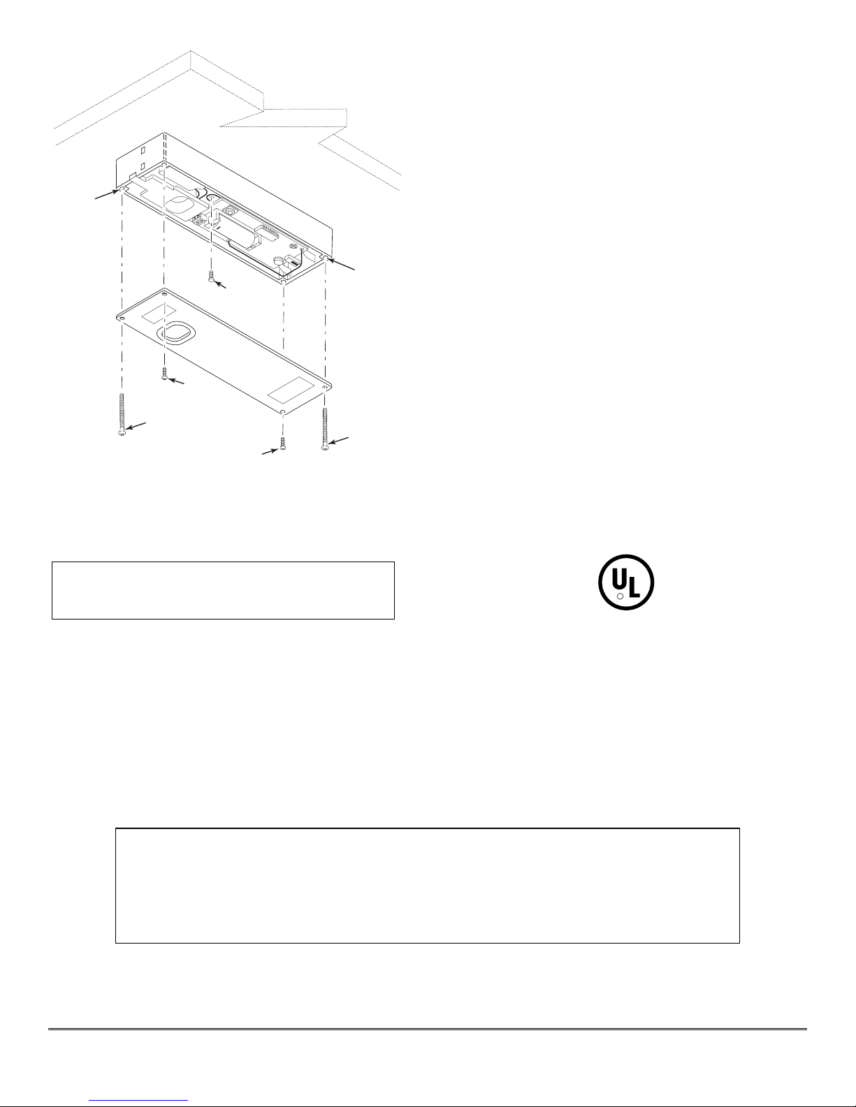
MOUNTING
HOLE
+
BREAKAWAY
+
TAMPER
SCREW
No. 6X3/4
MOUNTING
HOLE
2. Remove faulty battery and dispose of properly.
3. Observing correct polarity (negative side of the battery
facing the trigger), insert the battery into the battery
holder as shown in Figure 1.
4. Reinstall two cover screws and two mounting screws as
shown in Figure 1.
SPECIFICATIONS
Physical
Battery
Frequency
1-15/16"W x 5-15/16"H x 1-3/16"D
(50mm x 150mm x 30mm)
3-volt Lithium. ADEMCO 466, Duracell
DL123A, Panasonic CR123A, Varta CR123A.
345MHz
COVER
SCREW (2)
No. 6x1/2
MOUNTING
SCREW (2)
No. 6X2
COVER
SCREW (2)
No. 6x1/2
THIS DEVICE MUST BE PERMANENTLY
MOUNTED WITH THE SCREWS SUPPLIED.
IMPORTANT:
MOUNTING
SCREW (2)
No. 6X2
Figure 3. Typical Holdup Switch Installation
BATTERY REPLACEMENT
Risk of fire, explosion, and burns. Do not recharge, disas-
BATTERY CAUTION
semble, heat above 100°C, or incinerate. Dispose of used
batteries promptly and properly. Keep away from children.
IMPORTANT: When servicing the device for battery
replacement, note that with the mounting screws
removed the case is held in place by the tamper release
tab. Exercise caution not to jar the case while replacing
the battery, possibly breaking the Tamper breakaway
tab.
1. Remove the two screws securing the cover and two
mounting screws as shown in figure 1.
NOTE: Use care not to bend the antenna while
attempting to remove or install the battery.
:
5869-004-V0
Reset Key:
Agency:
Supplied, Part Number K4563 to order
separately
UL 636 – Holdup alarm units and systems
R
C
LISTED
US
Regular maintenance and inspection (at least annually) by the installer and frequent testing by the user are
vital to continuous satisfactory operation of any alarm system.
The installer should assume the responsibility of developing and offering a regular maintenance program to
the user, as well as acquainting the user with the proper operation and limitations of the alarm system and its
component parts. Recommendations must be included for a specific program of frequent testing (at least
weekly) to insure the system's operation at all times.
TO THE INSTALLER
- 2 -
 Loading...