

ADEMCO 5818 Installation Instructions Manual
EHEEEEl ;’:%%;%:
Previous Menu
For use with Q.E.D. control panels only.
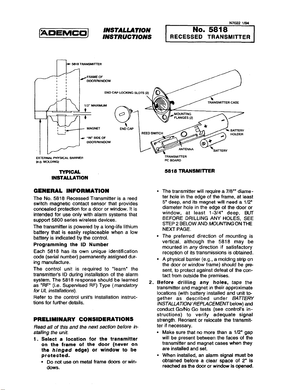
5slf3mANsMtl-rrm
r-L
,,
,,
1,
:’
1/2- MAXIMUM
t
4
1,
&
~ ,,IN” SIDE OF
END CAP LOCKING SLOTS {2)
MAGNET
DGOWWINOOW
N7022 1/94
fUO. 5818
RECESSED TRANSMITTER
o
0
01
~ +?N?:?2)
\
TRANSMITTER CASE
AT
E ‘~
EXTERNAL PHYSICAL BARRIER
(e.g. MOLDING)
TYPICAL
lNSTALLATfON
GENERAL INFORMATION
The No. 5818 Recessed Transmitter is a reed
switch magnetic contact sensor that provides
concealed protection foradoor or window. It is
intended for use only with alarm systems that
support 5800 series wireless devices.
The transmitter is powered by a long-life lithium
battery that is easily replaceable when a low
battery is indicated by the control.
Programming the ID Number
Each 5818 has its own unique identification
code (serial number) permanently assigned during manufacture.
The control unit is required to “learn” the
transmitter’s ID during installation of the alarm
system. The 5818 response should be learned
as ‘RFB (i.e. Supervised RF) Type (mandatory
for UL ir7sfa//ations).
Refer to the control unit’s installation instructions for further details.
PRELIMINARY CONSIDERATIONS
Read all of this and the next section before insta//ing the unit.
1. Select a location for the transmitter
on the frame of the door (never on
the hinged edge) or window to be
protected.
● Do not use on metal frame doors or win-
dows.
‘TRANSMl~ER
W BOARD
5818 TRANSMITTER
.
The transmitter will require a 7/W’ diameter hole in the edge of the frame, at least
5“ deep, and its magnet will need a 1/2”
diameter hole in the edge of the door or
window, at least 1-3/4- deep, BLJT
BEFORE DRILLING ANY HOLES, SEE
STEP 2 BELOW AND MOUN77NGON THE
NEXT PAGE.
●
The preferred direction of mounting is
vertical, although the 5818 may be
mounted in any direction if satisfactory
reception of its transmissions is obtained.
✎
A physical barrier (e.cj,, a molding stri~ on
the door or window f;ame) shou~ be”present, to protect against defeat of the contact from outside the premises.
2. Before drilling any holee, tape the
transmitter and magnet in their approximate
locations (with battery installed and unit together as described under BA77ERY
lNSTALLATIOIWREPIACEMENT below) and
conduct Go/No Go tests (see control’s instructions) to verify adequate signal
strength. Reorient or relocate the transmitter if necessary.
.
Make sure that no more than a 1/2’ gap
will be present between the faces of the
transmitter and magnet cases when they
are installed and set.
.
When installed, an alarm signal must be
obtained before a clear space of 2“ is
reached as the door or window is opened.
MOUNTING
1. Mark the selected location for the
transmitteron
or window.
2. Mark the Iocstion for the magnet on
the door or window, directfy opposite
the transmitter location.
Caution:
Drill holes at the locations marked,
3.
for the transmitter (7/8” diameter, at least 5“
deep) and magnet (1/2” diameter, at least
1-3/4 deep).
4.
Insert the transmitter and maanet
cases into their respective h;les,
so that their ends are flush with the surface.
● DO NOT hammer in place with hard blows.
● The transmitter case may be secured by
● if necessary, either case maybe secured
A closure plug is supplied to cover an empty
transmitter hole if it becomes necessary to relocate the transmitter.
Before drillina anv holes. make
sure that su;ces;ful Go;No Go
transmission/reception tests have
been conducted as called for in the
previous section.
If necessary, tap gently with a rubber
mallet or wood block.
two screws via the holes in its mounting
flanges, or the flanges can be snapped
off by scoring around them first with a
sharp knife.
with a suitable adhesive.
the frame of the door
BATTERY
iNSTALLATION/REPLAC~MEMT
Remove the transmitter’a end cap
1.
by inserting the fiat blade of a small screwdriver in the cap’s slot and turning slightly
counterclockwise.
2.
Slide the transmitter PC board assembly out of its case, taking care not
to bend the antenna during this step or later. -
3.
Remove the old battery, if replacing it.
4.
Observe correct pofarity and insert
the fresh battery into the battery holder
(+ and - polarity indications are inside). See
diagram.
5.
Slide the PC board assembly back
into its case, battery end first (the reed
switch end must be toward the cap).
6.
ReDtace the end cap. Line UDthe rxo-
je~ons on the cap with _theopenings at the
edge of the case, press the cap gently
against the PC board and turn the cap (via
its slot) slightly clockwise, thus locking it in
place.
BATTERY CAUTION: Risk of fire, explosion and burns. Do not recharge,
disassemble,
(lt)O°C) or incinerate. Dispose of
used batteries promptly. Keep away
from children.
heat above 2120F
SPECIFICATIONS
Dimensions (Approximate) Transmitted
Magnet IL? (13mm) Diameter, 1-3/4” (45mm) Long
Battery
Regular maintenance and inspection (at least annually) by the installer and frequent testing by the
user are vital to continuous satisfactory operation of any alarm system.
The installer should assume the responsibility of developing and offering a regular maintenance program to the user, as well as acquainting the user with the proper operation and limitations of the alarm
system and its component parts. Recommendations must be included for a specific program of fre-
quent testing (at least weekly) to insure the system’s operation at all times.
REFER TO THE INSTALLATION INSTRUCTIONS FOR THE RECEIVER/CONTROL
WITH WHICH THIS DEVfCE IS USED, FOR WARRANTY INFORMATION AND FOR
DETAILS REGARDING LIMITATIONS OF THE ENTIRE ALARM SYSTEM.
3V Lithium. Replace battery only with:
Panasonic CR1 23A, Duracefl DL123A, Sanyo CR1 23A, or Ademco 466.
TO THE INSTALLER
ALARM DEVICE MANUFACTURING COMPANY
(zmEmEl
N702Z 1/S4
165 Eileen Way, Syosset, New York 11791
12Jl 6“ (21mm) Diameter, 4-7/&(124mm) Long
A DIVISION OF PITWAY comwxwmoN
Ca@#II 01994 PlllWAY CORPORATON
 Loading...