

ADEMCO 5775 Installation Instruction

N4390V3 7/91
+
fXDEMcOl
INSTALLATION
INSTRUCTIONS
No. 5775
PASSIVE INFRARED
MOTION DETECTORfTRANSMITTER
Alternate Polarity Pulse Count Oplion: The NO 5775 provdes IWO
DIP swdch se@clable delecllon response males Instant Response
and Alternale Polanfy Pulse Count When set fOr Instanl Res+mrma,
any detecled change m infrared energy ~n tfgger an Immediate
alarm. Thts mode IS recommended when @ detector IS used to
rnomtor a halfway or long cornctor, where d wII detect an intruder’s
presence Immediately upon entry Insfant mode ISalso useful durrng
mstallabon wafk tests.
The Pulse Count option can be used m prolecreu areas where pencxlc
changes m infrared energy levels are normal (a forced aw heating
example). When selected. a defected change m infrared
duct, for
energy is first verified before an alarm is fnggered The venfntmn
process requires that the sensor detect at %st IWO consecutive
changes in infrared energy within a gwen tune perod, before
generating an alarm.
IMPORTANT! Ifthe Pulse Count option is desired, be sure to walk lest
the unit while ItISsef for Pulse Count operatim to ensure the proper
operation of the unit whale in this mode.
MARGIN LINES INDICATE PRINCIPAL CHANGES
/_
I
GENERAL INFORMATION
The No.
5775 Passive Infrared Motii OetecfofTranWffer is a b-anew
operaled. wireless device interrded for use as Part of a
Wireless Alarm System, and provides wide angle coverage with 9
detection zones, with
This document provides installation insfrucfiins for the No. 5775, but
il is recommended Ihat the installer also be familiar with the Installation
Inslrucfions for the 5700 Series Receiver/Conlroi.
FEATURES
o A duaf element pyre-electric sensa provides positive protection
while minimizing false alarms.
o Afternate polarity pulse count opfiin offers grealer stability in
adverse environments.
. Walk Test LED for added ease of system checkout.
. Removable battery compartment drawer for easy battery
replacement without the need 10 remove the unit’s cover.
● Convenient wall or corner mounting options
. Wireless operation for fast and easy installation.
. Pet alley mounting option.
SYSTEM DESCRIPTION
Optical System: The No. 5775 uses a ~mputer designed optical
system which divides the protected area into
zones. spanning a total angle of S4” from the detector, and three
downward angled zones, which provide overlapping coverage to the
fkror level (refer 10 diagrams 1 & 2). A dual element pyro-elacfric
sensor within the No. 5775 measures the level of infrared energy in
each zone, and detects any changes therein. When an infruder
crosses or enters any zone, the resulting change in infrared energy
triggers an alarm. The alarm is then transmitted to the system’s
Receiver Control where itis prrxessad. Since far infrared energy does
not penetrate most budding materials (including window glass), the
No. 5775 responds only to movements inside the room or protected
area.
Radio Transmitter: The built-in transmitter serves only
communication link to the system’s Receiver/Control. H is nof used
for detection purposes. Thus, more than one detector can be used in
the same area, Radio messages sent from the deteclor”s Transmitter
to the syslem”s ReceiverK20ntrof uniquely identify the detector, and
also contain appropriate alarm,
A DIP switch located on the main PC board is used to program the
required “House ID” and “Transmiffer IV numbers (described in the
system’s Installation Instructiws). To conserve battery life, no more
than one transmission sequence will occur within any three minute
period. During the ‘cover off” test mode, however, transmissions are
not time restricted.
IN THIS ISSUE
a range of Up1035 feel.
a series of six wide-angle
supervisoryor low battery information.
+
5700 Se~es
as the
Oeledion Are#
TOP VIEW
‘i;i L??
10FT
[3MI
o
10FT
(3M)
20 FT
16M)
&
loFr 20FT 30FT 35Fr
[3M) (6M) (9M) (105M)
7FT I
‘2’M)~
o 3FT IOFT
‘ (9M) [3M)
OEAD
ZONE
[APP130X)
Diagrams 1 & 2. PROTECTION PATTERNS
INSTALLATION PRECAUTIONS
Refer to the Pre/imirrary Locafiorr r%Wo’era/ioas section of the 5700
Series System Installation Instructions for additional information
concerning precautions for the system’s ReosiverCcrntrol.
Unprotected “Dead Zone”’: The optical system is designed to givw
pmparcoverage based on a typical mounting height of 7 feet (2. 1m).
There is, however, an area from the mounting wall to abouf three feet
(0.9m) away, wifhin which motion goes undefeated (shown in
diagrams 1 & 2). This area is known as a dead zone. Be sure 10
consider Ibis area when deciding on mounting locations.
finding Suitable Locations: Since the No. 57T5 responds to en
intruder’s movements into or out of a protected zone, best protection
will be obtained by selecting a mounting site where an intruder’s
motion will most fikefy be across
A sfrong radio transmission path 10the Receivevt%ntrol is vital to the
security of the system. &fore deciding on parmanenf mounting
focations, be sure that the location is cornplektysuitable by performi~
the %dio Transmission Path Check described bter in this document.
Passive infrared detectors are remarkably resistant 10 false alarms,
but since they are designed to respnd to ra@d changes in infrared
energy levels, the precautions shown befow should be taken for
oplimum performance.
[al 7Fl i2 I M) Mwnmq lieqmj
V/IX AREA
PATTERN
DETEcTIoN AREA
SIDE VIEW
a number of zones.
2
%“FT
:~05M)
‘x
Inf!i
f% not Iflstall where the detector
exposed to direct sunlight or dtrectly
above strong sources of heal.
IS
1In
i“OVER
+
Make sure Ihe detecIlon area does not
have obstrucfjons (curiaIns, screens.
Iml
large preces of furnrture, plants. etc.)
which may block the pattern ofcoverage.
Avoid krcating a und m areas which
Conlain objects tikefy to
pro&x a raptd
change m temperature, such as cenfral
heating, radiators or ducts (or twatera Of
any kind), air conditioners, open flame,
etc,
T==n
nstall the detector at a height of
I
:
JpProxlmatefy 7 feet (2m) from floor. 00
lot mOLJnton an unstable surface.
r
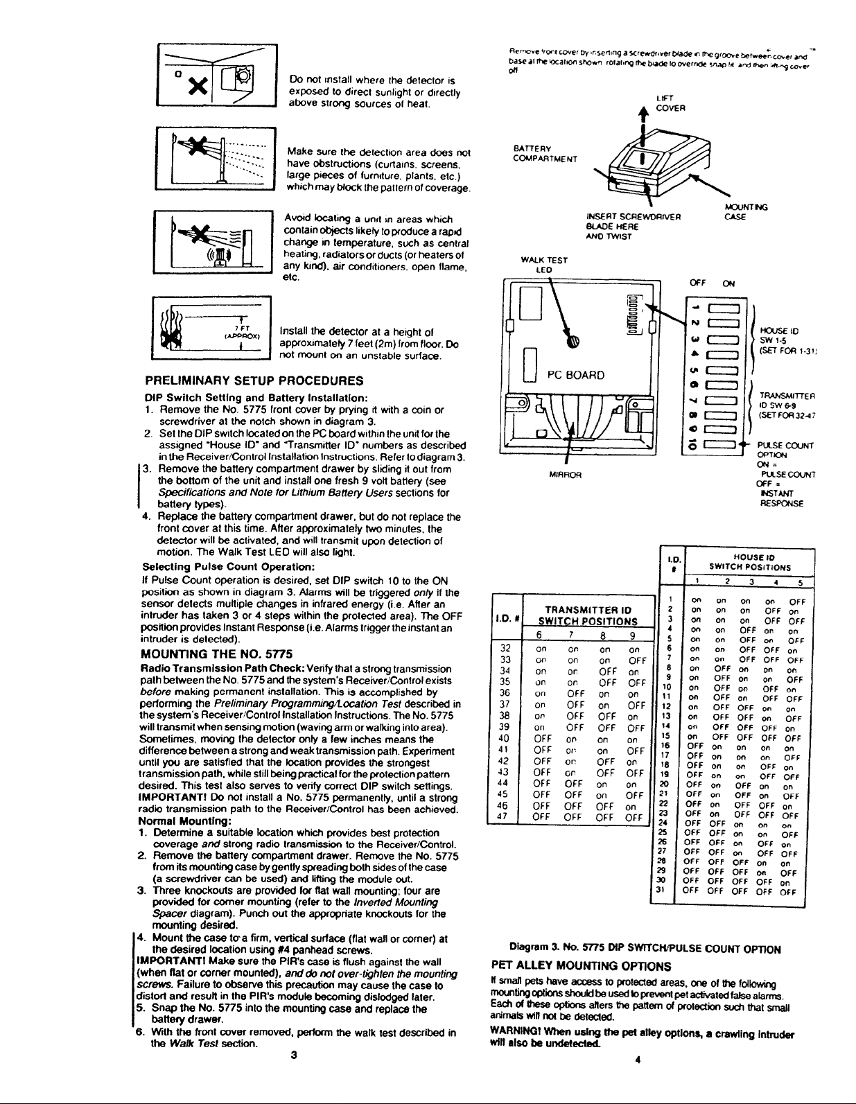
PRELIMINARY SETUP PROCEDURES
DIP Switch Setting and Battery Installation:
1
Remove the No. 5775 front rxwer by prying d with a coin or
screwdriver at the notch shown in d“iagram-3.
2.
Set the DIP switch located on the ~ board within the unit for the
assigned “House ID” and Transrmtfer ID- numbers as described
in the Receiver/Control Installation Instructions. Refer 10dtagram 3.
Remove the battery compartment drawer by slkting it out from
3.
the bottom of the unit and install one fresh 9 voii battery (see
Specifications and Note for Lithium flattery Users sections for
battery types).
4.
Replace the battery compartment drawer, but do not replace the
front cover at this ~me. After approximately two minufes, the
detector will be activated, and will transmit u~rr detection Of
motion. The Walk Test LED will also fiiht.
Selecting
If Pulse Count operation is desired, set DIP switch 10 to the ON
position as shown in diagram 3. Afarms will be triggered orrfy if the
sensor detects mutfiple changes in infrared energy (Le. After an
intruder has taken 3 or 4 steps within the prolecwd area). The OFF
positkrrr provides Instant Response (i.e. Alarms trigger the instant an
intruder is detected).
MOUNTING THE NO. 5775
Radio Transmission Path Check: Verify
palh between the No. 5775 and the system’s Receiver/Control exists
before making permanent inatallatiin. This is accomplished by
performing the Pre/imina~ r%gfammingbcdiorr Test described in
the system’s Receiver/Conlrol Installation Instructions. The No. 5775
will transmit when sensing motion (waving arm or walking intoarea).
Sometimes, moving the detector onfy a few inches means the
difference between a strong and weak transmission path. Experiment
until you are satisfied that the location provides the strongest
transmission path, while still being practical for the protection pattern
desired. This test also serves to verify correct DIP switch settings.
lMPORTANTf Do not install a No. 5775 permanently, until a strong
radio transmission
Normal Mounting:
1.
2. Remove the battery compartment drawer. Remove the No. 5775
from its mounting case by gently spreading both sides of the case
(a screwdriver can be used) and ring the mryjule wt.
3. Three knockouts are provided for flat wall mounting; four are
provided for corner mounting (refer to the hrveried Mounfirg
Spacer diagram). Punch out the appropriate knockouts for the
mounting desired.
4. Mount the case tcra firm, vertical surface (fiat wail or corner) at
the desired iocation using #4 parrhead screws.
IMPORTANT! Make sure the PiR’s case is flush againsf the wall
(when flat or comer mounted), and do not Lwt@ghferr fhe mounting
screws. Failure to C.@rve this precaution
distorf and result in the PIRs
5. Snap the No.
battery drawer.
6. With the front cover removed, perform the walk test described in
the Wdk Test section.
Pulse Count Operation:
thal a strong transmission
path to the Rea?iver/Control has been achieved.
Oetermine a suitable location which provides best protection
coverage and strong rad~ tranamissii to the Receiver/Control.
may cause the case 10
module becoming distodged later.
5775 into the mounting case and replace the
3
BATTERY
COMPARTMENT
WALK TEST
LEO
U PC BOARD
H
I
MIRROR
m
e
INSERT SCREWDIWVER CASE
SLAOE HERE
ANo TWIST
\
hcuNm4G
C+F c?4
II
HcwsE 10
SW 1.5
(S-H FCXi 1.31:
TRANSh4rTTE R
10 w 69
(SET FC+73247
PUSE CXXJNT
CPTION
m4=
PLSSECXXN7
OFF .
NSTIhl
RESPCt4SE
—
1.1
I
—
1
on on o“
2
i.D.
TRANSMITTER 10
SWITCH POSITIONS
6789
on on on
32
on on
33
on Ofi
34
on
35
on
36
on OFF on
37
OP
3a
on
39
40
OFF on on
41
OFF 0, 8F
42
OFF 0,
43
OFF OP
44
OFF
45
OFF OFF on 8F F
46
OFF OFF OFF on
47
OFF OFF
on OFF
OFF on
on
OFF OFF
OFF on on
OFF OFF on
OFF OFF OFF
YFF on
OFF OFF
OFF on
OFF OFF
On
OFF
F
on on On
3
on on on
4
on
0+7 on
:
on o“
7
on on
8
on
9
on
on
10
11
on
1?
on
13
on
14
on
Is
on
,6
OFF on on on on
17
OFF on on
18
OFF on
19
OFF on :
m
OFF on
21
OFF on
?2
OFF on
r?
OFF on
?4
OFF OFF on o“ ~“
?5
OFF OFF ~ on
6
OFF OFF on
17
OFF OFF on
s
OFF OFF OFF On on
9
3FF OFF OFF 011
OFF OFF OFF OFF on
>FF OFF OFF OFF OFF
u
Oiagram 3. No. ~5 OIP SWITCWPULSE COUNT OPTfON
PET ALLEY MOUNTING OPTiONS
ffsmaft pefshaveac03as
mourifingopfions SJM3ukfbeuaedtoprevent pet acfivatedfafsaatarms.
Each of these optii affera fhe pattern of protection SUL%that smafI
animals wifl not be detected.
WARNiNG!
When using the pat alley option% a crawting intruder
to protected areas, one of the fol~
Wfflalso be undetsdad.
4
HOUSE ID
SWITCH POSITIONS
1
?345
on
OFF on on
OFF w
OFF OFF or!
OFF OFF OFF
OFF On
OFF on ~
OFF on
OFF on OFF OFF
OFF OFF o.
OFF OFF on
OFF OFF OFF c,”
OFF OFF OFF OFF
OFF on
OFF on
OFF OFF on
OFF OFF OFF
&FF 00
OFF OFF
OFF on
O.
OFF on
OFF OFF
OFF on
OFF OFF
OFF
OFF
YFF
YFF
OFF
&FF
OFF
OFF
J
 Loading...