

ADEMCO 5707 Installation Instructions Manual
NS870 a%?
Previous Menu
5707
P!sEEEJ
WIRELESS TRANSMllTER
SMOKE DETECTOR
with BUILT-IN
INSTALLATION INSTRUCTIONS
GENERAL INFORMATION
The Ademco No. 57o7 Photoelectric Smoke Detector/Transmitter is intended for
use with wireless alarm systems that support 5700 series devices, and contains a
built-in transmitter which can send alarm, supervisory and battery condition
messages to the system’s receiverkontrol unit. Refer to the wireless system’s
instructions for the maximum number of transmitters that can be supported.
Alarm8
The smoke detector is powered by two 9-volt batteries and will sound its built-in
horn when smoke reaches the detector (the LED indicator will also light steadily).
A message will also be sent to the wireless control and the smoke detector’s ID
number will be displayed at the console. The alarm message will be transmitted
every 12 seconds, until the smoke condition has cleared and the detector has
reset. After the horn has stopped, a Restore message will be transmitted to the
control and it will then ba possible to clear the ID number from the display. During
normal or low battery conditions, the LED indicator will flash about once every 7
seconds,
Low Battery:
The detector indicates a low battery condition by emitting a “beep” about once
every 15 seconds. A low battery message will be sent to the control unit upon
any transmission following the first battery beep (with the detector’s ID number
displayed at the console). The battery should be replaced within 7 days following
the low battery signals.
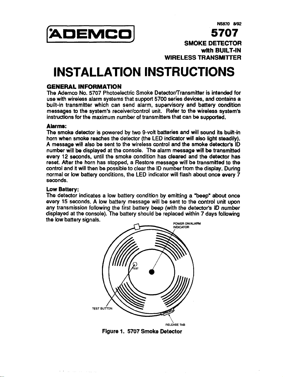
RM
TEST
REL& TAB
Figure 1. 5707 Smoke Detector
INSTALLATION PROCEDURE
Release the detector’s mounting bracket by pressing the tab marked PRESS in
the detector’s base (see Fig.1 for location of the tab). Note the manner in which
the bracket was attached to the detector base, then put the mounting bracket
aside temporarily. The mounting bracket also serves as the battery compartment
cover, but do not install the batteries yet..
Switch Settings
Dip
The detector’s DIP switches must be set for the assigned House ID and
Transmitter ID numbers before the unit will operate with the wireless system.
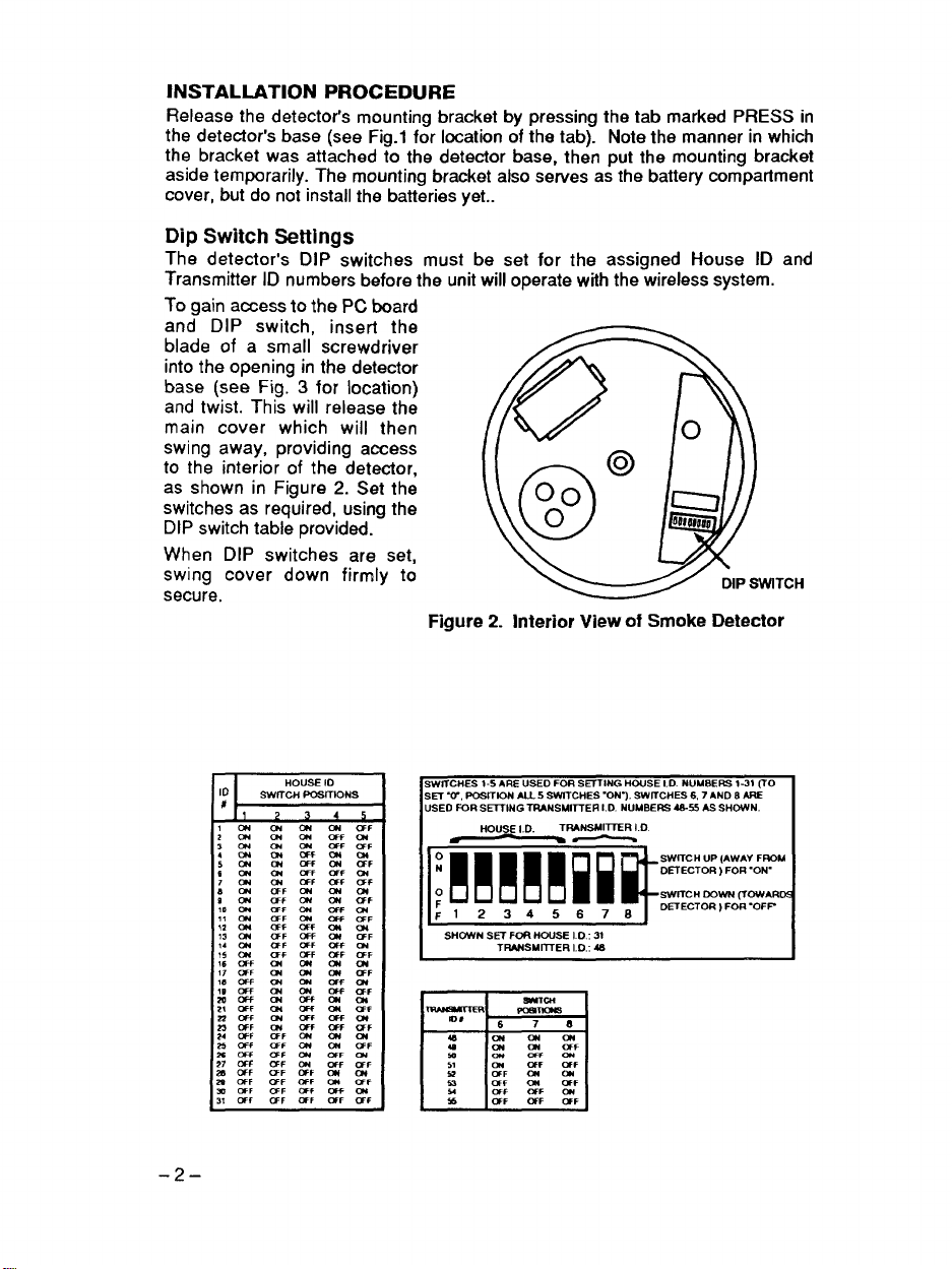
To gain access to the PC board
and DIP switch, insert the
blade of a small screwdriver
into the opening in the detector
base (see Fig. 3 for location)
and twist. This will release the
main cover which will then
swing away, providing access
to the interior of the detector,
as shown in Figure 2. Set the
switches as required, using the
DIP switch table provided.
When DIP switches are set,
swing cover down firmly to
secure.
Figure 2. Interior View of Smoke Detector
DIPSWITCH
-2–
SWITCHES 1-5 ARE USED FOR S~lNG HOUSE I.D. NUMBERS 1-31 (TO
SE7 ‘W, POSMON AILS SWITCHES .ON-). SWTCtiES 6.7 AND 8 ARE
USED FOR SE7TING TRANSMITTER I.D. NUMBERS 4S-55 AS SHOWN.
HOUSE I.D.
K!!!ml=:==m
SHCWN SET FoR HOUSE I D ,31
TRW4SMIT7ER I.D.: 4S
TRANSMITTER I.D
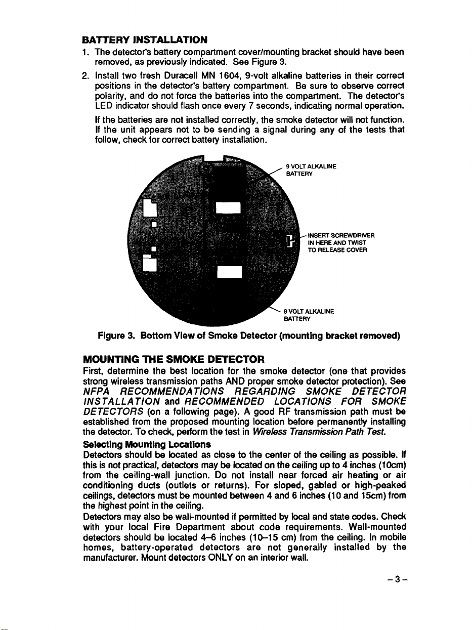
BAITERY INSTALLATION
1. The detectot% battery compartment cover/mounting bracket should have been
removed, as previously indicated. See Figure 3.
2. Install two fresh Duracell MN 1604, 9-volt alkaline batteries in their correct
positions in the detector’s battery compartment. Be sure to observe correct
polarity, and do not force the batteries into the compartment. The detector%
LED indicator should flash once every 7 seconds, indicating normal operation.
If the batteries are not installed correctly, the smoke detector will not function.
If the unit appears not to be sending a signal during any of the tests that
follow, check for correct battery installation.
INSERT S(
L
IN HERE AND TWIST
TO RELEASE COVER
-9 VOLT ALKALINE
‘VER
Figure 3. Bottom View of Smoke Detector (mounting bracket removed)
MOUNTING THE SMOKE DETECTOR
First, determine the best location for the smoke detector (one that provides
strong wireless transmission paths AND proper smoke detector protection). See
NFPA RECOMMENDATIONS REGARDING SMOKE DETECTOR
INS TALLA TION
DETECTORS
established from the proposed mounting location before permanently installing
the detector. To check, perform the test in
Sstsctlng Mounting
Detectors should be located as close to the center of the ceiling as possible. If
this is not practical, detectors maybe located on the ceiling up to 4 inches (1Ocm)
from the ceiling-wall junction. Do not install near forced air heating or air
conditioning ducts (outlets or returns). For sloped, gabled or high-peaked
ceilings, detectors must be mounted between 4 and 6 inches (1Oand 15cm) fmm
the highest point in the ceiling.
Detectors may also be wall-mounted if permitted by local and state codes. Check
with your local Fire Department about code requirements. Wall-mounted
detectors should be located 4-6 inches (1O-15 cm) from the ceiling. In mobile
homes, battery-operated detectors are not generally installed by the
manufacturer. Mount detectors ONLY on an inter”kx wall.
and RECOMMENDED LOCATIONS FOR SMOKE
(on a following page). A good RF transmission path must be
Wre/ess TramnissioII Path Test.
Locations
-3-
Wireless Transmission Path Test
A good RF transmission path must be established from the proposed mounting
location before permanently installing the smoke detector. To determine that
there is good signal reception from the proposed location, do the following:
1.
Activate the wireless system’s test mode.
2.
Depress and hold the smoke detector’s TEST button for at least 45 seconds.
Within 15 seconds, the detector’s horn will start to sound and the unit will
begin to transmit alarm signals about once every 12 seconds.
3.
The wireless system’s console will emit at least 3 tones each time an alarm
transmission is received, and will display the transmitting detector% ID
number.
4.
When the above has occurred, release the button. Within 10 seconds the
detector’s horn will stop. About 1 second later the ID number will clear from
the console display.
5.
If the console does not respond as noted, move the detector to another
location and repeat the transmission path test until a satisfactory location can
be found.
Detector Mountina Procedure
1
If the bracket is ir%talled on-the detector, remove the bracket by depressing
the release tab marked PRESS, then pivot the bracket away and free of the
detector.
2.
Use the bracket as a template to locate and mark two mounting holes. Drill
two 3/1 6 inch diameter holes, and insert the plastic expansion anchors. Hold
the bracket in place and thread the two screws (supplied) into the anchors.
Be careful to correctly orient the UP arrow on the bracket for correct
positioning of the detector if mounting on a wall. Tighten the screws.
3.
Install the detector (with batteries installed) onto the bracket as follows,
referring to Fgure 4
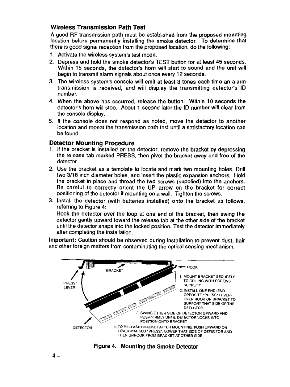
Hook the detector over the loop at one end of the bracket, then swing the
detector gently upward toward the release tab at the other side of the bracket
until the detector snaps into the locked position. Test the detector immediately
after completing the installation.
Important: Caution should be observed during installation to prevent dust, hair
and other foreign matters from contaminating the optical sensing mechanism.
-4–
“PRESS,’
LEVER
/
DETECTOR
BRACKET
(
PUSH FIRMLY UNTIL DETECTOR LOCKS INTO
4. TO RELEASE BRACKET AFTER MOUNTING, PUSH uPWARD ON
LEVER MARKED ,’PRESS”, LOWER THAT SIDE OF DETECTOR ANO
THEN UNHOOK FROM BRACKET AT OTHER SIDE.
Figure 4. Mounting the Smoke Detector
POSITION ONTO BRACKET.
❑RACKET SECURELY
1. MOUNT
TO CEILING WITH SCREWS
SUPPLIED.
2. INSTALL ONE ENO (END
OPPOSITE IIPRESS’, LEVER)
OVER HOOK ON BRACKET TO
SUPPORT THAT SIDE OF THE
DETEcTOR.
FDETEcTOR “PWARDAND
 Loading...