

ADEMCO 4275 Installation Instructions Manual
)c---- MARGIN LINES INDICATE PRINCIPAL CHANGES IN THIS ISSUE ‘-4
GENERAL INFORMATION
The AOEMCO No. 4275 Passii lntrared motiin detec-
within the area of detection: thus, when an intruder
tar/Remote Point Module is dasignad for use only with
crossas Or enters any tone. the resulting change in
tha VECTOR series sscurity systems. It is a versatile
intmrefl energy is detected and an alarm condition will
wall-mounted unit onering either wide-angle or long-
exist. Best coverage will be obtained if mounting is
range/curtain (narrow) area protection (2 separate
selected such that the likely direction of intruder
easy-to-install mirrors are supplied). The detector
motion is across the pattern.
senses sudden and slight changes in temperature
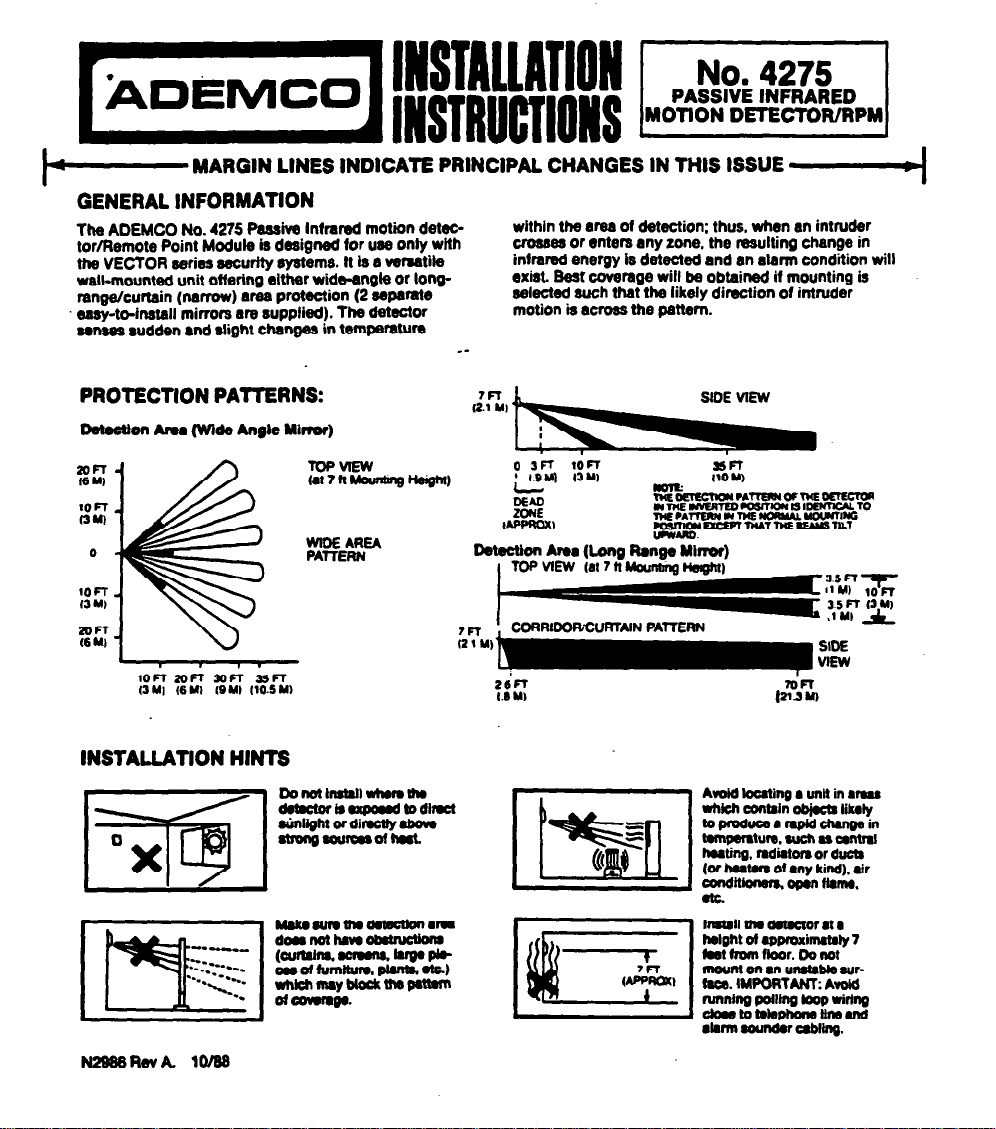
PROTECTION PATTERNS:
DetectIon Area (WI&4 Angle Ylrmf)
%
1OCr
ou)
0
4
-- ---.
r-m I LM
DetectIon Area (Long Ranga Minor)
1OcT
13
Ml
%z
M
rn
(2 1 U)
I
INSTALLATION HINTS
Donoth6t6llwhomuu
demctorrexpud~elrut
&Might or dimctty stmngwurw6ofhwt
AvoId
bating a unit in mu
whkh wntlin ob)ut8 lllly
s
toplwumrmpldch6ng6lll
tompersture. 8uch 66 oMtr6l
me
-5
(
hwthg. md*tom or ducb
loI h06Un
Of
my kii). elr
and- own nwn6.
!I
Wmtall the Wtutor 6l6
Mght ot
approximxtaty 7
kafrornf&or.Donot
wzx,
mouM
on l un6Ub& wrtwe. IMPoRTANT: Avole
anIn pollm0 moo wrhw
doatomkJotlomun6uKl
l lwln sounow UblbIg.
www.PDF-Zoo.com
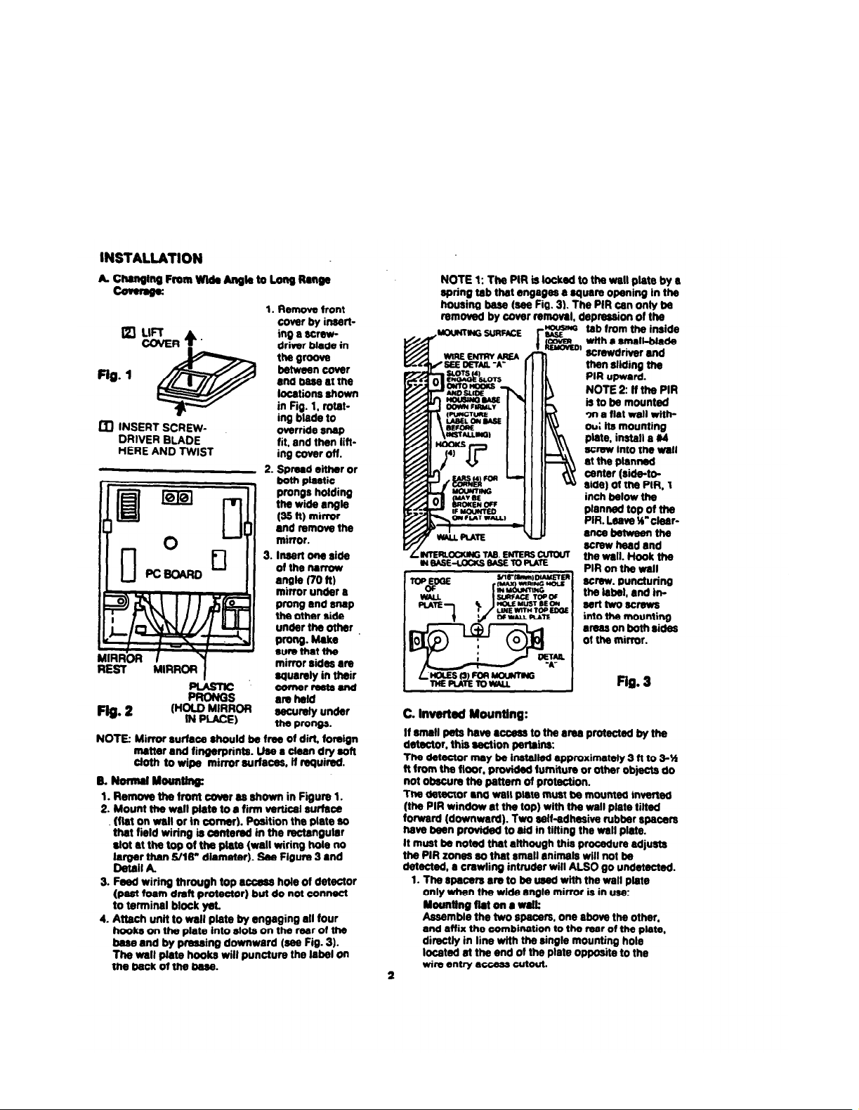
INSTALLATION
A CIUIQIIQ From Wtda Angb to Long Range
-
1. Remove front
Q! LIFT
COVER*.
Flg. 1
4i@
@3
m INSERT S&w-
DRIVER BLADE
HERE AND TWIST
cover by inserting a screwdriver blade in
ms groove
betweencover
and base at the
locatiins shown
in Fig. 1. rotating blade to
override snap
fit. and then lifting cover off.
2. Spread
either or
3.
both plastic
prongs holding
the wide angle
(35 tt) mirror
and remove the
mirror.
Insert one side
of the narrow
angle (70 ft)
mirror under a
prong and snap
the other side
under the other
Plong.Ue
sure mat tfte
mirror sides are
quarely in their
comerrastsand
am
ktld
securely under
the prongs.
NOTE: Mirror surface rhould be free of dirt, foretgn
matter and fingerprints. Use a clean dry soft
Cloth to wipe mirror surfaces. if required.
B. NomalYeuntln&
1.RemovethefrontcoverasshowninFigure1.
2. Mount the wall plate to a firm vertical surface
(Pat on wall or tn corner). Position the plate so
that field wirina is oentered in the rectanoular
slot at the top L the plate (wall wiring t&e no
laroer than S/16” diameter). See Flgure 3 and
De&l
A
3. Feed wiring through top access hole of
detector
(past
foam
dmfl protector)
but
do
not connect
to terminal block yet.
4. Attach unit to wall plate by engaging all four
hooks on the plate into slots on the rear of the
base and by pressing downward (sea Fig. 3).
The wall plate hooks will puncture the label on
me back of me base.
NOTE 1: The PIR is locked to the wall plate by a
spring tab that engages a quare opening In the
housing base (see Fig. 3). The PIR can only be
removed by cover removal.
depression of the
tab from the inside
wlth a small-blade
screwdriver and
pRn;;;i m
NOTE 2: If t-he PIR
is to ba mounted
3n a flat wall without its mounting
ptate. install a ff4
screw into the wall
at the planned
center (sidetoside) of the PIR. 1
inch below the
planned top of ths
PlR. Leave W’clearanca between the
screw head and
me wall.
Hook
the
PIR on the wall
screw, puncturing
the iabel, and Inserltwoscrews
into the mounting
areas on both sides
ot the mirror.
Fig. 2
.-.
C.
Invefted Mounting:
If small pets have
l
ccedm to the area protected by the
detector. thii 8ection pertains:
The detector may be installed approximately 3 ft to 3-H
ft from the floor, provided fumitum or other objects do
not obscure the pattern of protection.
The detector and wall plate must be mounted inverted
(the PIR window at the
top)
with the wall plate tilted
forward (downward). Two self-adhesii rubber spacers
have been provided to aid in tilting the wall plate.
It must be noted that although this procedure adjusts
the PIR zones so that small animals wfll not be
detected, a cmwling intruder will ALSO go undetected.
1. The spacers am to be used with the wall plate
only when the wide angle mirror is in use:
Wuntlngftatonawak
Assemble the two spacers, one abwe the other.
and affix the combination to the rear of the plate,
directly in line wfth the single mounting hole
located at the end of the plate opposite to the
wire entry access cutout.
2
.--..
www.PDF-Zoo.com
 Loading...