

ADEMCO 4192 Installation Instructions Manual
s:
MARGIN LINES INDICATE PRINCIPAL CHANGES IN THIS l/88 ISSUE *
GENERAL INFORMATION:
WIRING THE No. 4192
The ADEMCO No. 4192 PLUG-IN SMOKE DETECTOR BASE is a
VECTOR POINT PROTECTION SECURITY SYSTEM component. It IS
intended for use with interchangeable UL Ltsted detector heads, Model
BK-2851 B (PHOTOELECTRIC); Model BK-2851 BTH (PHOTOELECTRIC
WITH BUILT-IN THERMOSTAT) and Model BK-1851 B (IONIZATION). The
base can be installed on a standard ceiling mount electrical box and both
the base and the detector are powered through the polling loop.
IMPORTANT! The instructions which accompany the aforementtoned
detector heads only parttally pertatn to the No. 4192 SMOKE DETECTOR
BASE/TRANSPONDER. The relevant sections are: Preface; Specifica-
tions; SENSITIVITY TESTING AND MAINTENANCE, TAMPER-
PROOF FEATURE, and LIMITATIONS OF SMOKE DETECTORS.
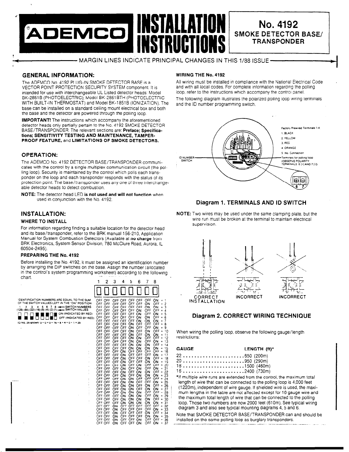
All wrring must be installed in compliance wrth the National Electrical Code
and with all local codes. For complete lnformatton regardrng the polltng
loop, refer to the instructions which accompany the control panel.
The followmg diagram illustrates the polarzed polling loop jwrrrng terminals
and the ID number programming switch.
OPERATION:
The ADEMCO No. 4192 DETECTOR BASE/TRANSPONDER communicates with the control by a stngle multiplex communrcation crrcutt (the pol-
ling loop). Security is maintained by the control which polls each transponder on the loop and each transponder responds wtth the status of Its
protection point. The base/transponder uses any one of three rnterchangeable detector heads to detect combustton.
NOTE: The detector head LED is not used and will not function when
used In contunction with the No. 4192.
INSTALLATION:
WHERE TO INSTALL
For information regarding findtng a suitable location for the detector head
and its base/transponder, refer to the BRK manual 156-210, Appltcatron
Manual for System Combustton Detectors (Available at no charge from
BRK Electrontcs, System Sensor Dtvisron, 780 McClure Road, Aurora, IL
60504-2495).
PREPARING THE No. 4192
Before installing the No. 4192. it must be assigned an identification number
by arranging the DIP switches on the base. Assign the number (allocated
in the control’s system programming worksheet) accordtng to the followtng
chart
.-
1 2345678
pm
OFF OFF OFF OFF
OFF OFF OFF OFF
OFF OFF OFF OFF
OFF OFF OFF OFF
OFF OFF OFF OFF
1) OFF OFF OFF OFF
OFF OFF OFF OFF
OFF OFF OFF OFF
OFF OFF. OFF OFF
OFF OFF OF: OFF
OFF OFF OFF OFF
OFF OFF OFF OFF
OFF OFF OFF OFF
OFF OFF OFF OFF
OFF OFF OFF OFF
OFF OFF OFF ON
OFF OFF OFF ON
OFF OFF
II
FF
OFF
OFF
OFF
OFF
OFF
“0:
:I
%
%
OFF
OFF
OFF
ON
ON
OFF
OFF
i%
i%
OFF
OFF
ml
OFF ON = 1
ON OFF = 2
ON ON = 3
OFF OFF = 4
OFF ON = 5
g; :‘N’:;
OFF OFF = 6
OFF ON = 9
ON OFF = 10
ON ON = 11
OFF OFF = 12
OFF ON = 13
ON OFF=14
ON ON = 15
OFF OFF = 16
OFF ON = 17
OFF = 16
ON = 1S
g’N’ : ;y
OFF = 22
:F”F : ;;
ON = 25
OFF OFF OFF ON ON OFF ON OFF = 26
OFF OFF OFF ON ON OFF ON ON = 27
OFF OFF OFF ON ON ON OFF OFF = 26
OFF OFF OFF ON ON ON OFF ON = 29
OFF OFF OFF ON ON ON ON OFF = 30
OFF OFF OFF ON ON ON ON ON = 31
OFF OFF ON OFF OFF OFF OFF OFF = 32
OFF OFF ON OFF OFF OFF OFF ON = 33
OFF OFF ON OFF OFF OFF ON OFF = 34
OFF OFF ON OFF OFF OFF ON ON = 35
OFF OFF ON OFF OFF ON OFF OFF = 36
OFF OFF ON OFF OFF ON OFF ON = 37
Diagram 1. TERMINALS AND ID SWITCH
NOTE: Two wires may be used under the same clamping plate. but the
wire run must be broken at the termtnal to matntarn electrical
supervision.
CORRECT
INCORRECT INCORRECT
INSTALLATION
Diagram 2. CORRECT WIRING TECHNIQUE
When wiring the polling loop, observe the following gauge/length
restrictions:
GAUGE LENGTH (ft)’
;i
. . . . . . . . . . . . . . . . . . . . . . 650 (200m)
. . . . . . . . . . . . . . . . . . . .950 (290m)
18 ::. . . . . . . . . . . . . . . . . . . .1500 (460m)
16 . . . . . . . . . . . . . . . . . . . . . .2400 (730m)
‘If multiple wire runs are extended from the control, the maximum total
length of wire that can be connected to the polling loop is 4,000 feet
(1220m). independent of wire gauge. If shrelded wtre is used, the maximum lengths in the table are not affected except for 16 gauge wire and
the maximum total length of wtre that can be connected to the polling
loop. Those two numbers are now 2000 feet (61 Om). See typical wiring
diagram 3 and also see typical mounting diagrams 4. 5 and 6.
Note that SMOKE DETECTOR BASE/TRANSPONDER can and should be
installed on the same polling loop as burglary transponders.
---.- ..___ -.-..-. ~_._.~
~..

-
.
VECTOR
CONTROL
--
4190 4196
0
c
,
Diagram 3. TYPICAL WIRING TO VECTOR SERIES C-COM
MOUNTING THE No. 4192
The ADEMCO No. 4192 SMOKE DETECTOR BASE!TRANSPONDER
mounts directly to 3-inch or 4-tnch octagon lunctron boxes, or with the
addition of a plaster ring or an ADEMCO specrally designed adapter plate,
to a 4-inch square lundron box
OCTAGON
BOX
Diagram 4:
TYPICAL MOUNTING DETAIL
_ --_
,.,‘..
.;------;
‘,\\
LEFToR
t’
i
DEECTOA
/
BASE
Diagram 5: DETAIL FOR MOUNT-
Diagram 6: DETAIL FOR MOUNTING DETECTOR BASE ON 4-INCH ING DETECTOR BASE ON A 4SQUARE JUNCTION BOX USING
PLASTER RING
INCH SQUARE JUNCTION BOX,
OR DIRECTLY TO CEILING,
USING ADEMCO ADAPTER
NOTE: Only two mounting screws are provided with each detector base.
The additional screws shown in Figure 5 and 6 for mounting the
plaster ring or the adapter bracket on the square junction box may
be supplied or purchased with the junction box.
TESTING THE lh%TALLATlON
Once all the detector bases have been wired and mounted, and the
wiring has been checked, the detector heads may be installed in the
loop
bases. To install the detector heads, line up the terminals in the base with
the holes in the bottom of the detector heads, insert the detector head, and
turn it about 10 degrees clockwise until the detent clicks into place.
NOTE: If a detector goes into alarm, it will reset only if all products of
combustion are cleared from the senstng chamber. If not. remove
the detector head from the base to cut off its power. Then reinstall
the detector head in the base.
TAMPER-PROOF FEATURE
These detector bases also include an optional tamper-proof tab that pre-
vents removal of the detector without the use of a tool. The tab is slipped
into a slot in the rim of the detector cover before the detector head is
installed in the detector base. Then the locking tab is pushed into the base
(See Frgures 7A and 78 on the next page). This prevents the detector head
from being turned counterclockwise and removed, unless the locking tab is
first released. To remove the detector head, insert a small-bladed screw
driver into release slot of tab and slide it out of the base. Then turn the
detector head counterclockwise about 10 degrees.
-__^--.. -..- -_.
CAUTION: TO AVOID POSSIBLE DAMAGE To clRculT, DISCON- NECT BOTH POLLING LOOP WIRES AT CONTROL PANEL PRIOR
TO INSTALLATION OR SERVICING THIS UNIT.
ALSO ONCE DETECTOR HEAD IS INSTALLED IN THE BASE, THE
OPTIONAL TAMPER-PROOF TAB MUST BE PUSHED INTO THE
BASE SO THAT WITHOUT TOOL, DETECTOR HEAD CANNOT BE
REMOVED FROM THE BASE. (SEE FIGURES 7A AND 78).
. -. _
 Loading...