

Adelpia TGL2010A-20 Service Manual
20″ LCD Color Monitor Adelpia TGL2010A
Service
Service
Service
Horizontal Frequency
31KHz-82KHz
TABLE OF CONTENTS
Description Page Description Page
Table Of Contents.......…….................……...........…........1
Important Safety Notice.………….…..................……......2
Revision List.…........................………................……......3
1.Monitor Specifications…...............................………........4
2.LCD Monitor Description…………………………….......5
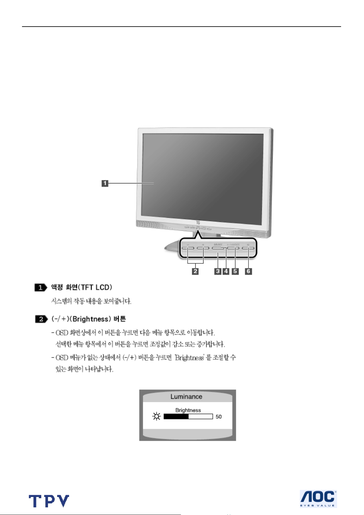
3.Operation Instruction…………...............……...........6
3.1 General Instructions.......................................…...........6
3.2 Control Buttons………..…….…..............……...............6
3.3 Adjusting the Picture...........................…............8
4.Input/Output Specification............……………............10
4.1 Input Signal Connector......….…..……........…….........10
4.2 Factory Preset Display Modes........…...............11
4.3 Power Supply Requirement…………………………....12
4.4 Panel Specification..............………………..................13
5.Block Diagram…….…...................…………................15
5.1 Software Flow Chart…………………….……....….......15
5.2 Electrical Block Diagram…………..……..…..….......17
6.Schematic……………...............................….....19
6.1 Main Board..............................................................19
6.2 Power Board....…………..........……........................24
6.3 Audio Board....…………….......……........................26
7.PCB Layout..…………...........……...........................27
7.1 Main Board………..................……....................27
7.2 Power Board…....................……………..................30
7.3 Key Board……….....…….............……….................32
8.Maintainability………............................……….........33
8.1 Equipments and Tools Requirement......……….......33
8.2 Trouble Shooting………………................................33
9.White-Balance, Luminance adjustment.............39
10. Monitor Exploded View……...………………............40
11.BOM List…................……......................….............41
12. Different Parts List…………………………………….56
SAFETY NOTICE
ANY PERSON ATTEMPTING TO SERVICE THIS CHASSIS MUST FAMILIARIZE HIMSELF WITH THE CHASSIS
AND BE AWARE OF THE NECESSARY SAFETY PRECAUTIONS TO BE USED WHEN SERVICING ELECTRONIC
EQUIPMENT CONTAINING HIGH VOLTAGES.
CAUTION: USE A SEPARATE ISOLATION TRANSFOMER FOR THIS UNIT WHEN SERVICING
1

20″ LCD Color Monitor Adelpia TGL2010A
Important Safety Notice
Proper service and repair is important to the safe, reliable operation of all AOC Company Equipment. The service
procedures recommended by AOC and described in this service manual are effective methods of performing service
operations. Some of these service operations require the use of tools specially designed for the purpose. The special
tools should be used when and as recommended.
It is important to note that this manual contains various CAUTIONS and NOTICES which should be carefully read in
order to minimize the risk of personal injury to service personnel. The possibility exists that improper service methods
may damage the equipment. It is also important to understand that these CAUTIONS and NOTICES ARE NOT
EXHAUSTIVE. AOC could not possibly know, evaluate and advise the service trade of all conceivable ways in which
service might be done or of the possible hazardous consequences of each way. Consequently, AOC has not
undertaken any such broad evaluation. Accordingly, a servicer who uses a service procedure or tool which is not
recommended by AOC must first satisfy himself thoroughly that neither his safety nor the safe operation of the
equipment will be jeopardized by the service method selected.
Hereafter throughout this manual, AOC Company will be referred to as AOC.
WARNING
Use of substitute replacement parts, which do not have the same, specified safety characteristics might create shock,
fire, or other hazards.
Under no circumstances should the original design be modified or altered without written permission from AOC. AOC
assumes no liability, express or implied, arising out of any unauthorized modification of design.
Servicer assumes all liability.
FOR PRODUCTS CONTAINING LASER:
DANGER-Invisible laser radiation when open AVOID DIRECT EXPOSURE TO BEAM.
CAUTION-Use of controls or adjustments or performance of procedures other than those specified herein may result
in hazardous radiation exposure.
CAUTION -The use of optical instruments with this product will increase eye hazard.
TO ENSURE THE CONTINUED RELIABILITY OF THIS PRODUCT, USE ONLY ORIGINAL MANUFACTURER'S
REPLACEMENT PARTS, WHICH ARE LISTED WITH THEIR PART NUMBERS IN THE PARTS LIST SECTION OF
THIS SERVICE MANUAL.
Take care during handling the LCD module with backlight unit
-Must mount the module using mounting holes arranged in four corners.
-Do not press on the panel, edge of the frame strongly or electric shock as this will result in damage to the screen.
-Do not scratch or press on the panel with any sharp objects, such as pencil or pen as this may result in damage to the
panel.
-Protect the module from the ESD as it may damage the electronic circuit (C-MOS).
-Make certain that treatment person’s body is grounded through wristband.
-Do not leave the module in high temperature and in areas of high humidity for a long time.
-Avoid contact with water as it may a short circuit within the module.
-If the surface of panel becomes dirty, please wipe it off with a soft material. (Cleaning with a dirty or rough cloth may
damage the panel.)
2
20″ LCD Color Monitor Adelpia TGL2010A
Revision List
Version Date Revision History TPV Model Name
A00 Oct-16-06 Initial Release TA6GM1DFW1UGNP
A01 Mar.-27-07 Add TPV Model in item 12 TA6CM1DFW1UGNP
A02 May.-14-07 Add TPV Model In Item 12 TA6GM1DFW1UGNC
3
20″ LCD Color Monitor Adelpia TGL2010A
1. Monitor Specifications
Items Description
Driving system TFT Color LCD
Panel Type LM201WE3
Size 51.1cm (20.1")
Pixel pitch 0.258mm (H) x 0.258mm (V)
LCD Panel
Input
Power Consumption
Viewable angle
Response time (type) 5 ms
Display Color 16.7M
Contrast Ratio 800:1
White Luminance 300cd/m
Sync. Type H/V TTL
Input Connector
Input Video Signal Analog, Digital
H-Frequency 31kHz – 82kHz
V-Frequency 56-75Hz
ON Mode ≤49W
OFF Mode
160(H) 160(V)
2
D-Sub 15pin,DVI 24pin
≤1W
Max Dot Clock 146.25MHz
Max. Resolution 1680 x 1050
Plug & Play VESA DDC2BTM
Power Source 100~240VAC,47~63Hz
Maximum Screen Size
Dimensions 398.5 mm (H) x472.3 mm (W) x182 mm (D)(NO Packed)
Weight Monitor only: 5.5 kg
Environmental
Considerations
Horizontal : 459.4mm
Vertical: 296.4mm
Operating Temp: 5°C to 35°C
Storage Temp: -20°C to 60°C
Operating Humidity: 10% to 85%
4
20″ LCD Color Monitor Adelpia TGL2010A
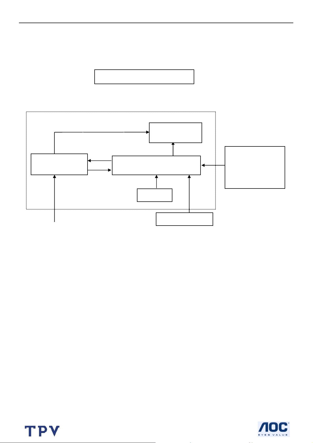
2. LCD Monitor Description
The LCD monitor will contain a main board, a power board, and a key board which house the flat panel control logic,
brightness control logic and DDC.
The Inverter board will drive the backlight of panel and DC-DC conversion.
Power Board
AC-IN
100V-240V
CCFL Drive.
Monitor Block Diagram
Flat Panel and
CCFL Backlight
Main Board
Key board
HOST Computer
RS232 Connector
For white balance
adjustment in factory
mode
Video signal, DDC
5
20″ LCD Color Monitor Adelpia TGL2010A
3. Operating Instructions
3.1 General Instructions
Press the power button to turn the monitor on or off. The other control buttons are located at front panel of the
monitor. By changing these settings, the picture can be adjusted to your personal preferences.
• The power cord should be connected.
• Connect the video cable from the monitor to the video card.
• Press the power button to turn on the monitor position. The power indicator will light up.
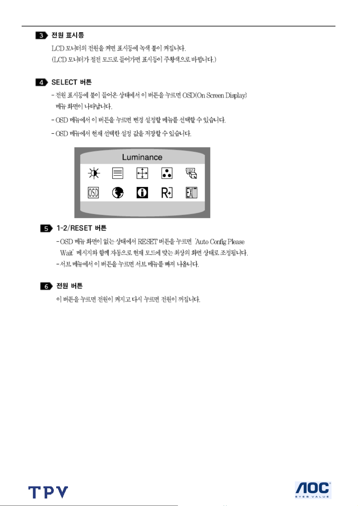
3.2 Control Buttons
6
20″ LCD Color Monitor Adelpia TGL2010A
7
20″ LCD Color Monitor Adelpia TGL2010A
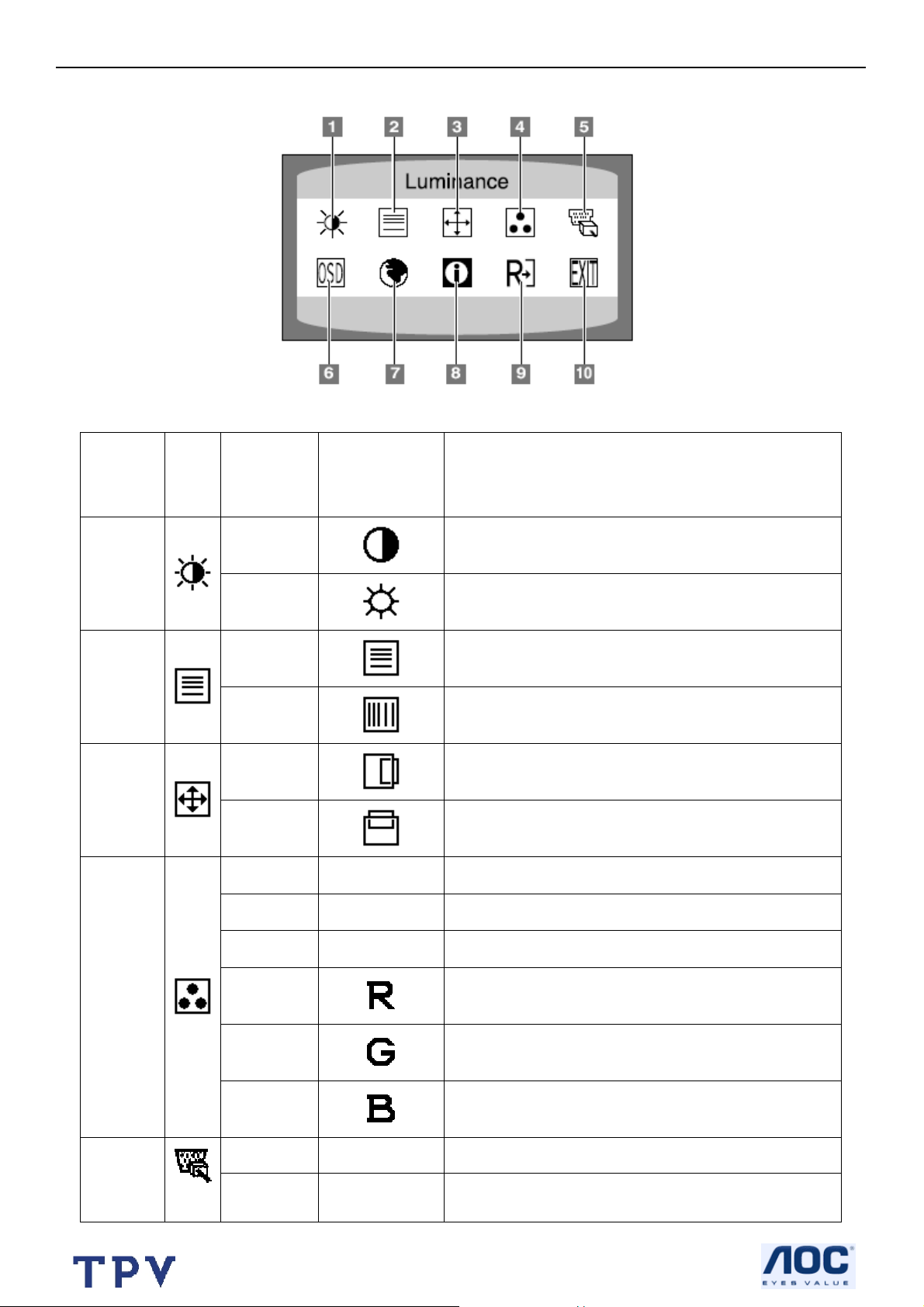
3.3 Adjusting the Picture
THE DESCRIPTION FOR CONTROL FUNCTION:
Main Menu
Item
Luminance
Image
Setup
Image
Position
Main
Menu
Icon
Sub Menu
Item
Contrast
Brightness
Focus
Clock
H. Position
V. Position
Warm N/A Recall Warm Color Temperature from EEPROM.
Sub Menu Icon Description
Contrast from Digital-register.
Backlight Adjustment
Adjust Picture Phase to reduce Horizontal-Line noise
Adjust picture Clock to reduce Vertical-Line noise.
Adjust the horizontal position of the picture.
Adjust the vertical position of the picture.
Cool N/A Recall Cool Color Temperature from EEPROM.
sRGB N/A Recall sRGB Temperature from EEPROM.
Color
Te mp .
Input
Select
User / Red
User / Green
User / Blue
Analog
Digital N/A Select input signal from digital source (DVI)
N/A Select input signal from analog source (D-Sub)
8
Red Gain from Digital-register.
Green Gain Digital-register.
Blue Gain from Digital-register.
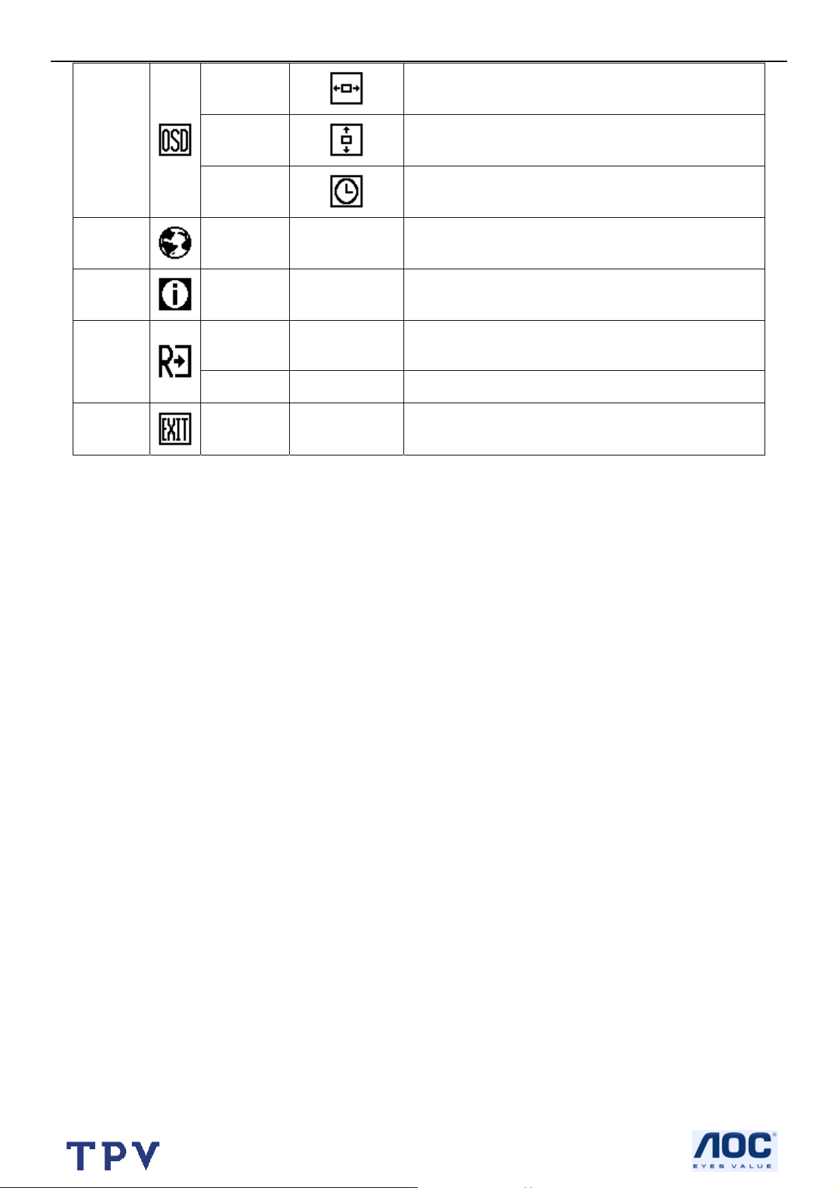
20″ LCD Color Monitor Adelpia TGL2010A
OSD Setup
Language
Information
Reset
Exit
H. Position
V. Position
OSD Timeout
Language N/A Select the language you like.
Information N/A
Yes N/A Clear each old status of Auto-configuration.
No N/A Do not execute reset, return to main menu.
N/A N/A Exit OSD
Adjust the horizontal position of the OSD.
Adjust the vertical position of the OSD.
Adjust the OSD timeout.
Show the resolution, H/V frequency and input port of
current input timing.
9
20″ LCD Color Monitor Adelpia TGL2010A
4. Input/Output Specification
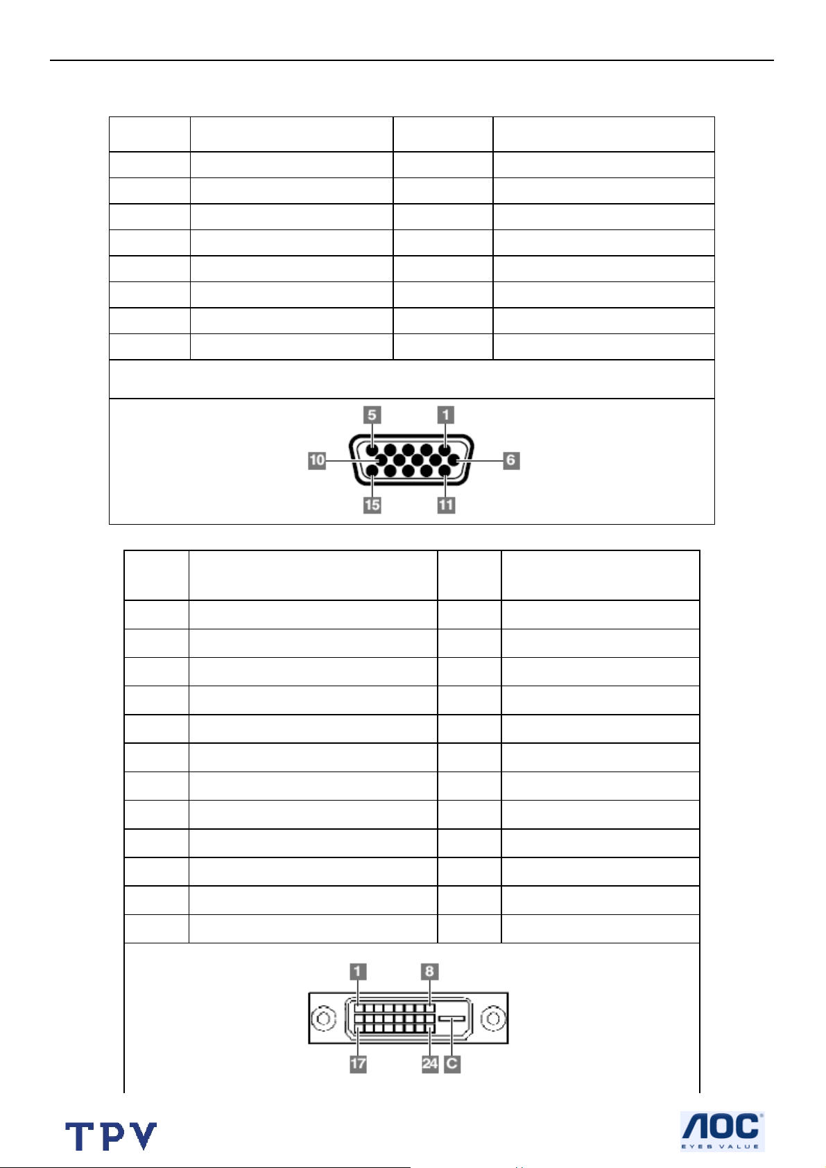
4.1 Input Signal Connector
Pin No. Description Pin No. Description
1. Red 9. +5V
2. Green 10. Logic Ground
3. Blue 11. NC
4. NC 12. DDC-Serial Data
5. DDC-Return 13. H-Sync
6. R-Ground 14. V-Sync
7. G-Ground 15. DDC-Serial Clock
8. B-Ground
VGA connector
Pin No.
1.
2.
3.
4.
5.
TMDS Data 2-
TMDS Data 2+
TMDS Data 2/4 Shield
TMDS Data 4-
TMDS Data 4+
Description Pin No. Description
13.
14.
15.
16.
17.
TMDS Data 3+
+5V Power
Ground(for+5V)
Hot Plug Detect
TMDS Data 0-
6.
7.
8.
9.
10.
11.
12.
DDC Clock
DDC Data
Analog Vertical Sync
TMDS Data 1-
TMDS Data 1+
TMDS Data 1/3 Shield
TMDS Data 3-
10
18.
19.
20.
21.
22.
23.
24.
TMDS Data 0+
TMDS Data 0/5 Shield
TMDS Data 5-
TMDS Data 5+
TMDS Clock Shield
TMDS Clock +
TMDS Clock -
20″ LCD Color Monitor Adelpia TGL2010A
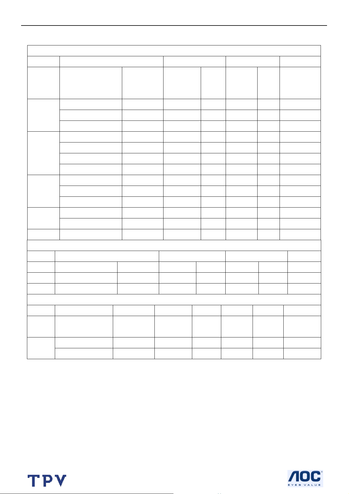
4.2 Factory Preset Display Modes
VESA MODES
Horizontal Vertical
Nominal
Mode Resolution Total
640x480@60Hz 800 x 525 31.469 N 59.940 N 25.175
VGA
SVGA
XGA
SXGA
WSXGA 1680x1050@60Hz 2240x1089 65.29 N 59.95 P 146.25
640x480@72Hz 832 x 520 37.861 N 72.809 N 31.500
640x480@75Hz 840 x 500 37.500 N 75.00 N 31.500
800x600@56Hz 1024 x 625 35.156 N/P 56.250 N/P 36.000
800x600@60Hz 1056 x 628 37.879 P 60.317 P 40.000
800x600@72Hz 1040 x 666 48.077 P 72.188 P 50.000
800x600@75Hz 1056x625 46.875 P 75.000 P 49.500
1024x768@60Hz 1344x806 48.363 N 60.004 N 65.000
1024x768@70Hz 1328x806 56.476 N 70.069 N 75.000
1024x768@75Hz 1312x800 60.023 P 75.029 P 78.750
1280x1024@60Hz 1688x1066 63.981 P 60.020 P 108.000
1280x1024@75Hz 1688x1066 79.976 P 75.025 P 135.000
Frequency
+/- 0.5kHz
Sync
Polarit
y
Nominal
Freq.
+/- 1 Hz
Sync
Polari
ty
Nominal
Pixel Clock
(MHz)
IBM MODES
Horizontal Vertical
DOS 720x400@70Hz 900 x 449 31.469 N 70.087 P 28.322
DOS 640x350@70Hz 800 x 449 31.469 P 70.087 N 25.175
XGA 1024x768@72Hz 1304 x 798 57.515 P 72.1 P 75.000
MAC MODES
VGA 640x480@67Hz 864x525 35.000 N 66.667 N 30.240
SVGA
832x624@75Hz 1152x667 49.725 N 74.551 N 57.2832
1024x768@60Hz 1312x813 48.780 N 60.001 N 64.000 XGA
1024x768@75Hz 1328x804 60.241 N 74.927 N 80.000
11
20″ LCD Color Monitor Adelpia TGL2010A
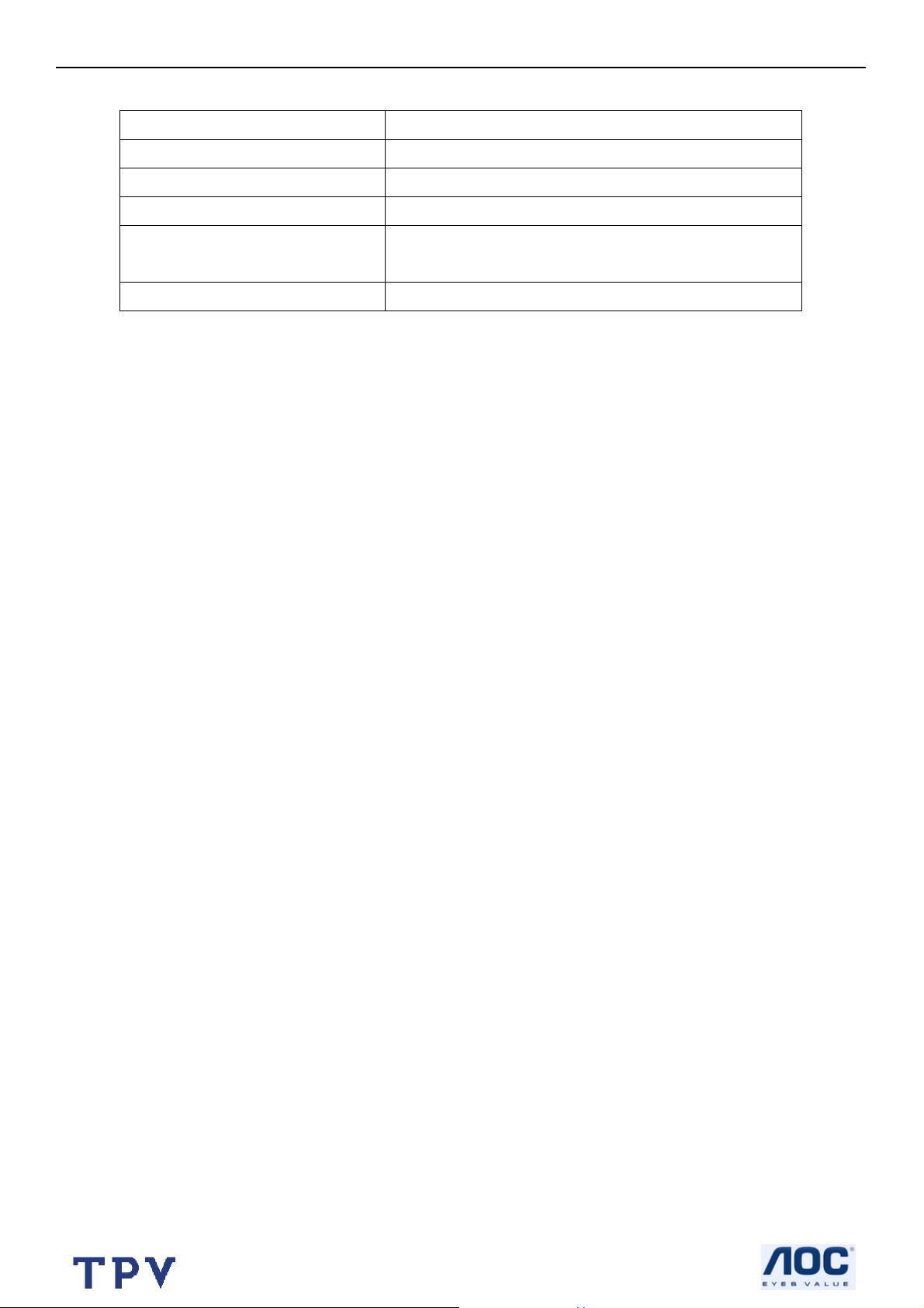
4.3 Power Supply Requirement
A/C Line voltage range 100 V ~ 240 V
A/C Line frequency range
Peak surge current < 55A peak at 240 VAC and cold starting
Leakage current < 3.5mA
Power line surge
DC output Voltage
50 ± 3Hz, 60 ± 3Hz
No advance effects (no loss of information or defect)
with a maximum of 1 half-wave missing per second
12VDC± 5%
12
20″ LCD Color Monitor Adelpia TGL2010A
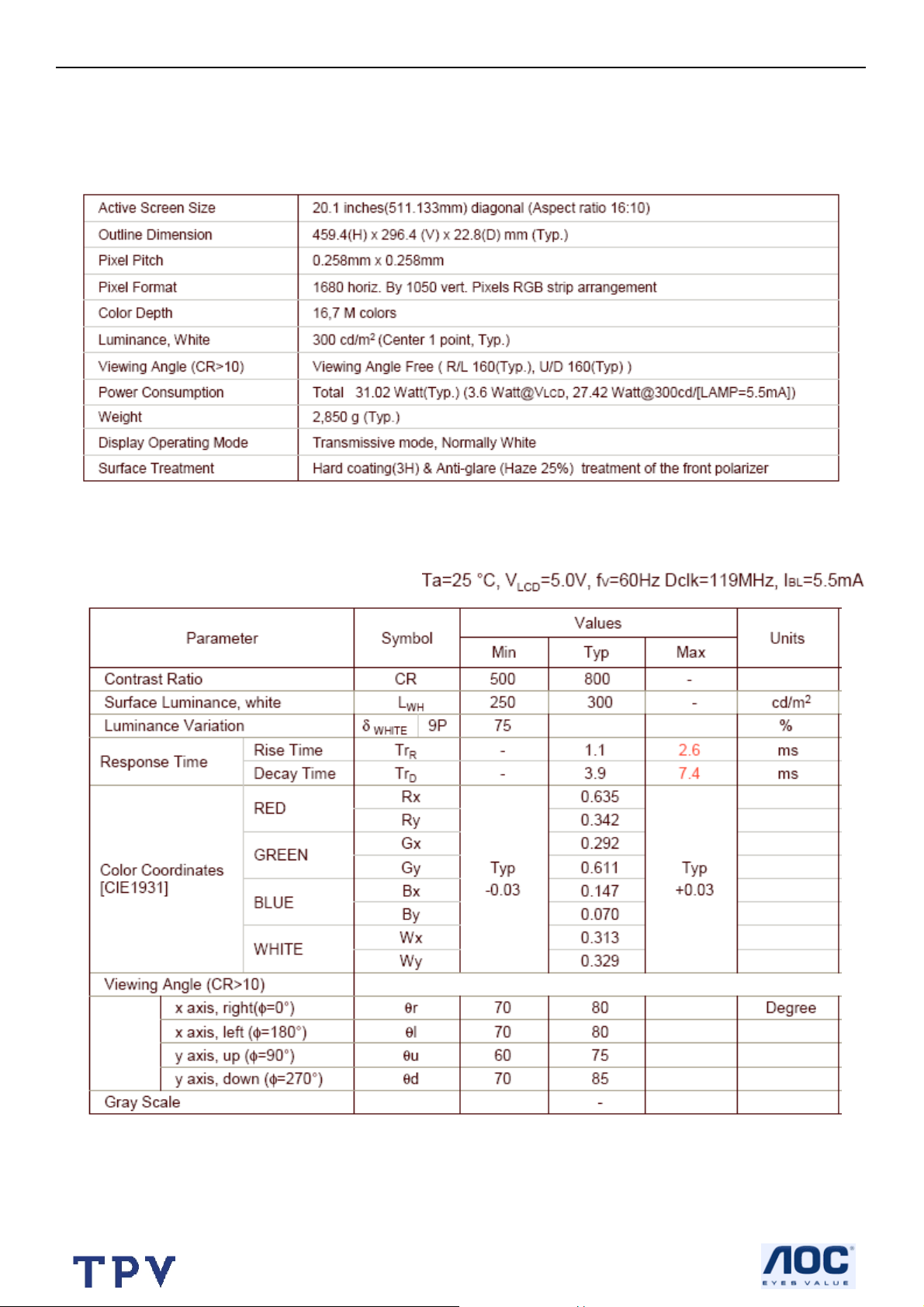
4.4 Panel Specification
LM201WE3
4.4.1 General Features
4.4.2 Optical Characteristics
13
20″ LCD Color Monitor Adelpia TGL2010A
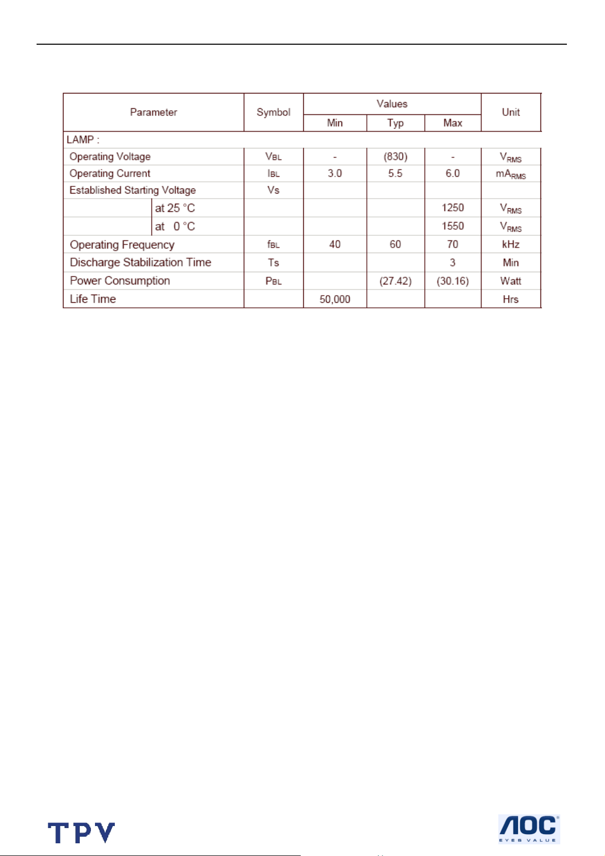
4.4.3 Electrical Characteristics
14
20″ LCD Color Monitor Adelpia TGL2010A
5. Block Diagram
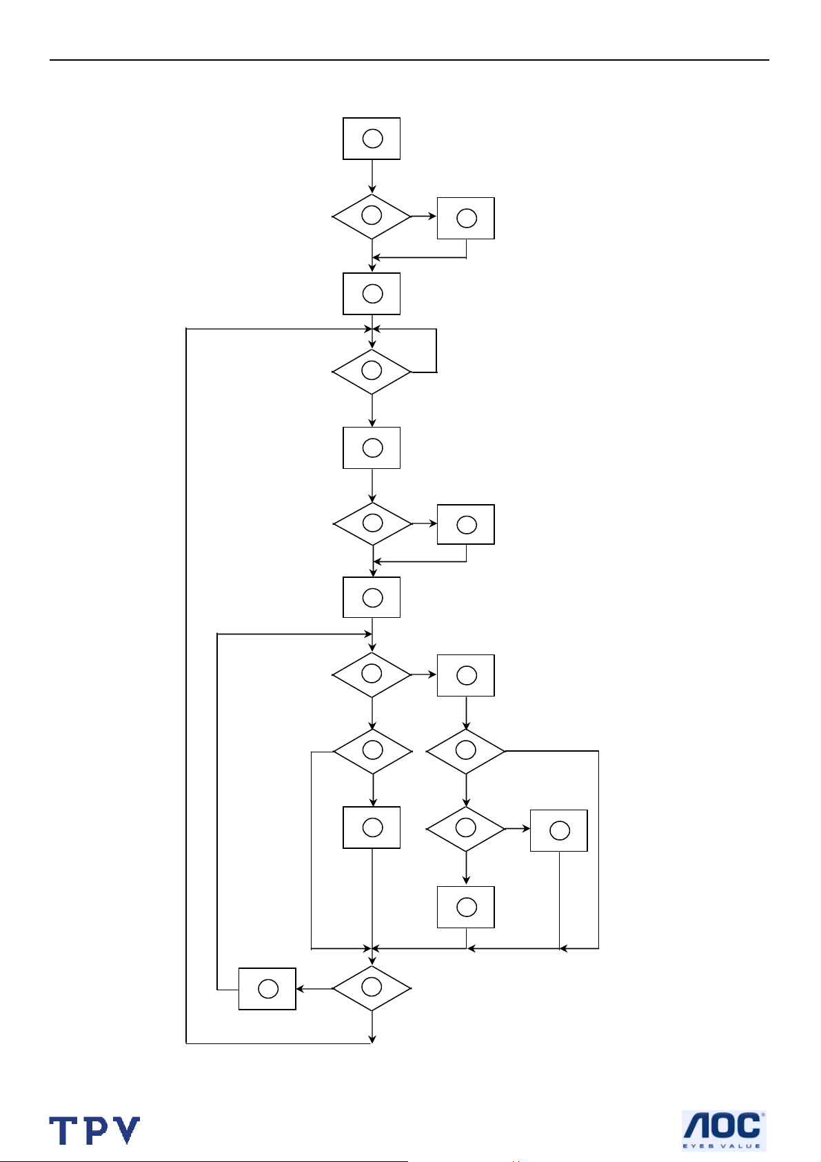
5.1 Software Flowing Chart
1
2
4
Y
3
N
N
10
12
5
Y
6
7
9
Y
N
N
Y
N
8
11
13
N
Y
14
18
N
19
Y
15
15
17
Y
N
16
Y
20″ LCD Color Monitor Adelpia TGL2010A
REMARK:
1) MCU initializes.
2) Is the EPROM blank?
3) Program the EPROM by default values.
4) Get the PWM value of brightness from EPROM.
5) Is the power key pressed?
6) Clear all global flags.
7) Are the AUTO and SELECT keys pressed?
8) Enter factory mode.
9) Save the power key status into EPROM.
Turn on the LED and set it to green color.
Scalar initializes.
10) In standby mode?
11) Update the lifetime of back light.
12) Check the analog port, are they’re any signals coming?
13) Does the scalar send out an interrupt request?
14) Wake up the scalar.
15) Are there any signals coming from analog port?
16) Display "No connection Check Signal Cable" message. And go into standby mode after the message
disappears.
17) Program the scalar to be able to show the coming mode.
18) Process the OSD display.
19) Read the keyboard. Is the power key pressed?
16
20″ LCD Color Monitor Adelpia TGL2010A
(
)
5.2 Electrical Block Diagram
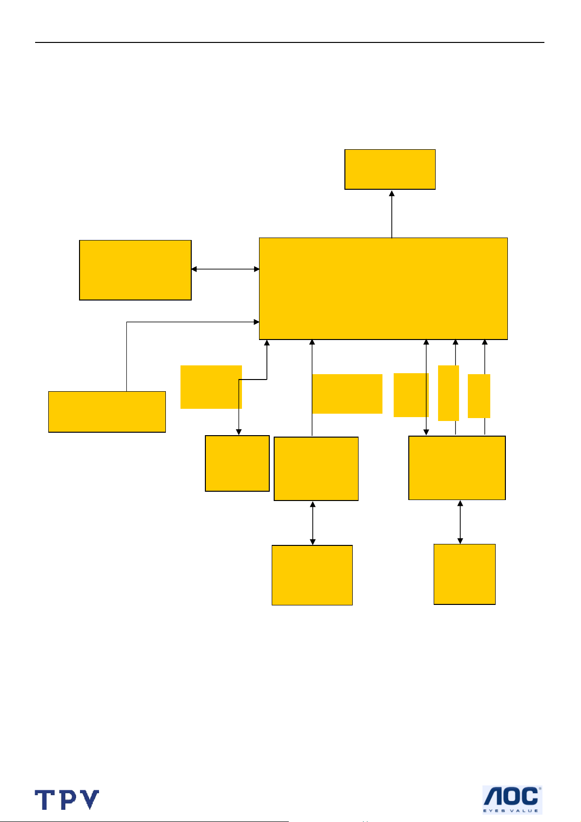
5.2.1 Main Board
Flash Memory
PM25LV010-25 SCE
(U402)
(Include MCU, ADC, OSD)
LCD Interface
(CN101)
Scalar TSUMU58J
(U401)
OSD Control Interface
(CN403)
EPR_SDA
EPR_SCL
EEPROM
24LC16B
U403
Connector
(CN406)
EEPROM
M24C02
(U405)
Digital video
signal
DVI
DDC_SCL_DVI,
DDC_SDA_DVI
RXD
TXD
R
H
G
V
B
D-Sub
Connector
(CN405)
DB15_SDA
DB15_SCL
EEPROM
M24C02
(U404)
17
20″ LCD Color Monitor Adelpia TGL2010A
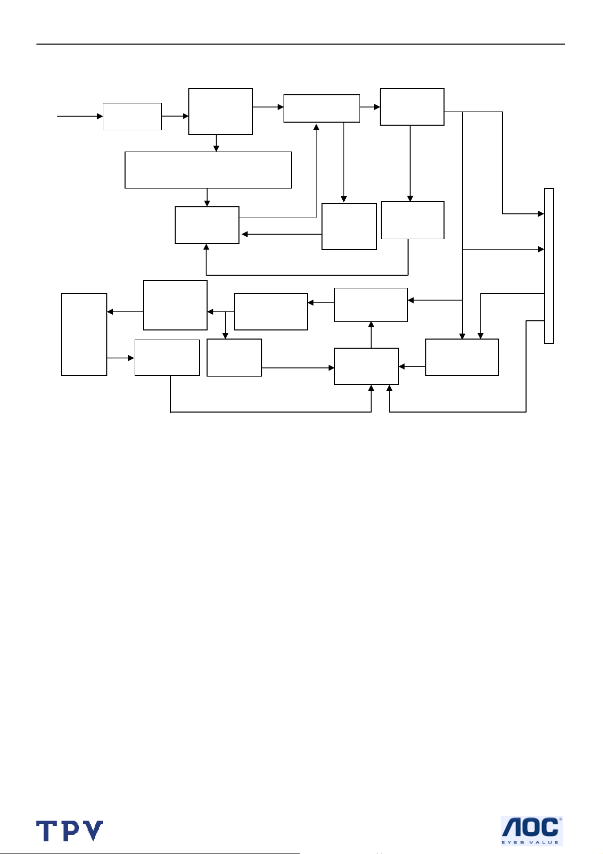
5.2.2 Power Board
AC input
EMI filter
Start Circuit: R904、R932、R933
Bridge
Rectifier
and Filter
Transformer
Rectifier
diodes
Lamp
Output
Circuit
Feedback
Circuit
PWM
Control IC
Over
Voltage
Transformer
Over
Voltage
Protect
MOSFET
PWM
Control IC
Feedback
Circuit
ON/OFF
Control
DIM
DIM
5V
12V
ON/OFF
18
 Loading...