

Page 1
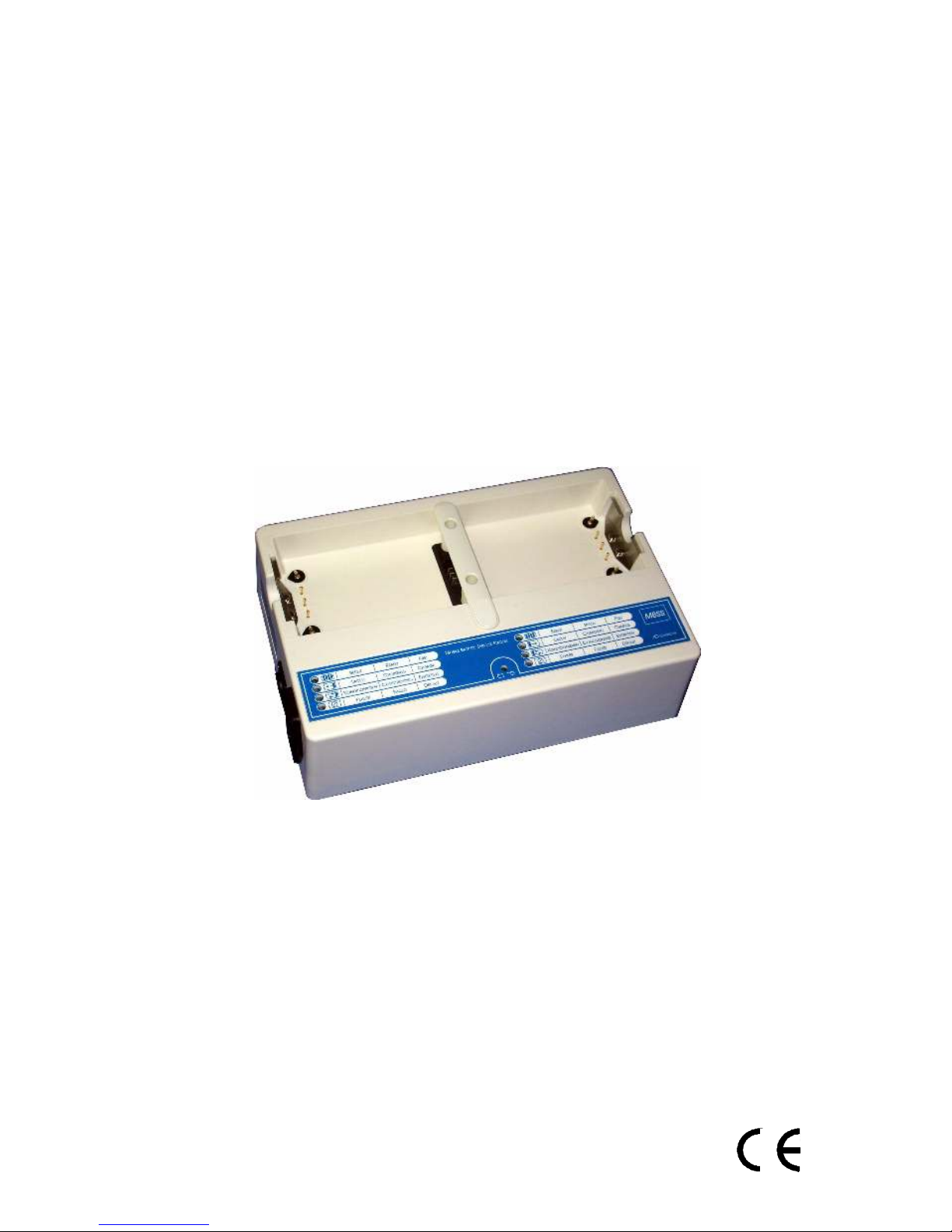
User Manual
MBSS
MOBILE BATTERIE SERVICE STATION
Before using the device,
please read this user manual
V1.4
gb –Subject to technical changes without notification.
Page 2

Page 2 User Manual "MBSS"
Table of Contents
1. Intended use....................................................................................3
2. Versions ..........................................................................................3
3. Items included.................................................................................3
4. Important safety instructions...........................................................4
5. Charging Algorithm ........................................................................5
6. Power supply...................................................................................6
7. Controls...........................................................................................7
8. Displays ..........................................................................................7
9. Symbols ..........................................................................................8
10. Initial Operation..............................................................................8
11. Charging the batteries .....................................................................9
12. Conditioning the batteries .............................................................10
13. Errors ............................................................................................11
14. Troubleshooting............................................................................12
15. Cleaning and disinfection..............................................................13
16. Maintenance and Safety Test ........................................................13
17. Packaging......................................................................................13
18. Disposal ........................................................................................13
19. Installation and use of wall mount for MBSS ...............................14
20. Specifications................................................................................15
21. EC Declaration of Conformity......................................................16
Page 3

User Manual "MBSS" Page 3
1. Intended use
The "MBSS" charging station can be used to charge NiCd or SLA batteries of the
Fastpak®, Fastpak 2®and Lifepak®series manufactured by Medtronic-Physio Control.
Do not attempt to insert batteries of any other type or manufacturer.
Warning !
During stand-by and operation defibrillators must be equipped with fully charged
batteries. During stand-by and operation of the defibrillator, the "MBSS" must be
used for charging extra battery packs only.
2. Versions
The "MBSS" charging station is available as a table top or wall mount device. For
installation in emergency vehicles, use the wall mount device and the supplied
original wall mount only.
Please contact our customer service in case a device is to be modified from table top
to wall mount or vice versa.
• Table top device
The "MBSS" table top device is equipped with non-skidding rubber elements.
• Wall mount device
The "MBSS" wall mount device is equipped with metal studs for installation with
a special wall mount which is supplied with the device. If installed correctly, this
wall mount is approved for mobile use in emergency vehicles.
3. Items included
1 "MBSS" battery charger as table top or wall-mount version
1 Power cord
1 User manual including declaration of conformity
In addition, wall mount devices include the following items:
1 Connection cable for 12 V operation
1 Wall mount
1 Instructions for wall mount installation
Page 4

Page 4 User Manual "MBSS"
4. Important safety instructions
Before using the "MBSS" device for the first time, please read the following safety
instructions carefully. The manufacturer, AD Elektronik GmbH, shall not be responsible
and / or liable for any failure or damage originating from improper or negligent
handling.
• Do not cover, tape or alter the cooling fins in any way. The device must be
installed or placed in a way that sufficient air circulation for proper cooling is
ensured.
• For installation in emergency vehicles use wall mount devices with, original wall
mount only.
• To connect the device with the mains, supply use, the included original cable
only.
• Install the power cord in a safe and secure way. Do not use damaged or faulty
cables under any circumstances.
• In case of a malfunction, disconnect the power supply and contact you customer
service representative. The device must be repaired by authorised personal only.
All responsibility and liability of the manufacturer AD Elektronik GmbH will
become void as soon as the device housing is opened by an unauthorised person.
• Install the device so that the LED display is visible. Minimise exposure to direct
sunlight.
• For continuous reference, always keep the operating instructions close to the
device.
Page 5

User Manual "MBSS" Page 5
5. Charging Algorithm
• NiCd batteries
The "MBSS" uses a special pulse charging algorithm which is monitored by a
microcontroller. The battery is charged using high current and it is discharged
periodically with an even higher current. The MBSS battery charger converts
more energy into charging current than conventional constant current chargers and
avoid the so-called memory effect to a large extent. With this pulsed charging
cycle, your NiCd battery packs will be charged very quickly, but gently.
With this kind of charging cycle, the lifetime of the battery can be extended
significantly.
Batteries which have a reduced capacity because of the memory effect, may return
to a higher capacity.
Note
The memory effect in NiCd batteries occurs when batteries which are not
completely discharged are recharged using a conventional method. Under those
conditions, batteries may lose a significant part of their nominal capacity.
• SLA batteries
At the beginning of the charging cycle, lead batteries are charged with a microcontrolled constant current. During the course of the charging cycle, the voltage is
held constant and the battery is charged with a constantly decreasing current
during the charging cycle until the end of the charging cycle.
• End of charging cycle
Various criteria are used simultaneously for a defined end of the charging cycle.
During a charging / conditioning cycle, the charging curve of the battery is
monitored permanently.
If the values exceed normal ranges, the device will interrupt the charging / conditioning cycle and indicate an error code.
At the end of each charging cycle, a load test is performed to ensure safe operation
of the battery. In case the battery fails, an error code "Battery Error" is displayed.
Page 6

Page 6 User Manual "MBSS"
6. Power supply
• Mains operation
The "MBSS" can be operated with a mains power supply of 100 V~ to 240 V~ (AC),
50 Hz or 60 Hz. For connection use the included power cord only.
Note
Devices with extended voltage and frequency ranges, e.g. for operation in airplanes or helicopters are available on request.
• Battery operation
The "MBSS" can be operated with a low voltage power supply of 11.0 V= to
16.0 V= (DC). It is therefore suitable for operation in emergency vehicles.
For connection use the low voltage cable included with the wall mount version.
Note
For operation in emergency vehicles with external mains supply, both power supply
connections can be used simultaneously. The device will automatically switch to
mains power supply when available.
Warning !
The operation display "Device Ready" does not distinguish between different input
voltages.
Page 7
User Manual "MBSS" Page 7
7. Controls
To operate the "MBSS", there is no need to set any parameters. Therefore, there are
no controls beside the mains switch (O/I).
Warning !
The mains switch disconnects the device from the mains power supply only.
In case of low voltage power, e.g. from a power supply of a vehicle, the plug must
be disconnected.
8. Displays
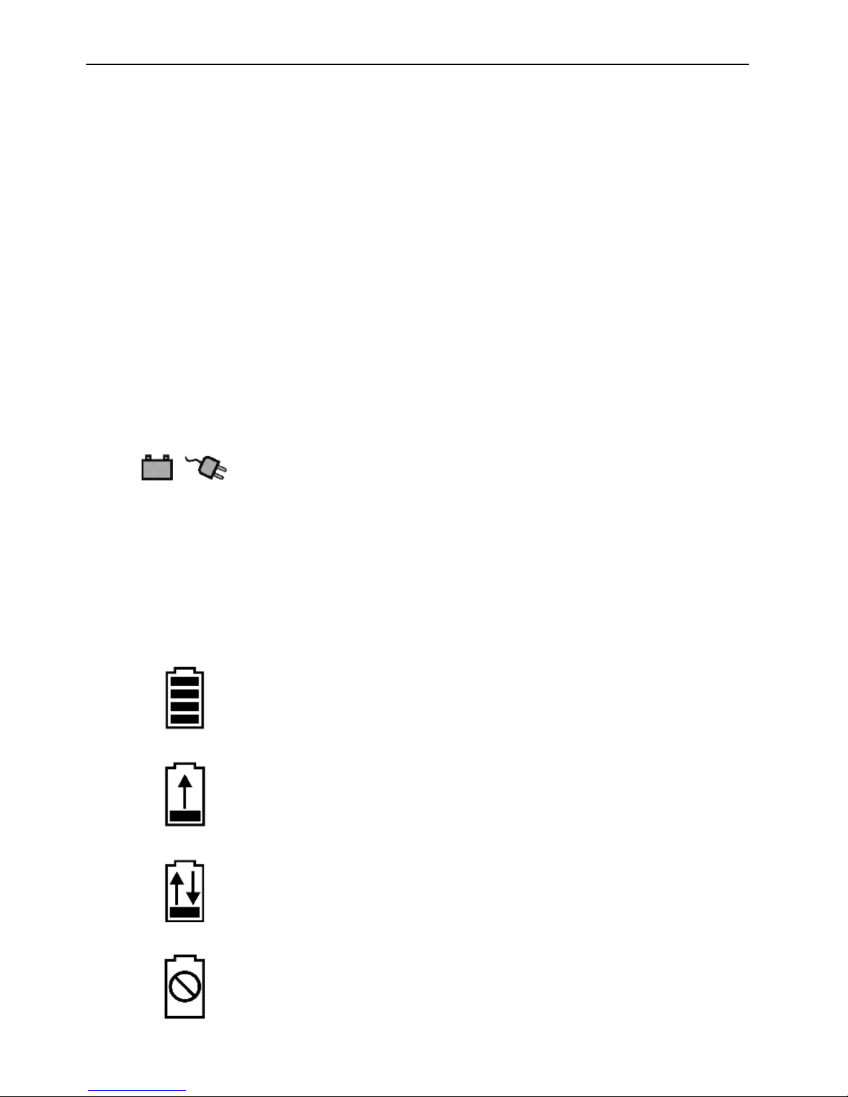
• Operating display
"DEVICE READY"
In stand-by mode, the green LED is lit above the
"battery / mains" symbol.
• Status display
The status displays below the charging bays refer to the corresponding batteries
inserted above it and display the current status of this charging bay when batteries
are inserted:
"ACCU READY"
End of charging cycle, the battery pack can be removed
for use.
"CHARGING"
The charging cycle is active.
"CONDITIONING"
The conditioning cycle is active.
"FAILED"
A battery failure has caused an interruption of the
charging / conditioning cycle.
Page 8

Page 8 User Manual "MBSS"
9. Symbols
"Refer to the User Manual"
Read this user manual before starting the device.
Note the safety instructions !
"CE mark"
CE mark by manufacturer according to
EC guideline MDD 93/42/EWG.
10. Initial Operation
Connect the "MBSS" battery charger to a safe mains power supply or the power
supply of the vehicle by using the connecting cables supplied with the device. Please
refer to section 6 of the user manual for technical specifications.
For mains power supply set mains switch to position "I". In stand-by mode, the
green LED will illuminate.
Warning !
The mains switch is for use with the mains power supply only. It has no effect on
any low voltage power supply that may be connected to the device. The device is set
for priority mains operation in case both power supply connectors are used. In the
case a low voltage power supply is used with the device, such power supply can
only be turned off by disconnecting the low voltage cable.
Note
In stand-by mode, power consumption of the "MBSS" is very low. Therefore, the
MBSS is suited for permanent stand-by mode in emergency vehicles.
Page 9

User Manual "MBSS" Page 9
11. Charging the batteries
Insert a battery into one of the charging bays. You may choose any charging bay, but
the clip of the battery must always face the external side of the "MBSS".
• The securing clip must snap into position audibly. Always make sure the battery is
properly secured.
• Verify correct insertion of the battery by ensuring that "CHARGING" is displayed
below the charging bay.
• If the "READY" display lights up, the charging cycle is completed.
• Until they are used, the charged batteries may be stored in the charging bays. The
"MBSS" device has an automatic refresh mode. Thus, the batteries will always be
kept fully charged and ready for use.
Caution !
The inserted batteries are secured by a clip. Take the battery out of the charging
bay by pressing the clip at the indented area on the left or right side of the clip,
respectively.
Do not remove the batteries from the charging bay, if the "CONDITIONING" process
has not yet been terminated, as indicated by the "READY" message.
Note
In case a battery with a higher rest charge is inserted while the "MBSS" is still
working on another bay where a battery has been inserted with a lower rest charge,
the battery with the higher remaining charge will be charged first.
"Smart Batteries" will be treated preferentially. Conditioning will always be postponed for charging.
Average duration of charging
The duration of the charging process of the batteries depends on the nominal capacity
and the remaining charge. To estimate the expected charge time, the following data
can be used:
- "Fastpak NiCd" with 1.0 Ah: approx. 25 minutes
- "Fastpak 2 NiCd" with 1.2 Ah: approx. 30 minutes
- "Lifepak NiCd" with 1.7 Ah: approx. 40 minutes
- "Lifepak NiCd" with 2.4 Ah: approx. 60 minutes
- "Lifepak
®
SLA" with 2.5 Ah: approx. 150 minutes
Page 10

Page 10 User Manual "MBSS"
12. Conditioning the batteries
In "CONDITIONING" mode, the batteries will be charged in a special way to avoid the
so-called memory effect. Initially, batteries will be completely charged and immediately
discharged. Then, the batteries will be charged again. Whenever necessary, a "Smart
Battery" will ask for this mode after insertion into the "MBSS".
"MBSS" firmware releases V1.6 or later can be switched to "CONDITIONING" mode
manually:
• Insert a battery into one of the charging bays as described in section 10 above.
• Remove the battery from the charging bay when the "CHARGING" display
illuminates. The display will change to "CONDITIONING" for about 3 seconds.
• Insert the battery again while "CONDITIONING" is displayed.
Note
If you want to disregard the conditioning of a battery, take the battery out of the
charging bay while "CONDITIONING" is displayed. The display will change to
"CHARGING" for about 3 seconds. Reinsert the battery again while "CHARGING" is
displayed.
If conditioning been requested at intervals, the "CONDITIONING" mode will be
initiated, if batteries are inserted again.
Caution !
The inserted batteries are secured by a clip. Take the battery out of the charging
bay by pressing the clip at the indented area on the left or right side of the clip,
respectively.
Do not remove the batteries from the charging bay, if the "CONDITIONING" process
has not yet been terminated, as indicated by the "READY" message.
Average duration of conditioning
The duration of the conditioning process of the batteries depends on the nominal
capacity and the remaining charge. To estimate the expected conditioning time, the
following data can be used :
- "Fastpak NiCd" with 1.0 Ah: approx. 2 hours
- "Fastpak2 NiCd" with 1.2 Ah: approx. 2 hours
- "Lifepak NiCd" with 1.7 Ah: approx. 3 hours
- "Lifepak NiCd" with 2.4 Ah: approx. 4 hours
- "Lifepak
®
SLA" with 2.5 Ah: approx. 6 hours
Page 11

User Manual "MBSS" Page 11
13. Errors
In case of premature interruption of the charging process the following error codes
will be displayed and the causes will be indicated by different LEDs. In addition to
the display, an acoustic alarm will sound for approximately 5 seconds.
Error I
All LEDs flashing => "Device Error"
- Interruptions or variations in power supply
Solution: Switch the device off by disconnecting it from the power supply
and reconnect it after 10 seconds.
- Overheating, e.g. when exposed to direct sunlight
Solution: Disconnect the device from the power supply and let it cool
for some minutes. Restart the device.
Error II
LED "Failed" illuminates => "Battery Error"
- Data communication error between battery and "MBSS"
Solution: Take the battery out of the bay and try again after 10 seconds.
If, after this interval, the error occurs again, the battery may
be overheated, damaged or unserviceable because of its age.
Error III
Both LEDs "FAILED" flashing => "Power Supply Voltage Low"
- Power supply voltage low, e.g. because of low voltage of vehicle battery.
Solution: Take the battery out of the bay or disconnect the "MBSS"
from the power supply.
Page 12

Page 12 User Manual "MBSS"
14. Troubleshooting
• No function, operation, LED does not illuminate.
- Check connection to power supply.
- Set mains switch to position "I"
- Disconnect mains and change both fuses. Disconnect the panel above the
mains switch first. Use fuses type "T1,0AL / 250V" only.
• Operation LED illuminates, but the device does not work after insertion of
battery.
- The battery has not been inserted properly. Apply slight pressure to the
battery until the securing clip audibly clicks into place.
- An internal safety fuse has blown. Disconnect the device from the power
supply for approximately 20 seconds before turning the device on again.
- An internal safety fuse has blown after the maximum operating temperature
has been exceeded. Allow the device to cool down.
In case none of the recommended solutions proves successful, there is probably
a fault in the device. Please contact your customer service representative.
Page 13

User Manual "MBSS" Page 13
15. Cleaning and disinfection
Disconnect the power supply before cleaning the device.
Clean the outer surfaces of the device with a soft, non-abrasive cloth. For thorough
cleaning use soapy water or an isopropyl alcohol-wipe. Make sure that water or
cleaning fluid does not seep into the device through slits or connectors.
Use commercially available antiseptics to disinfect the device. Make sure the cleaning
fluid does not react with the housing material.
Warning !
The device is not suitable for sterilisation !
16. Maintenance and Safety Test
The "MBSS" is maintenance free.
The manufacturer recommends safety tests at 24 month intervals. Please document
the safety tests as required by the law.
17. Packaging
The "MBSS" is supplied in a reusable cardboard box. Please store the packaging for
later use, i.e. in case of service, maintenance or repair.
Please refer to the packaging instructions on the inside of the cardboard box.
18. Disposal
At the end of the product’s lifetime please dispose of the device in accordance with
the applicable legal regulations.
Prior to disposal, please clean and disinfect the device.
For further information on disposal in accordance with pertinent environmental
regulations, please contact the manufacturer, AD Elektronik GmbH.
Page 14
Page 14 User Manual "MBSS"
19. Installation and use of wall mount for MBSS
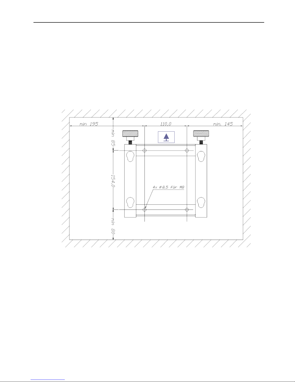
• Installing the wall mount
- Secure the supplied wall mount vertically in a place where the underground is
stable enough to support the mount. This applies to emergency vehicles in
particular.
- The required dimensions for installing the mount are supplied in the drawing
below. Please abide to the minimum distance requirements in all directions.
Otherwise, the device may not operate properly.
• Installation instructions
- The 4 studs on the back of the "MBSS" fit into the 4 holes of the wall mount.
Insert the studs into the slightly bigger openings and then push the device
downwards while applying slight pressure.
- Secure the device by tightening both safety screws. Please make sure the
device is properly secured.
- Connect the device to the required power source according to section 6 of the
user manual.
• Instructions for removing the wall mount
- Disconnect the device from the power source
- Remove both safety screws by removing them about 15 millimetres.
- Push the device upwards and pull it out of the wall mount towards you.
Page 15

User Manual "MBSS" Page 15
20. Specifications
Dimensions:
Weight:
30 cm x 20 cm x 10 cm without mains plug and wall mount.
2.9 kg without battery and wall mount.
Mains
- Connection:
- Voltage:
- Power consumption:
- Fuse:
- Protection Class:
By IEC plug
100 V~ ... 240 V~ (AC), 50 Hz ... 60 Hz
Operation (Charge) max. 80 W, Stand-by approx. 5 W
Fuse 2 x T 1.0AL / 250V
Class I
Battery
- Connection:
- Voltage:
- Current:
- Fuse (Recommended):
- Class:
Low Voltage Connector "12V"
11.0 V = ... 16.0V = (DC)
Operation (Charge) max. 6 A, Stand-by approx. 30 mA
Fuse 8A via vehicle distributor
Class III
Battery Types:
Medtronic - Physio Control, type
"Fastpak®", "Fastpak2®", "Lifepak®NiCd" and "Lifepak®SLA"
Charging Algorithm
- NiCd batteries:
- SLA batteries:
Pulse charging algorithm, microcontroller-operated
Constant current / voltage charging, microcontroller-operated
Features:
Automatic battery detection and parameter settings
Automatic trickle charge and conditioning mode
Temperature- and time control for overcharge protection
Priority charging
Environmental
- Operation
Temperature:
Humidity:
- Transport and Storage
Temperature:
Humidity:
- Protection:
+0 °C ... +40 °C
35 % ... 80 %, non condensing
-30 °C ... +70 °C
15 % ... 90 %, non condensing
IP X1
Manufacturer:
AD Elektronik
GmbH
D-35583 Wetzlar/Germany, Sudetenstr. 7-9
Telefon
+49 (0)6441/9258-0 Fax +49 (0)6441/9258-19
Page 16
Page 16 User Manual "MBSS"
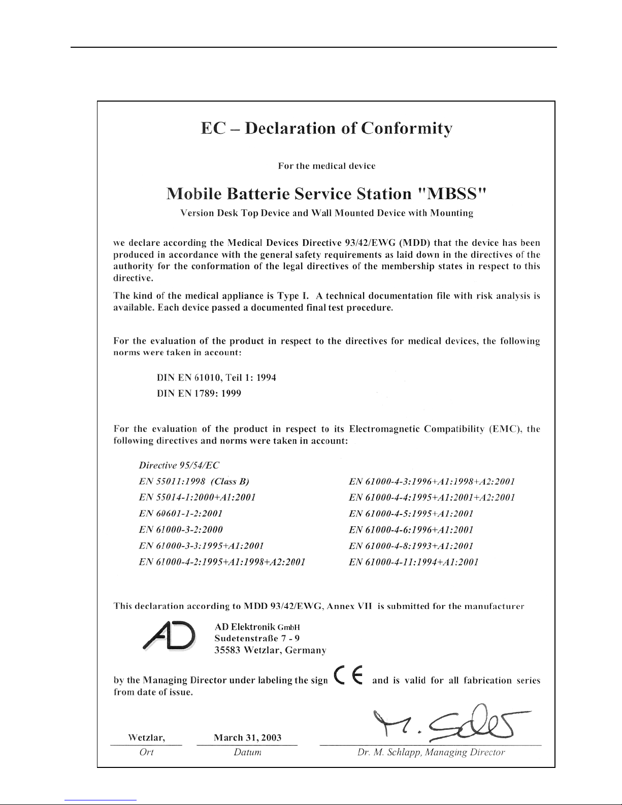
21. EC Declaration of Conformity
 Loading...