

Page 1
Mercury Hub User Guide
Mercury 6-5 M/E Installation guide
Mercury Hub
User Guide
PR0018 (Mains Powered)
PR0017 (Mercury Controller Powered)
Ensure that all power is
switched off before
installing or mainta ining
this product
Revision 1.5 Page 1 of 6
Page 2

Mercury Hub User Guide
Mercury 6-5 M/E Installation guide
Table of Contents:
THE MERCURY HUB..........................................................................................................................................3
Description.........................................................................................................................................................3
Front View ..........................................................................................................................................................3
Rear View............................................................................................................................................................3
Top View.............................................................................................................................................................4
Connection to Mercury Controllers:................................................................................................................4
RS232 Lead Lengths.......................................................................................................................................4
Connection to other IP equipment...................................................................................................................4
Connection to another Mercury Hub or Other Ethernet Hub/switch............................................................4
Connection to a Data Manager/Director..........................................................................................................4
10 Base T connectors .......................................................................................................................................5
Network ID..........................................................................................................................................................5
ID for equipment with rotary switch’s.............................................................................................................5
SPECIFICATION.................................................................................................................................................6
Power requirements:.........................................................................................................................................6
Mounting.............................................................................................................................................................6
RS232 Cable Lengths........................................................................................................................................6
Ethernet Cable lengths .....................................................................................................................................6
Ensure that all power is
switched off before
installing or mainta ining
this product
Revision 1.5 Page 2 of 6
Page 3

Mercury Hub User Guide
Mercury 6-5 M/E Installation guide
The Mercury Hub
From Resource Data Management
Description
The Mercury Hub is a device that allows up to 10 RDM controllers to be connected to an IP network, with out
the need for individual IP Futura modules. The Hub can be mains powered, or powered from 2 connected
Mercury controllers. There are 10 RS232 connections for linking to Mercury controllers, 2 standard ethernet
hub (10baseT) connections for other network devices and a dedicated ethernet Uplink port.
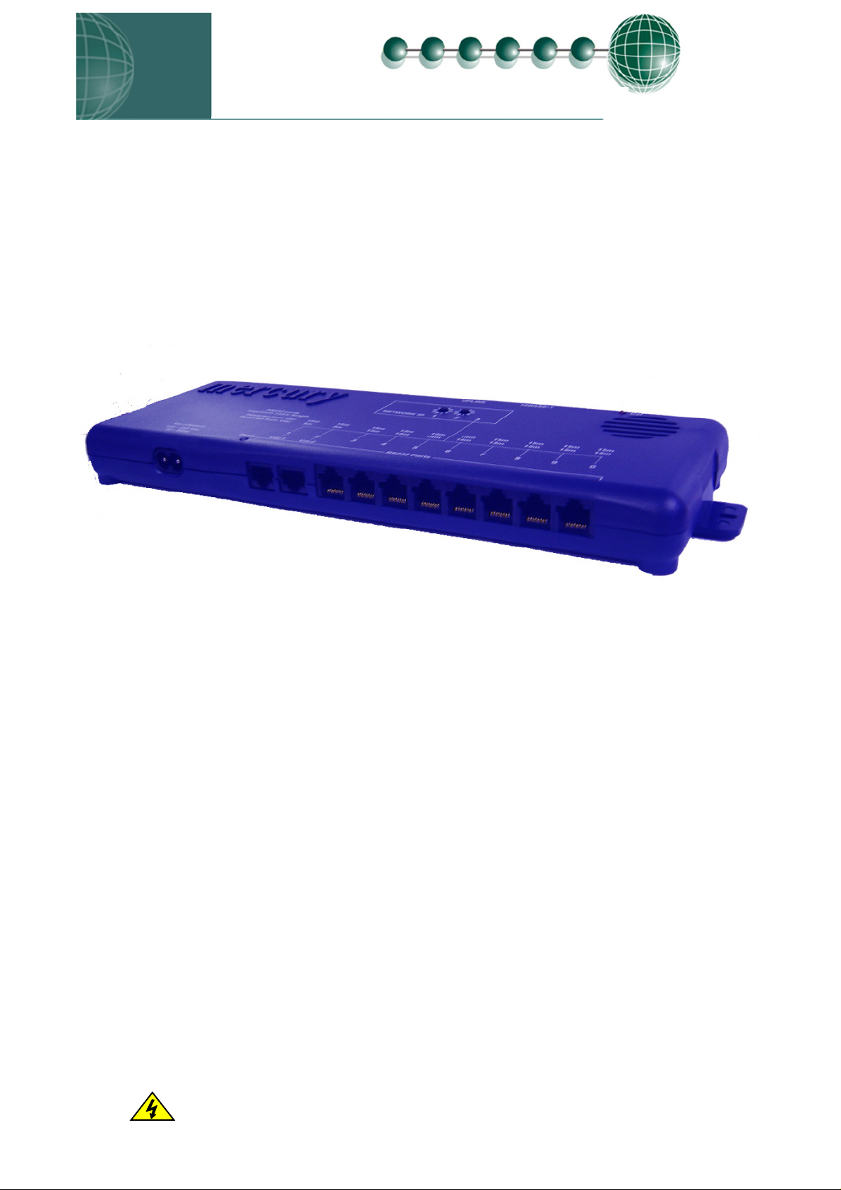
Front View
Rear View
Mains connector
10 x RS232 Ports for direct connection to RDM controllers
Ports 1 & 2 are used to power the Hub in the non-mains version
2 x IP ports
Uplink IP port
Ensure that all power is
switched off before
installing or mainta ining
this product
Revision 1.5 Page 3 of 6
Page 4

A
Mercury Hub User Guide
Mercury 6-5 M/E Installation guide
Top View
ddress selection switches
Collision LED
UPLINK
10BASE-T
Col
1
NETWORK ID
1
0
0
9
9
12
3
Vac (Option)
100 - 250 Vac
50 - 60Hz
Power
Power
Vdc
1 2 3 4 5 6 7 8 9 0
Rs232 Ports
Power On LED
Connection to Mercury Controllers:
Using a standard CAT5 patch lead, connect the serial output of the RDM Cont roller to one of the RS232 ports
of the Mercury Hub.
RS232 Lead Lengths
For mains powered hubs, patch lead maximum length must not exceed 15 metres. (ports 1 - 10)
For Mercury powered hubs, inputs 1 and 2 patch leads must not exceed 5 metres, port s 3 - 1 0 must not
exceed 15 metres.
The 3-character address that will be seen on the system front end is determined by the position of the two
Network ID rotary switches and the port the controller has been connected to.
Connection to other IP equipment
Use a standard CAT5 patch lead to connect other IP equipment to the Mercury Hub (such as a Futura IP
module) into the 10Base T ports 1 or 2.
Connection to another Mercury Hub or Other Ethernet Hub/switch
Use a standard CAT5 patch lead from the Uplink port into a standard IP port on the next Hub.
Connection to a Data Manager/Director
Use a standard CAT5 patch lead and connect the Data Manager or Data Director to one of the two 10 Base T
ports.
Ensure that all power is
switched off before
installing or mainta ining
this product
Revision 1.5 Page 4 of 6
Page 5

Mercury Hub User Guide
Mercury 6-5 M/E Installation guide
10 Base T connectors
The three 10Base T connectors have 2 leds on them: The green LED; when static, indicates that the
connection to the device is good, the green LED then flickers when data is being transmitted.
The amber LED indicates there is an error or fault on that channel.
Network ID
The 3-character network ID is made up from the positions of the 2 rotary switches and the RS232 connector
number. We recommend that the 2 rotary switches are set to the Bay number and that the case sections are
plugged into their corresponding RS232 port numbers.
E.g. Bay 10 case 2: The 2 rotary switches set to "1" and "0", controller plugged into port 2. The ID then is seen as "102" at the
system front end.
NETWORK ID
1
1
0
0
9
9
12
3
Vdc
1 2 3 4 5 6 7 8 9 0
Controller
at position 2
Note that case number 10 would plug into RS232 port 0 (right most port) and come through as "100".
ID for equipment with rotary switch’s.
For RDM products that use the 3 rotary switch’s for the network ID (such as Powertrays), the ID will follow
what is set on the controller local switch’s and NOT the port position on the Hub.
Ensure that all power is
switched off before
installing or mainta ining
this product
Revision 1.5 Page 5 of 6
Page 6

Mercury Hub User Guide
Mercury 6-5 M/E Installation guide
Specification
Power requirements:
Supply Voltage Range: 100 - 240 Vac ±10% (Mains version)
Supply Frequency: 50 - 60 Hz (Mains version)
OR 2 x Mercury Controllers connected to ports 1 and 2
Maximum supply current: 500 mAmps
Typical supply current: <100 mAmps
Operating temperature range: +5
Operating Humidity: 80% maximum
Storage temperature range: -20
Environmental: Indoor use at altitudes up to 2000m, Pollution Degree 1,
Installation Category II.
Voltage fluctuations not to exceed ±10% of nominal voltage
Size: 300mm (L) x 35mm (H) x 110mm (W)
Weight: 300 Grams
Safety: EN61010
EMC: EN61326; 1997 +Amdt. A1; 1998
Ventilation: There is no requirement for forced cooling ventilation
Class 2 Insulation: No protective Earth is required and none should be fitted.
The host equipment must provide a suitable external over-current protection device such as: Fuse: 1A 240 Vac Antisurge (T) HRC conforming to IEC 60127
Or MCB: 1A, 240 VAC Type C conforming to BS EN 60898
Mounting
There is a fixing lug at each end of the Hub, with hole centres 317 mm apart. Use typically Number 6 x 1”
Pan head screw with 6mm washer, torque down to 1.5 Newton metres.
RS232 Cable Lengths Port number Main Powered Hub Mercury Powered Hub
1 15 metres 5 metres 2 15 metres 5 metres 3 15 metres 15 metres 4 15 metres 15 metres 5 15 metres 15 metres 6 15 metres 15 metres 7 15 metres 15 metres 8 15 metres 15 metres 9 15 metres 15 metres 0 15 metres 15 metres
Ethernet Cable lengths Port number Main Powered Hub Mercury Powered Hub
1 Refer to Cat5 standard Refer to Cat5 standard
2 Refer to Cat5 standard Refer to Cat5 standard
Uplink Refer to Cat5 standard Refer to Cat5 standard
0
C to +500C
0
C to +650C
Ensure that all power is
switched off before
installing or mainta ining
this product
Revision 1.5 Page 6 of 6
 Loading...