

Page 1
Addonics
TECHNOLOGIES
Z USB3.0 / eSATA Combo Drive Enclosure
for SATA or IDE Hard drive or Optical drive
Model: ZESSIU3CS
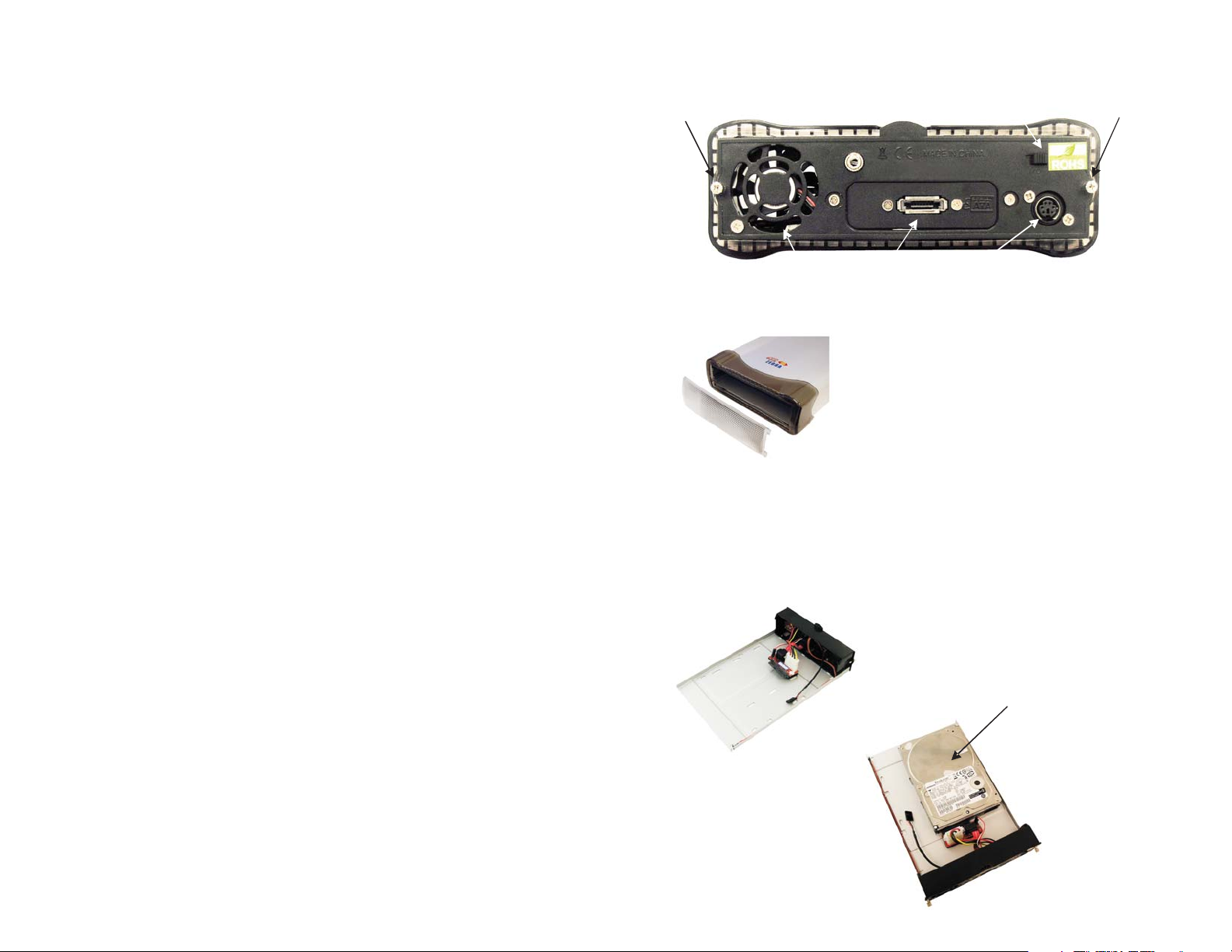
Enclosure Overview
Screw 1 Screw 2
Fan
eSATA Port
Switch
Power
Connector
Removing the front panel
You can remove the front panel of the enclosure to
access the drive drawer of the optical drive.
User’s Guide
FCC Warning Statement
This equipment has been tested and found to comply with the limits for a cl ass B digital
device pursuant to Part 15 of the FCC rules. These limits are designed to provide
reasonable protection against harmful interference in a residential installation. This
equipment generates, uses and can radiate radio frequency energy. If not installed and
used in accordance with the instructions, it may cause harmful interference to radio
communications. However, there is no guarantee that interference will not occur in a
particular installation. If the equipment does cause harmful interf erence to radio or
television reception, which can be determined by turning the equipment on and off, the user
is encouraged to try and correct the interference by one or more of the following
suggestions.
Reorient or relocate the receiving antenna
Increase the distance between the equipment and the receiver
Connect the equipment to a different power outlet other than the one where receiver is
connected
Consult a certified television or radio technician
TECHNICAL SUPPORT
Phone: 408-453-6212
Hours: 8:30 am - 6:00 pm PST
Email: http://www.addonics.com/support/query/
Step 1
Loosen the two screws from the rear panel. Pull out the interior tray from the
enclosure.
Step 2
A. Installing a 3.5” SATA hard drive
SATA hard
drive
Slide in the 3.5”
SATA hard drive
and secure on the
tray using screws.
Page 2
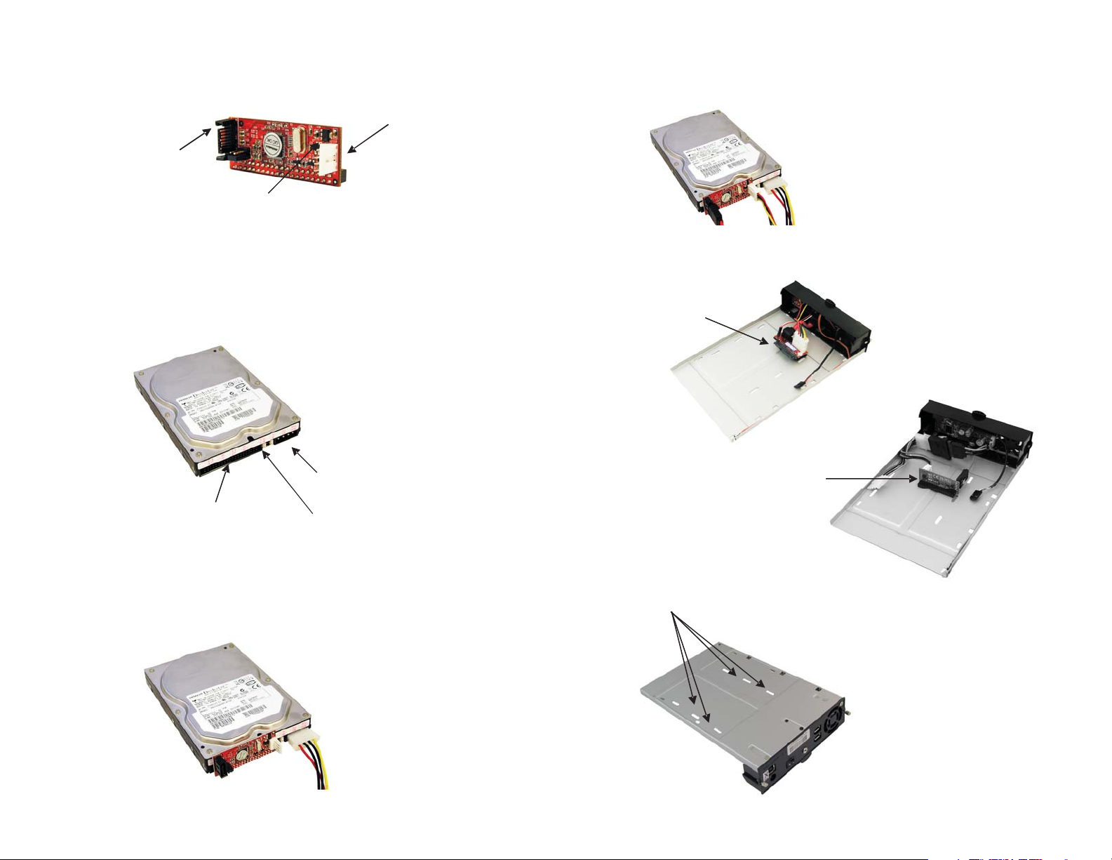
B. Installing a 3.5” IDE hard drive
The Z USB3.0 / eSATA combo drive enclosure comes with an IDE to
SATA converter.
40-pin IDE Connector
SATA Port
4-Pin Floppy
Power
Note: It is required to set up the IDE hard drive you are connecting to
the converter as a MASTER device.
1. Locate the 40-pin IDE connector of your IDE drive.
4-pin Molex
Power Connector
40-pin IDE Connector
Master or Slave
Jumper Settings
4. At the other end of the Y-power cable is the 4-pin floppy power connector
which you connect to the converter. Now connect the SATA cable to the
SATA port on the converter.
5. Disconnect the SATA board from the drive enclosure. Then connect the
SATA cable to the SATA port on the IDE to SATA converter
SATA board
ADSAIDE
IDE to
SATA converter
2. Connect the converter board to the IDE connector of the hard drive.
3. Using the provided Y-power cable, connect the 4-pin Molex
connector to the power connector on the hard drive. This will
provide power to the hard drive.
Step 3
Use the enclosed screws to secure the hard drive to the tray.
Screw holes
 Loading...