

Page 1
T E C H N O L O G I E S
User Guide
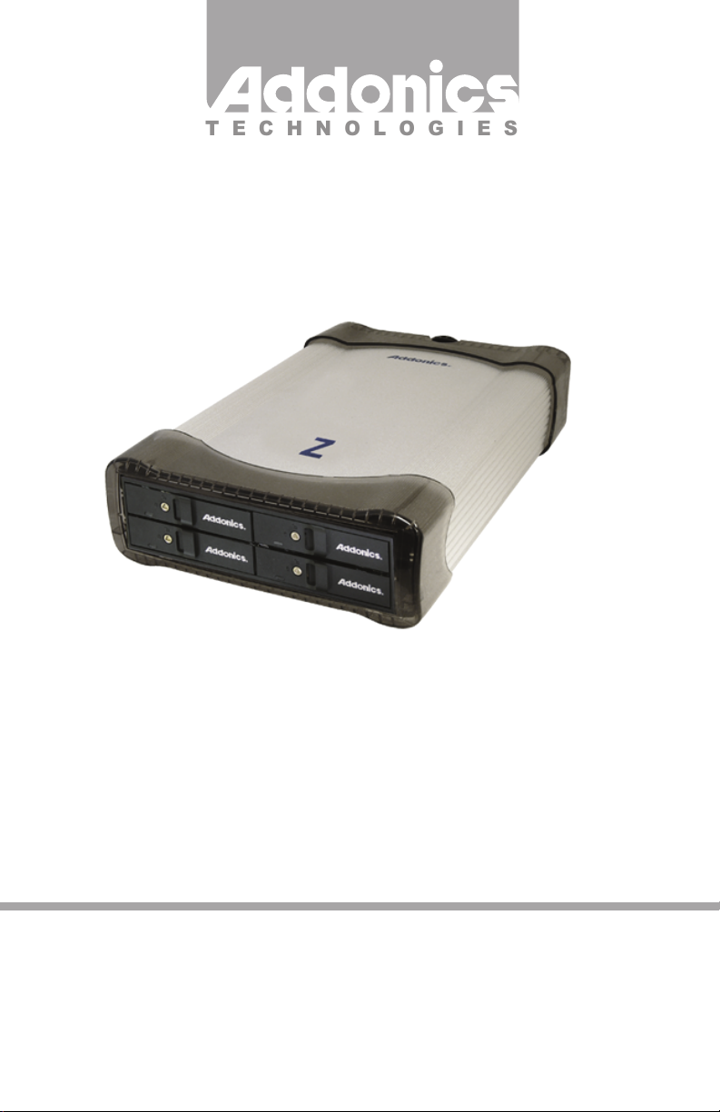
Z Snap-In Disk Array
(Z4SNHU3)
www.addonics.com
v8.1.11
Technical Support
If you need any assistance to get your unit functioning properly, please have your
product information ready and contact Addonics Technical Support at:
Hours: 8:30 am - 6:00 pm PST
Phone: 408-453-6212
Email: http://www.addonics.com/support/query/
Page 2
Installation
1. Install drives as described in the Disk Installation section.
2. Connect the AC power adapter’s input to a wall outlet and the output cable to
the Z Disk Array’s power connector.
3. Connect either the USB 3.0 or eSATA cable from the Z Disk array to the computer.
4. Configure the Port Multilpier as described in the Port Multiplier section.
5. Turn on the unit using the power switch on the back next to the power
connector (see note).
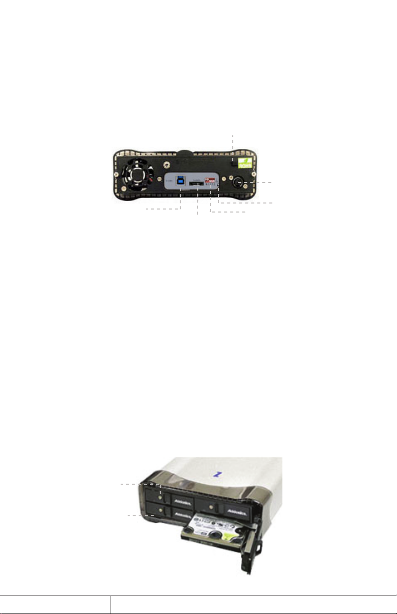
Power Switch
Power
Connector
USB 3.0 Port
eSATA connector
RAID Mode button
Dip switch
Disk Installation
1. Be sure the lock on each drive door is unlocked. If not, use the key that came with the
Z Snap-In Disk Array to unlock the drive door. Pull on the door lever to swing open the
drive door all the way.
2. Slide a 2.5” SATA hard drive into the drive slot with the drive connector side facing in
and the label side up. The drive should slide all the way into the slot with very little
resistance. Forcing the drive into the slot will cause permanent damage to the drive or the
Snap-In enclosure.
3. Once the drive is all the way into the drive slot, close the door all the way till the drive
door latches securely. This will engage power and data connection with the hard drive.
You may lock the drive door with the key.
4. To remove the hard drive from the enclosure, simply follow the step 2 – 3 in reverse.
Note: Hot swapping the drives must be supported by the host adapter. Powering the
cabinet on or off or inserting or removing drives when connected to a host adapter that
does not support hot swapping will cause undesirable results.
Key locks to
lock drive door
LEDs for
drive activity
www.addonics.com Technical Support (M-F 8:30am - 6:00pm PST) Phone: 408-453-6212 Email: www.addonics.com/support/query/
Page 3
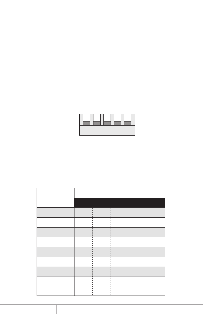
Port Multiplier
Default factory DIP Switch setting:
SW1 – RAID Setting DIP Switch
BZS – Error buzzer function
EZ – Automatic rebuilding to spare drive (one of the drives on the raid is set as a
spare). If EZ is ENABLED anda drive failure occurs, the spare will
automatically act as a drive replacement and rebuilding will automatically
start.
M2 – RAID mode 2
M1 – RAID mode 1
M0 – RAID mode 0
OFF
OFF
OFF
OFF
OFF
SW1
1 2 3 4 5
BZS EZ M2 M1 M0
1. Error buzzer function is ENABLED (BZS) when dip switch is in OFF position
2. Auto-rebuilding to spare drive is DISABLED (EZ)
3. Individual drive mode is ENABLED (M0~M2)
Dip Switch Settings
Raid Mode 1 2 3 4 5
Individual Drive
(Factory Default)
0
1 and 10
3
5
Clone
Large
OFF
OFF
OFF
OFF
OFF
OFF
OFF
Enable
ERR Buzzer
Function
OFF
OFF
OFF
OFF
OFF
OFF
OFF
AutoRebuilding
to Spare
Drive
OFF
ON
ON
ON
OFF
OFF
ON
Port Multiplier Mode
OFF
ON
ON
OFF
ON
ON
OFF
OFF
ON
OFF
OFF
OFF
ON
ON
www.addonics.com Technical Support (M-F 8:30am - 6:00pm PST) Phone: 408-453-6212 Email: www.addonics.com/support/query/
Page 4

Setting the RAID Mode:
1. For Windows users, install the JMicron HW RAID Manager located on the
SATA Controller CD. In the CD, go to Configuration Utilities > JMB393. This
manager can be use to create and monitor the status of the RAID volume.
It is recommended to use the default factory RAID DIP switch setting when
using the JMicron HW RAID Manager.
2. Modify the RAID mode on the 5-port HPM-XU using DIP switch
Recommended to be used on operating system without JMicron HW RAID
Manager support like Linux, Mac & Solaris. Windows users can also use the
procedure below.
Note: Steps A to D need to be performed each time the raid mode is modified.
a. Set the DIP switch to factory default setting.
SW1
b. Press the RAID setting button with a ball point pen.
c. While pressing the RAID setting button turn on the system power
where the HPM is connected. The buzzer will sound while holding the
RAID setting button. Release it after at least 5 seconds for hardware
initialization. A single beep will be heard to indicate initialization is
completed. The above steps act as a reset.
d. Power off the system power.
e. On the DIP switch, change (M0 to M2) setting to the
desired RAID mode using the diagram below.
All settings on the diagram shows
• Error buzzer function is ENABLED
• EZ function is DISABLED.
1 2 3 4 5
BZS EZ M2 M1 M0
www.addonics.com Technical Support (M-F 8:30am - 6:00pm PST) Phone: 408-453-6212 Email: www.addonics.com/support/query/
Page 5

RAID 0 Mode
OFF
OFF
ON
ON
ON
Clone Mode
OFF
OFF
OFF
ON
ON
SW1
SW1
SW1
1 2 3 4 5
BZS EZ M2 M1 M0
RAID 1& RAID 10 Mode
OFF
OFF
ON
ON
OFF
1 2 3 4 5
BZS EZ M2 M1 M0
RAID 3 Mode
OFF
OFF
ON
OFF
OFF
1 2 3 4 5
BZS EZ M2 M1 M0
RAID 5 Mode
SW1
SW1
SW1
1 2 3 4 5
BZS EZ M2 M1 M0
Large Mode
OFF
OFF
ON
OFF
ON
1 2 3 4 5
BZS EZ M2 M1 M0
Individual Drives Mode
OFF
OFF
OFF
OFF
OFF
1 2 3 4 5
BZS EZ M2 M1 M0
OFF
OFF
OFF
ON
OFF
SW1
1 2 3 4 5
BZS EZ M2 M1 M0
www.addonics.com Technical Support (M-F 8:30am - 6:00pm PST) Phone: 408-453-6212 Email: www.addonics.com/support/query/
Page 6

RAID Setting Notes:
RAID 1& RAID 10 Mode
SW1
When 4 drives are connected to the HPM-XU, the 4 drives will be
configured as a 4-drive RAID10 array.
1 2 3 4 5
BZS EZ M2 M1 M0
Clone Mode
SW1
f. Press the RAID setting button with a ball point pen.
g. While pressing the RAID setting button turn on the system power
where the HPM is connected. The buzzer will sound while holding the
RAID setting button. Release it after at least 5 seconds for hardware
initialization. A single beep will be heard to indicate initialization is
completed.
1 2 3 4 5
BZS EZ M2 M1 M0
When 2 drives are
connected to the HPM-XU,
and DIP switch is set to this
setting, the 2 drives will be
configured as a 2-drive
RAID1 array.
Clone’s action is similar to
RAID1. However, all of the
hard drives will be mirrored.
Clone mode is useful
especially when users like
to copy data from a source
hard drive to the drives
connected to the HPM-XU.
h. Verify if the RAID array is detected by the system.
i. If the 5-port HPM-XU is connected to the motherboard onboard
SATA, on the CMOS setup utility, the raid array will display as
“Addonics H/W RAID5” if setup as a RAID5 array.
j. If the 5-port HPM-XU is connected to an eSATA host controller card,
on the RAID BIOS, the raid array will display as “Addonics H/W
RAID0” if setup as a RAID0 array.
k. If booted into Windows, in Disk Drives under Device Manager, the
raid array will display as “Addonics H/W LARGE” if setup as a
LARGE array.
l. Once raid array is verified, you can set the buzzer either ON or OFF.
www.addonics.com Technical Support (M-F 8:30am - 6:00pm PST) Phone: 408-453-6212 Email: www.addonics.com/support/query/
Page 7

Notes on Spare Drives using the Easy RAID Setting (EZ)
When EZ function is ENABLED, the auto-rebuilding to spare drive is automatic.
The degraded RAID group will start rebuilding automatically by using the existing
spare drive.
* Spare drive can be either plugged after RAID building or a new drive can be plug
as the spare drive when RAID rebuild is required.
When will rebuild action start?
• When the raid fails and EZ is enabled, the HPM-XU will
automatically rebuild the RAID group using the spare.
• When the raid fails and EZ is disabled, the HPM-XU will NOT
rebuild the raid group unless you install a good drive to replace the
failed drive.
CONTACT US
www.addonics.com
Phone: 408-573-8580
Fax: 408-573-8588
Email: http://www.addonics.com/sales/query/
 Loading...