

Page 1
Addonics
T E C H N O L O G I E S
Storage Tower
ST4IDEU2, ST4SAML, ST5X1PM, ST5XHPM,
ST4US, ST4ESA, ST6ESA, ST5ESAIUS, STMPC, STBTO
ST4IDEU2-B, ST4SAML-B, ST5X1PM-B, ST5XHPM-B,
ST4US-B, ST4ESA-B, ST6ESA-B, ST5ESAIUS-B, STMPC-B
User’s Guide
Version 1.0
FCC Warning Statement
This equipment has been tested and found to comply with the limits for a class B digital
device pursuant to Part 15 of the FCC rules. These limits are designed to provide
reasonable protection against harmful interference in a residential installation. This
equipment generates, uses and can radiate radio frequency energy. If not installed and
used in accordance with the instructions, it may cause harmful interference to radio
communications. However, there is no guarantee that interference will not occur in a
particular installation. If the equipment does cause harmful interference to radio or
television reception, which can be determined by turning the equipment on and off, the user
is encouraged to try and correct the interf erence by one or more of the following
suggestions.
Reorient or relocate the receiving antenna
Increase the distance between the equipment and the receiver
Connect the equipment to a different power outlet other than the one where receiver is
connected
Consult a certified television or radio technician
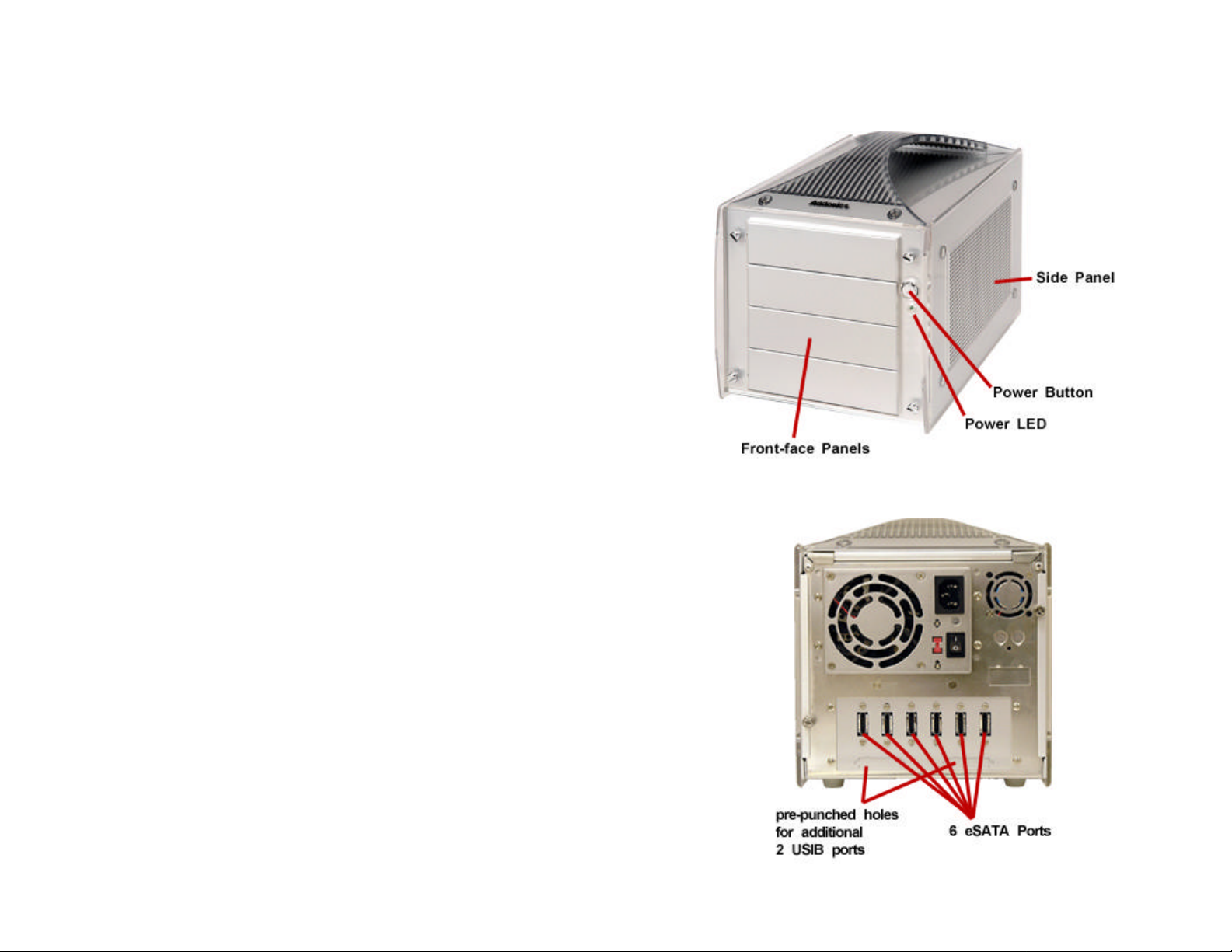
Storage Tower Overview
Model: ST6ESA
Page 2
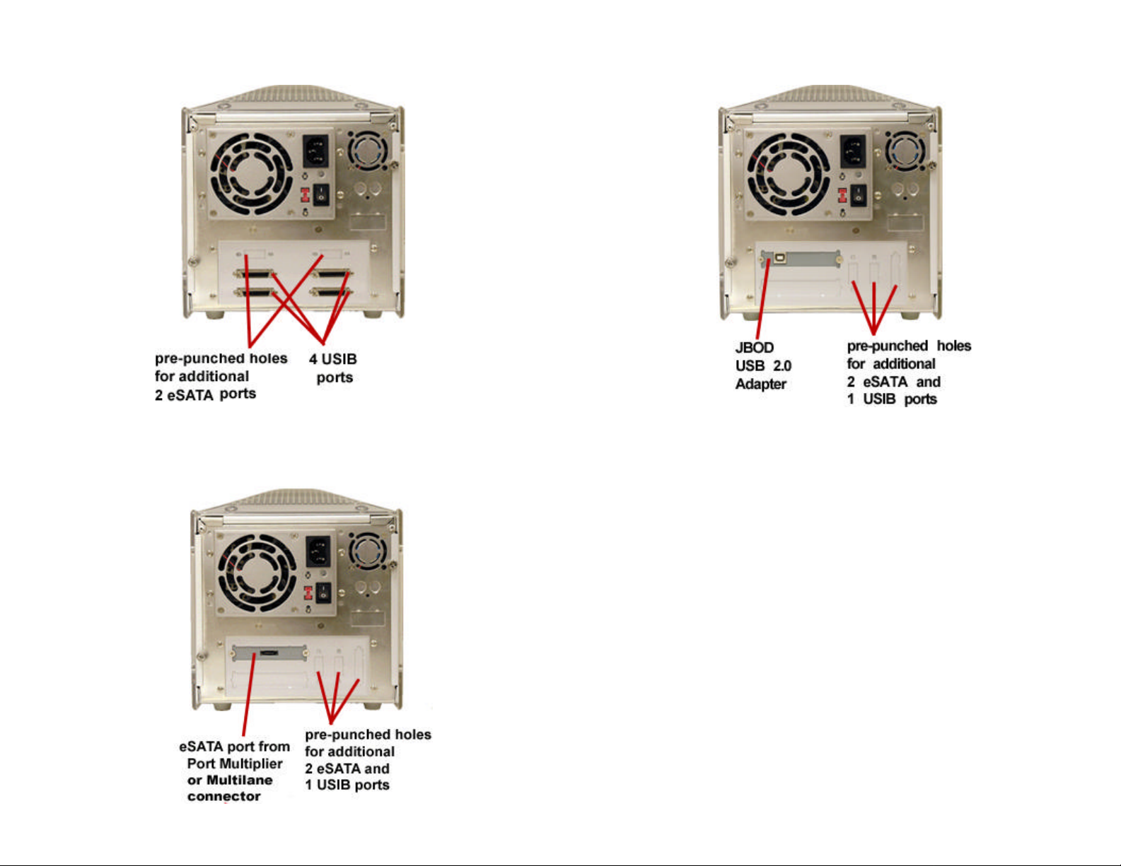
Model: ST4US
ST5X1PM
Model: ST4IDEU2
Model:
Page 3
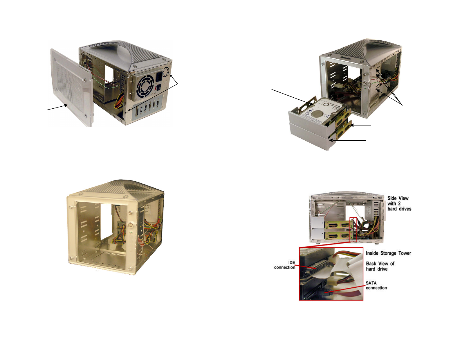
Storage Tower Preparation
•
•
to secure the drives.
•
panel
Side
Side panel
screw
locations
Remove the side panel screws.
• Slide the side panel towards the backside then pull or lift to open.
• To remove the front face panels, unscrew 2 screws on opposite sides
of the 5 ¼” drive bay on the tower
This picture shows the storage tower without both the side panels and front
faceplate.
Sample Installation on the tower using IDE hard drives
IDE Drives
Screw Holes
IDE drives Mounting
Brackets
• Make sure that screws are placed for both sides of the mounting bracket
Front Face Plates
After installing the hard drive, attach the side panels back to the storage
tower.
Page 4
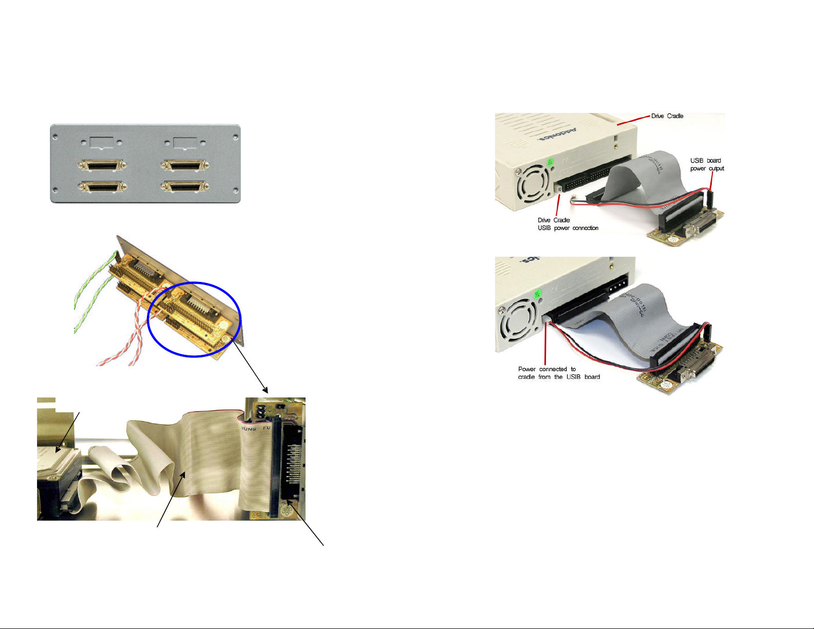
Tower with USIB connector
• Any IDE or ATAPI Storage device can be converted to USB or Firewire
connection via the Addonics USIB interface board and USIB interface cable.
• IDE and ATAPI drives must be set as Master device.
USIB back panel
Inside of the USIB back panel
The USIB setup can do hot swap when Addonics mobile racks are used
• When using an Addonics mobile rack, make sure that the power from the
USIB board is connected to the power input from the cradle. The power to
the Addonics cradle can only go one way.
IDE Device Installation to the USIB Connector
IDE drive
• For USB2 connection, attach the Addonics USB2.0 USIB interface cable to
the USIB connector.
• For Firewire connection, attach the Addonics Firewire USIB interface cable
to the USIB connector.
• When non-Addonics mobile rack is used. The Storage Tower can be
powered down and restarted to swap out hard drive without rebooting the
system when using USB or Firewire interface.
IDE ribbon cable
USIB connector
• To un-mount the drive from the computer using a non-Addonics mobile rack
the USIB cable must be detach from the back of the Storage Tower or the
Storage Tower power must be power off to un-mount the drive from the
computer. The drive will not be hot swappable by turning the switch on and
off from the front of the mobile rack.
Page 5
Tower with eSATA connector
For SATA connection, hot swap feature depends on the controller. All Addonics
SATA controllers support the hot swap feature.
eSATA and USIB back panel
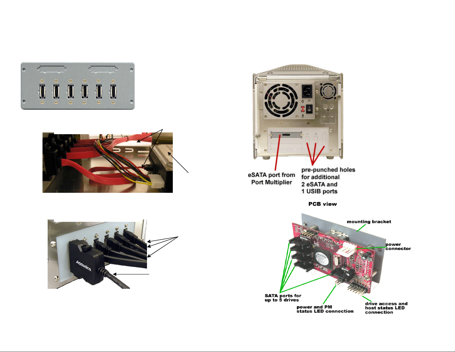
Tower with Port Multiplier
Hot swap feature depends on the SATA controller. All Addonics SATA controllers
support the hot swap feature. Port Multiplier does not work with SATA controller
that has no PM support. Check with your system supplier to confirm the PM
support on your existing SATA port
Inside the Tower
Back of Tower
SATA data cables
SATA Drive
eSATA Data Cable
USIB Interface cable
Page 6

Tower with Hardware Port Multiplier
Note: You need to install the SiI4726 Manager on your system to configure RAID
sets.
RAID configuration is programmed by connecting the hardware port multiplier:
• to one of Addonics’ SATA controllers that has SIL3124 or SIL3132 chip set.
• via USB 2.0 connection (optional Addonics eSATA-USB adapter is required)
After RAID configuration, it is compatible with any SATA controller (RAID or non
RAID)
Software Installation for SiI4726 Manager
A. From the CD start-up menu select SATA RAID Utilities > Other
SATARAID Utilities > Windows 2000/XP/2003/Vista.
B. Unzip the file SiI_4726_Manager_V4.0.0.9.zip on your drive. The folder
name would be SiI4726.
C. To install SiI4726 Manager, double click setup.exe
In SiI4726 Manager, all the drives connected to the
AD5SAHPM-E will show up.
For a complete User’s Guide of SiI4726 refer to our website.
Support > User Guides > SiI4726 Manager User Manual V.26
Page 7
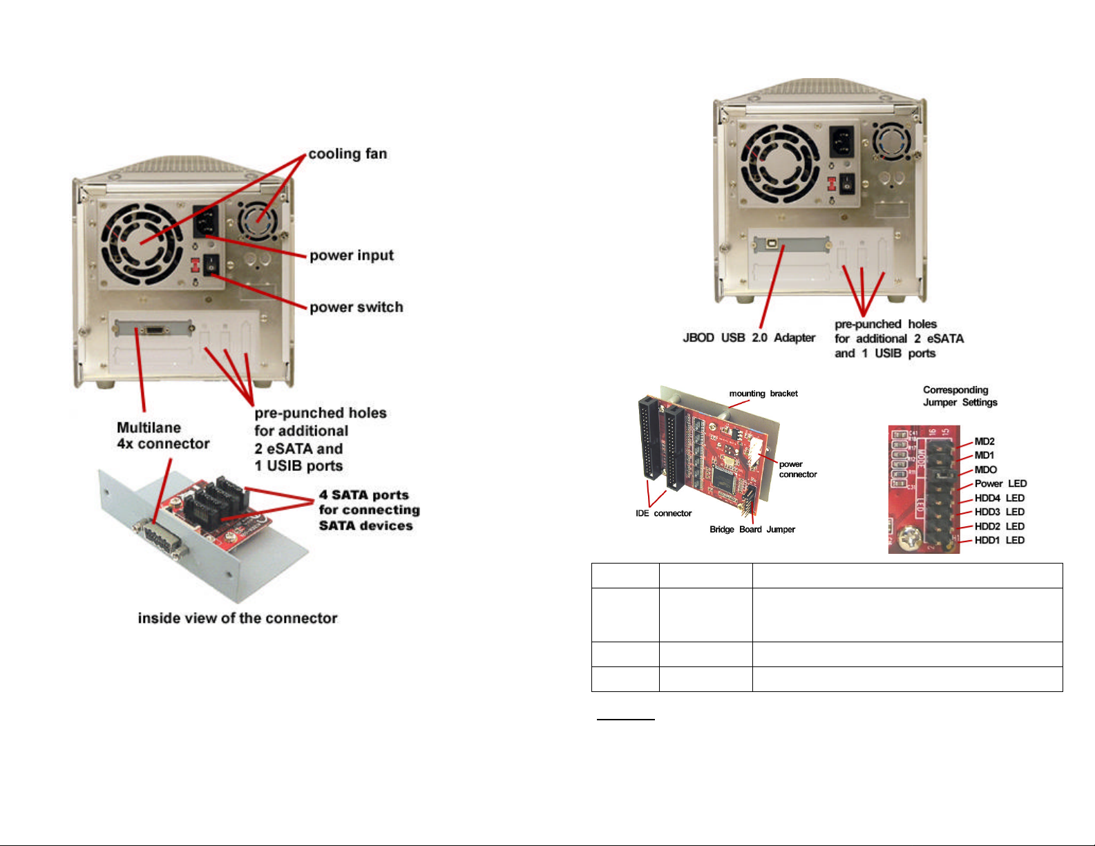
Tower with Multilane Connector
Hot swap feature depends on the SATA controller. All Addonics SATA controllers
support the hot swap feature. Check with your system supplier to confirm the
existing SATA port on your system supports hot swap feature.
Tower with JBOD USB 2.0 Adapter
Note: It is important that you have configured your Multilane Host controller
before connecting it to the tower.
MODE # MODE Description
MD2 2 HDD Mode ON: Combines P1 (two disk drives as one large disk
drive) and combines P3 (two disk drives as another
entire disk drive
MD1 1 HDD Mode ON: Combines 4 disk drives as one large disk drive
MD0 4 HDD Mode ON: Separate 4 hard drives
Important
o IDE drive settings must be set to one MASTER and one SLAVE if two drives
will be connected on a single IDE ribbon.
o Connect the MASTER drive at the end of the cable and the SLAVE drive at
the middle.
Page 8

Technical Support
If you need assistance to get your unit functioning properly, please call Addonics
Technical Support. Our technical staff will be happy to assist you, but they will
need your help to do so. Calling the technical support staff without all the proper
information can be both time consuming and frustrating. Here are some tips to
help you out:
MODEL NUMBER – Please have this number on hand.
SYSTEM INFORMATION – Type of computer, peripherals, etc.
OPERATING SYSTEM – What version of Windows
WHAT’S THE TROUBLE? – Give enough information
about your problem so that we can recreate and diagnose it.
FREE Software Drivers for all Addonics Technologies
Products are available 24 hours per day at the
World Wide Web Site: www.addonics.com.
Contact Information
Phone: 408-433-3899
Fax: 408-433-3898
Email: http://www.addonics.com/sales/query/
Internet: http://www.addonics.com
TECHNICAL SUPPORT
Phone: 408-433-3855
Hours: 8:30 am - 6:00 pm PST
Email: http://www.addonics.com/support/query/
 Loading...