

Page 1
ADDONICS TECHNOLOGIES
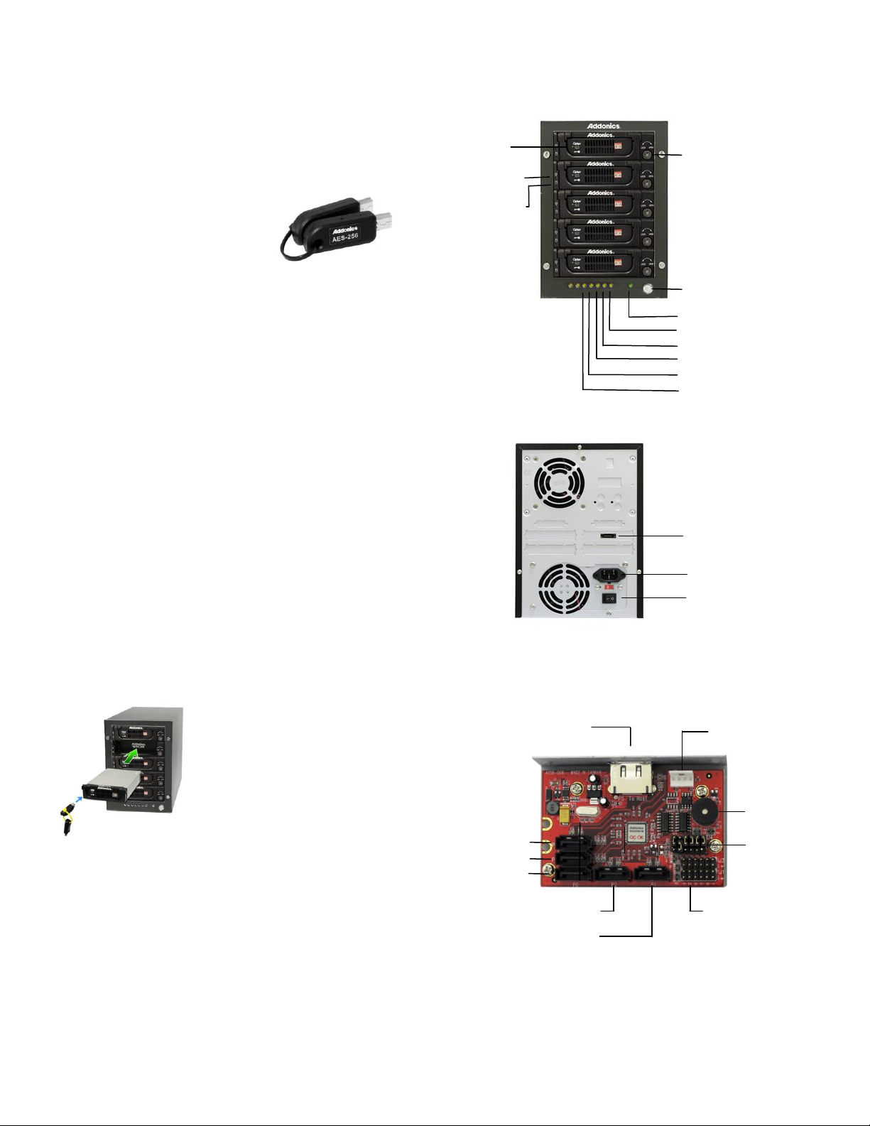
HDD Activity LED 3
HDD Activity LED 2
Cipher tower power LED
Power Switch
HDD Activity LED 1
Power Switch
eSATA port
Power Connector
eSATA host port
buzzer
Floppy power
connector
SATA port 5
SATA port 4
SATA port 1
SATA port 3
SATA port 2
Error and drive activity
LED jumper block (J1, J3)
RAID settting
jumper block (J4)
HDD Activity LED 5
HDD Activity LED 4
Locking
mechanism
Cipher
keyhole
HDD
Power LED
HDD
Activity LED
IMPORTANT
There is no back door for the Cipher tower encrypted hard drives if
the Cipher keys are lost or stolen.
Cipher key
Check to make sure you have the
correct version of the Cipher key. A
sample key is shown
Black label AES-256 stands for Cipher
256-bit key.
To ensure there is a spare key, your Cipher tower comes with 5 pairs of
Cipher keys. These cipher keys have all identical encryption code unless
you requested then to be coded differently. One of these keys should be
kept in a safe and secure location and can be sent back to Addonics for
duplicating additional keys. If you are down to the last key, be sure to
make a back up of all the data stored inside your Cipher tower prior to
sending the last key to Addonics. Addonics is not responsible for key lost
in the mail or retrieval of the data inside the encrypted hard drive.
Keeping track of the hard drive
If you are using the Cipher tower to encrypt multiple hard drives, it is
important to label your hard drive if you are taking the drive out of the
Cipher tower. The hard drive from the Cipher tower that is encrypted will
look like a brand new drive when attach directly to the SATA controller of
a computer. There will be no partition or any hint to indicate that the drive
contains encrypted data. When the drive is partitioned, all the encrypted
data will be lost.
The same holds true if a hard drive already has data on it is installed into
the Cipher tower. The computer detects the hard drive as a brand new
drive or a drive that is unallocated. Once you proceed to partition the
drive, the data that was on the hard drive will be erased and cannot be
recovered.
I. Installing drives into the Cipher Tower
Refer to Diamond Cipher enclosure hard drive installation guide
II. Connecting the power cable and Cipher Tower to the computer
a. Connect the power cord provided from the wall outlet to the back of
the Cipher Tower.
b. A power switch is located on the front of the tower. Make sure the
power is off on the switch (power LED light should be off)
c. Connect the provided eSATA or USB2.0 cable from the back of the
Cipher tower to the eSATA or USB2.0 on the computer. We
recommend connecting the eSATA port for best performance if this
port is available on your computer.
Slide the enclosure into the drive bay.
Using the key provided, insert it to the lock
mechanism and turn it to the “LOCK”
position. This will secure the enclosure and
provide power to the drive.
Note: It is recommended to fill up the tower
with SATA drives from top to bottom. This
is to help in identifying which drives
connects to which ports for easier
troubleshooting.
Model: CDC5HXAES
III. 5-port HPM-XA mounted on the Cipher Tower
Page 2
ADDONICS TECHNOLOGIES
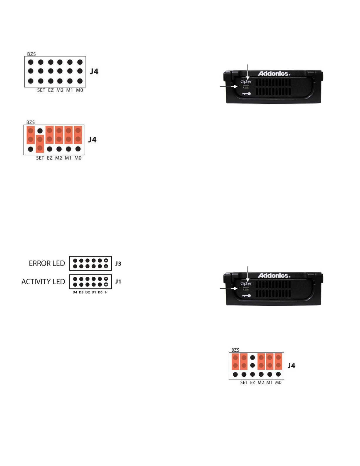
Cipher keyhole
Cipher
power LED
Cipher keyhole
Cipher
power LED
Model: CDC5HXAES
J4 – RAID Setting Jumper Block
BZS – Error buzzer function
SET – RAID mode setting
EZ – Automatic rebuilding to
spare drive
M2 – RAID mode 2
M1 – RAID mode 1
M0 – RAID mode 0
Default factory RAID jumper setting
1. Error buzzer function is DISABLED (BZS)
2. RAID mode setting modification is DISABLED (SET)
3. Auto-rebuilding to spare drive is ENABLED (EZ)
4. Individual drive mode is ENABLED (M0~M2)
Note: When the default factory RAID setting is used, independent drive
configuration and optical drive are supported only when connecting to
controllers with Silicon Image Sil3124, Sil3132 chip set or controllers that
are Port Multiplier (PM) compatible. Simultaneous DVD writing was tested
using the Nero Burning Rom.
LED Pin header
a. Insert the 5 AES 256-bit cipher keys into each cipher keyhole
on the Diamond Cipher enclosures located at the front of the
Cipher tower.
b. When the Cipher Tower power switch is turned on, observed
that the green Cipher power LEDs at the front of the Cipher
tower are on. If they did not, reinsert the cipher keys and re-
power the Cipher tower.
c. Run the JMicron HW RAID Manager in Windows.
d. Configure the desired RAID configuration
e. Go to the operating system’s management utility to verify raid
volume detection.
f. Partition, format and mount the encrypted drives.
B. Using the onboard RAID setting jumper block on the 5-port
HPM-XA
Recommended to be used on operating system without JMicron
HW RAID Manager support like Linux, Mac & Solaris. Windows
users can also use the procedure below.
Note: Steps 1 ~ 4 needs to performed each time the raid mode is
modified.
1. Insert the 5 AES 256-bit cipher keys into each cipher keyhole on the
Diamond Cipher enclosures located at the front of the Cipher tower.
J1 – Drive Activity LED
H – Activity LED for eSATA host port lights up when it is connected to a
SATA controller card.
D0, D1, D2, D3 & D4 - Activity LEDs for port 1, 2, 3, & 4 light up when a
drive is connected and blinks when there’s drive activity.
J3 – Error LED
H – error LED for eSATA host port
D0, D1, D2, D3 & D4 - error LED for port 1, 2, 3 & 4
Two options for setting or modifying the RAID mode on the Cipher
Tower
A. Using the JMicron HW RAID Manager utility program
For Windows users, install the JMicron HW RAID Manager located
on the SATA Controller CD. In the CD, go to RAID utilities >
JMB393. This manager can be use to create and monitor the
status of the RAID volume.
It is recommended to use the default factory RAID jumper setting
when using the JMicron HW RAID Manager.
2. When the Cipher Tower power switch is turned on, observed that
the green Cipher power LEDs at the front of the Cipher tower are on.
If they did not, reinsert the cipher keys and re-power the Cipher
tower.
3. Set the J4 RAID setting jumper block as shown below.
(ignore EZ pins, EZ is DISABLED)
Note: If the JMicron HW RAID Manager is used to create a raid
volume using the RAID mode diagram above the raid metadata will
not be saved. When a reboot of HPM-XA is made, it resets and
deletes all raid metadata.
4. Turn on the Cipher Tower for at least 5 seconds for hardware port
multiplier initialization. This step acts as a reset.
5. Power off the Cipher Tower.
6. On the J4 RAID setting jumper block, change (M0~M2) jumper
setting to the desired RAID mode using the diagram on the next
page as reference.
Page 3

ADDONICS TECHNOLOGIES
Model: CDC5HXAES
All settings on the diagram shows
RAID mode setting modification is ENAABLED (SET)
Error buzzer function is DISABLED (BZS)
7. Power on the Cipher Tower.
8. Verify if the RAID array is detected by the system
a. If the 5-port HPM-XA is connected to the motherboard onboard
SATA, on the CMOS setup utility, the raid array will display as
“Addonics H/W RAID5” if setup as a RAID5 array.
b. If the 5-port HPM-XA is connected to an eSATA host controller
card, on the RAID BIOS, the raid array will display as
“Addonics H/W RAID0” if setup as a RAID0 array.
c. If booted into Windows, in Disk Drives under Device Manager,
the raid array will display as “Addonics H/W LARGE” if setup as
9. Once raid array is verified, you can set back the RAID jumper setting
or the diagram below where buzzer is ENABLED.
a RAID0 array.
back to default
Note: On this setting, there is no jumper on SET.
RAID Setting Notes:
Notes on Spare Drives
Using the Easy RAID Setting (EZ)
In reference to the diagram, the auto-rebuilding to spare drive is
ENABLED (EZ)
When EZ mode is ENABLED, the degraded RAID group will start
rebuilding automatically by using the existing spare drive.
* Spare drive can be either plugged before RAID building or a new drive
can be plug as the spare drive when RAID rebuild is required.
A. Which port acts as a spare drive?
The last drive will automatically become the spare drive.
For a 3-drive RAID5 with spare:
Drives connected to SATA ports 1~3 belong to the active RAID5 array
and drive connected to port 4 is the spare.
For a 4-drive RAID10 with spare:
Drives connected to SATA ports 1~4 belong to the active RAID10 array
and drive connected to port 5 is the spare.
For a 2-drive RAID1 with spare:
Drives connected to SATA ports 1& 4 belong to the active RAID1 array
and drive connected to port 5 is the spare.
B. When will rebuild action start?
When the raid fails and EZ is enabled, the HPM-XA will
automatically rebuild the RAID group using the spare.
When the raid fails and EZ is disabled, the HPM-XA will NOT rebuild the
raid group unless you install a good drive to replace the failed drive.
When 2 drives are connected to the
HPM-XA, and J4 is set to this setting,
the 2 drives will be configured as a
2-drive RAID1 array.
When 4 drives are connected to the
HPM-XA, the 4 drives will be
configured as a 4-drive RAID10 array.
Clone’s action is similar to RAID1.
However, all of the hard drives will be
mirrored. Clone mode is useful
especially when users like to copy
data from a source hard drive to the
drives connected to the HPM-XA.
Page 4

ADDONICS TECHNOLOGIES
Model: CDC5HXAES
III. How to operate the Cipher tower after initial setup
1. Insert the 5 AES 256-bit cipher keys into each cipher keyhole on the
Diamond Cipher enclosures located at the front of the Cipher tower.
2. Push the power switch of the Cipher tower to turn it on. Observed
that the green Cipher power LEDs at the front of the Cipher tower
are on. If they did not, reinsert the cipher keys and re-power the
Cipher tower.
3. Use the system’s File Explorer to access the files on the encrypted
drive.
4. For security purposes, remove the cipher keys from the Cipher
tower after the drives are detected by the system. All the files being
transferred into the drives are still encrypted even if the cipher key is
removed.
5. When the Cipher tower is restarted, the 4 cipher keys must be
inserted again in order to gain access to the drives.
Best Practice:
Create a label to identify the SATA hard drive and the associated Cipher
key used.
TECHNICAL SUPPORT
Phone: 408-453-6212
Hours: 8:30 am - 6:00 pm PST
Email: http://www.addonics.com/support/query/
 Loading...