

Page 1

Addonics
T E C H N O L O G I E S
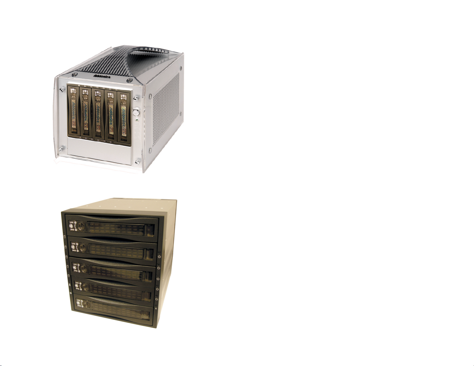
3-to-5 SA Disk Array
Enclosure
(AE5RCS35NSA, AE5RCS35NSAW)
User’s Guide
Version 1.0
Page 2

FCC Warning Statement
This equipment has been tested and found to comply with the limits for a class
B digital device pursuant to Part 15 of the FCC rules. These limits are
designed to provide reasonable protection against harmful interference in a
residential installation. Th is equipment generates, uses and can radiate radio
frequency energy. If not installed and use d in accordance with the instructions,
it may cause harmful interference to radio communications. However, there is
no guarantee that interference will not occur in a particular in stallation. If the
equipment does cause harmful interference to radio or television reception,
which can be determined by turning the equipment on and off, the user is
encouraged to try and correct the interference by one or more of the following
suggestions.
• Reorient or relocate the receiving antenna
• Increase the distance between the equipment and the receiver
• Connect the equipment to a different power outlet other than the
one where receiver is connected
• Consult a certified television or radio technician
LIMITED WARRANTY
Addonics guarantees that every product is free from physical defects in material
and workmanship dur ing the warranty period specified for each product when
used within the limits set forth in the Specifications section in the user guide.
Unauthorized tampering of the product or using it outside the scope of the
product specifications will result in voiding the warrant y. If the product proves
defective during th is warranty period, call Addonics Technical Support to
obtain a Return Authorization number. BE SURE TO HAVE YOUR PROOF
OF PURCHASE ON HAND WHEN CALLING. RETURN REQUESTS
CANNOT BE PROCESSED WITHOUT PROOF OF PURCHASE. When
returnin g a product, mark the Return Authorization number clearly on the
outside of the package and include your original proof of purchase. Customers
are responsible for paying th e shipp ing and handling of the products to
Addonics warran ty service location.
IN NO EVENT SHALL ADDONICS’ LIABILITY EXCEED THE PRICE
PAID FOR THE PRODUCT FROM DIRECT, INDIRECT, SPECIAL,
INCIDENTAL, OR CONSEQUENTIAL DAMAGES RESULTING FROM
THE USE OF THE PRODUCT, ITS ACCOMPANYING SOFTWARE, OR
ITS DOCUMENTATION. Addonics makes no warranty or representation,
expressed, implied, or statuary, with respect to its products or the contents or
use of the user guide and all accompanying software, and specifically disclaims
its quality, performance, merchantability, or fitness for any particular purpose.
Addonics reserves the right to revise or update its products, software, or
documentation without obligation to notify any individual or entity.
Addonics Technologies – 3-to-5 SA Disk Array User’s Guide v1.0 1
Page 3

Contents
FCC Warning...................................................................................1
Limited Warranty............................................................................ 1
Contents............................................................................................ 2
Chapter 1 General Information .........................................................3
Features................................ ............................................3
Chapter 2 Disk Array Parts & Functions ...........................................4
Chapter 3 Caddy Drive Drawer Install ..............................................8
Chapter 4 Product Application..........................................................9
Technical Support & Contact Information................................ …10
Addonics Technologies – 3-to-5 SA Disk Array User’s Guide v1.0 2
Page 4

Chapter 1
General Information
The Addonics 3-to-5 Disk Array system makes implementing sophisticated
RAID technology into any computer simple. Designed to accommodate up to
five 3.5" SATA or SATA II hard drives into three 5 ¼” drive bay, each hard
drive can be easily secured inside or removed from the Disk Array rack with
the simple aluminum drive drawer.
Features
• Disk Array 5SA - for installing 5 SATA hard drives into three 5 1/4" drive
bay stack
• Can be used as an external RAID system using optional external power
adapters(See power supply requirement below)
• High throughput up to 150 MB/sec with SATA and 300 MB/sec with
SATA II
• Full Serial ATA 1.0 and 2.0 compliant
• Aluminum frame and drive drawer
• Choice of black color bezel or ivory color bezel
• Innovative lock and handle for each drive drawer
• Drive drawer can be interchan ged with the ABS plastic version of the
Drive Cartridge System SA35.
• Use as an external RAID system (require optional external power adapter)
• Hot swap (1) support
• Point to point connection, no cabling needed to install the hard drive into
the drive drawer
• SATA 15 pin and standard 4 pin PC power connector
• Power switch/LED indicator an d over temperature buzzer alarm
• Fan switch/LED indicator and failure buzzer alarm
• Power switch/LED for each hard drive
• Drive can be removed and used as an external Serial hard drive on other
computers with an optional Serial ATA power adapter.
Addonics Technologies – 3-to-5 SA Disk Array User’s Guide v1.0 3
Page 5

Chapter 2 Disk Array Parts and Functions
D2 D3 D4 D5 D6 D7 D8 D9
Front Panel
HD1
HD2
D10
HD3
D11
D12
HD4
D13
HD5
D14
D1 – D5: HD1 – HD5 power switch
D6: Reset Switch for buzzer alarm and Overheating
Press the Reset Switch to stop the alarm, and Overheating LED
goes off.
D7 – D11: Power and HDD access LED
LED light is GREEN when power is ON. LED light is blinking and
its color is ORANGE indicating HDD access.
D1
Addonics Technologies – 3-to-5 SA Disk Array User’s Guide v1.0 4
Page 6

POWER SWITCH
Each individual hard drive on the disk array has its own power switch.
TURNING ON a Hard Drive
To turn on a hard drive, using a pointed
object insert it on the circular slot (D1 –
D5) located on top of the power logo and
push it. The power and HDD access LED
(D7 – D11) would light up (green color).
TURNING OFF a Hard Drive
To turn off a hard drive, using a pointed
object insert it on the circular slot (D1 –
D5) located on top of the power logo and
push it. The power and HDD access LED
(D7 – D11) goes off.
D12: Overheating LED
When overheating occurs, the buzzer alarms (default setting: 60 0C
and the Temperature LED turns red while buzzer is alarming
and LED is blinking).
D13: Fan Sensor LED
LED light is Green when it is working. When the fan fails, LED
light turns Red.
D14: Safety Lock
The safety lock safeguards the hard disk in the correct position and
prevents it from being ejected out while HDD is working.
Addonics Technologies – 3-to-5 SA Disk Array User’s Guide v1.0 5
Page 7

Rear View
Power 2
HD1
HD2
HD3
Power 1
J5
HD4
HD5
POWER1: 4-pin Molex Power connector
Note: One 4-pin Molex power connector powers 2 drives. In order t o power
all 5 drives all three 4-pin connectors must be connected
POWER2: 15-pin Serial ATA Data Power connector
Note: The top 15-pin Serial ATA Data Power connector powers 2 drives.
The second 15-pin Serial ATA Data Power connector powers the three
bottom drives.
HD1—HD5: 7-pin Serial ATA Signal connector
If your power is not from SATA 15pin connector, then, use the 4pin power
connector, the 4pin power will automatically be convert to SATA power.
J5: FAN RPM HIGH (3600 rpm) & LOW (2800 rpm) Options
Addonics Technologies – 3-to-5 SA Disk Array User’s Guide v1.0 6
Page 8

lJP1: Temperature setting jumper
lJP2 & J4: Extension function jumper
FLR: Fan failure detection (red)
FL+: Fan failure detection (+)
FLG: Fan failure detection (green)
RST: Reset Switch for buzzer alarm and Overheating LED
TLR: Temperature detection (red)
5V+: 5V Power
TLG: Temperature detection (green)
GND: Grounded
PL1- • PL5-: Ext Power LED detection (-)
HL1- • HL5-: Ext HDD LED detection (-)
VCC1- • VCC5-: Ext 5V Power (+)
Addonics Technologies – 3-to-5 SA Disk Array User’s Guide v1.0 7
Page 9

Chapter 3 Caddy Drive Drawer Install
Using the screws provided, secure the hard drive to the drive drawer.
Addonics Technologies – 3-to-5 SA Disk Array User’s Guide v1.0 8
Page 10
Chapter 4 Product Application
5SA Disk Array Mounted on a Storage Tower
5SA Disk Array as a Standalone
Addonics Technologies – 3-to-5 SA Disk Array User’s Guide v1.0 9
Page 11

Technical Support
If you need assistance to get your unit functioning properly, please call
Addonics Technical Support. Our technical staff will be happy to assist you,
but they will need your help to do so. Calling the techni cal support staff
without all the proper information can be both time consuming and frustrating.
Here are some tips to hel p you out:
(1) MODEL NUMBER – Please have this number on hand.
(2) SYSTEM INFORMATION – Type of computer, peripherals, etc.
(3) OPERATING SYSTEM – What version of Windows
(4) WHAT’S THE TROUBLE? – Give enough information
About your problem so that we can recreate and diagnose it.
FREE Software Drivers for all Addonics Technologies
Products are available 24 hours per day at the
World Wide Web Site: www.addonics.com.
Contact Information
Addonics Technologies
2466 Kruse Drive
San Jose CA, 95131
Phone: 408-433-3899
Fax: 408-433-3898
Email: sales-team@addonics.com
Internet: http://www.addonics.com
TECHNICAL SUPPORT
Phone: 408-433-3855
Hours: 9:00-6:00 PST
Email: techinfo@addonics.com
Addonics Technologies – 3-to-5 SA Disk Array User’s Guide v1.0 10
 Loading...