

Page 1
CON1
CON2
CON4
CON3
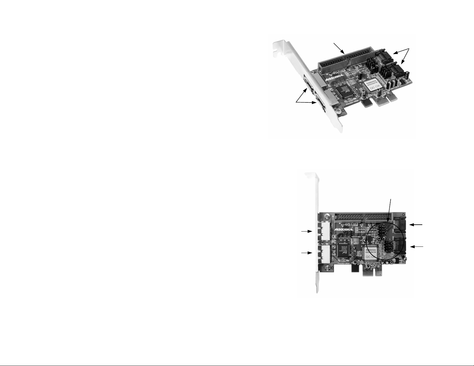
Overview
IDE Channel
Internal
SATA ports
Addonics
T E C H N O L O G I E S
SATA/IDE RAID PCI-E Controller
Model: ADI2S3GPX1-2E
User’s Guide
Note: The IDE devices attach to the IDE channel must be set as a master and
eSATA
Ports
slave pair.
Jumper Pins
Version 1.0
FCC Warning Statement
This equipment has been tested and found to comply with the limits for a class B digital
device pursuant to Part 15 of the FCC rules. These limits are designed to provide
reasonable protection against harmful interference in a residential installation. This
equipment generates, uses and can radiate radio frequency energy. If not installed and
used in accordance with the instructions, it may cause harmful interference to radio
communications. However, there is no guarantee that interference will not occur in a
particular installation. If the equipment does cause harmful interference to radio or
television reception, which can be determined by turning the equipment on and off, the user
is encouraged to try and correct the interference by one or more of the following
suggestions.
Reorient or relocate the receiving antenna
Increase the distance between the equipment and the receiver
Connect the equipment to a different power outlet other than the one where receiver is
connected
Consult a certified television or radio technician
Note: There are four SATA ports in SATA/IDE RAID PCI-E controller card.
These ports are named CON1 to CON4. Ports CON3 & CON4 are
eSATA ports and CON1 & CON2 are internal SATA ports. Changing the
jumper setting on the SATA/IDE RAID PCI-E Controller card allows
you to select between eSATA and internal SATA ports. By default, ports
CON1 & CON2 are enabled.
Page 2
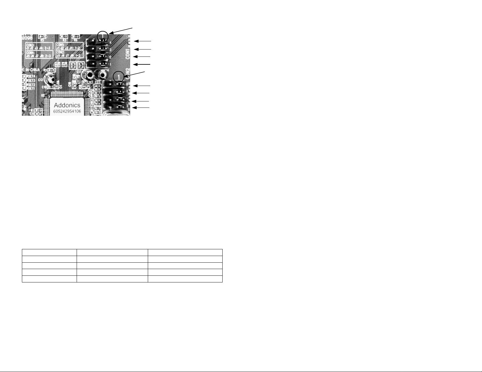
Detailed View of Jumper Pins
Pin 1 Pin 1 J4 J3
J2 J1
J8 J7 J6
J5
To enable CON3 and disable CON1,
transfer jumper to pins 2 & 3 on J1, J2, J3 & J4
To enable CON4 and disable CON2,
transfer jumper to pins 2 & 3 on J5, J6, J7 & J8
Recommendations on using the ADI2S3GPX1-2E
There are two ways of configuring raid sets on the ADI2S3GPX1-2E. Use the
RAID BIOS of the controller card which shows up after POST or install the
JMB36X RAID Configurer in Windows to create raid volumes. The JMB36X RAID
Configurer will not run when no devices are attached to the controller.
Using the RAID BIOS to create RAID Volumes
There are four configurations supported:
RAID level/Type Configurations Number of disks needed
RAID 0 Disk Striping 2 or 3 or 4
RAID 1 Disk Mirroring 2
RAID 0+1 Disk Striping + Mirroring 4
JBOD Disk Concatenation 2 or 3 or 4
RAID 0 (Striping)
1. Press Ctrl+J when prompted to enter the RAID BIOS.
2. At the next screen select Create RAID Disk Drive , press Enter.
3. Enter RAID name, press Enter.
4. Use arrow keys • and •to switch the RAID level to 0-Stripe, then press
Enter.
5. Use arrow keys • and •to switch the disk, use the “space” key to mark the
selected disk, then press Enter.
6. Use arrow keys • and • to select chunk size from 4K, 8K, 16K, 32K, 64K
or 128K, then press Enter.
7. Input the RAID size, press Enter.
8. When asked Create RAID on the select HDD (Y/N)?, press Y to accept.
9. At the next screen select Save And Exit Setup, press Enter.
10. When asked Save to disk &Exit (Y/N)?, press Y to exit the RAID BIOS.
RAID 1 (Mirroring)
1. Press Ctrl+J when prompted to enter the RAID BIOS.
2. At the next screen select Create RAID Disk Drive , press Enter.
3. Enter RAID name, press Enter.
4. Use arrow keys • and •to switch the RAID level to 1-Mirror, then press
Enter.
5. Use arrow keys • and •to switch the disk, use the “space” key to mark the
selected disk, then press Enter.
6. Input the RAID size, press Enter.
7. When asked Create RAID on the select HDD (Y/N)?, press Y to accept.
8. At the next screen select Save And Exit Setup, press Enter.
9. When asked Save to disk &Exit (Y/N)?, press Y to exit the BIOS.
CONCATENATION (JBOD)
1. Press Ctrl+J when prompted to enter the RAID BIOS.
2. At the next screen select Create RAID Disk Drive, press Enter.
3. Enter RAID name, press Enter.
4. Use arrow keys • and •to switch the RAID level to JBOD-Concatenate,
then press Enter.
5. Use arrow keys • and •to switch the disk, use the “space” key to mark the
selected disk, then press Enter.
6. Input the RAID size, press Enter.
7. When asked Create RAID on the select HDD (Y/N)?, press Y to accept.
8. At the next screen select Save And Exit Setup, press Enter.
9. When asked Save to disk &Exit (Y/N)?, press Y to exit the BIOS.
RAID 0+1 (Striping + Mirroring)
1. Press Ctrl+J when prompted to enter the RAID BIOS.
2. At the next screen select Create RAID Disk Drive, press Enter.
3. Enter RAID name, press Enter.
4. Use arrow keys • and •to switch the RAID level to 01-Stripe+Mirror, then
press Enter.
5. Use arrow keys • and • to select chunk size from 4K, 8K, 16K, 32K, 64K
or 128K, then press Enter.
6. Input the RAID size, press Enter.
7. When asked Create RAID on the select HDD (Y/N)?, press Y to accept.
8. At the next screen select Save And Exit Setup, press Enter.
9. When asked Save to disk &Exit (Y/N)?, press Y to exit the BIOS.
Page 3

Delete RAID Disk Drive
1. Press Ctrl+J when prompted to enter the RAID BIOS.
2. At the next screen select Delete RAID Disk Drive, press Enter.
3. Use arrow keys • and •to select the array you want to delete, use the
“space” key to mark the selected array, then press DEL.
4. When asked ALL DATA ON THE RAID WILL LOST!! ARE YOU SURE TO
DELETE (Y/N), press Y to accept.
Solve Mirror Conflict
When a RAID set is created, metadata which includes drive connection
information is written to the disk. If after a disk failure, the drive that failed was
replaced by a disk that was previously part of a RAID set (or used in another
system), it m ay have conflicting metadata. This will prohibit the RAID set from
being either created or rebuilt. In order for the RAID set to function properly, this
old metadata must be first overwritten with new metadata. To resolve this, from
the main RAID BIOS window select Solve Mirror Conflict, then press Enter, the
correct metadata, including the correct drive connection information, will be
written to the replacement disk.
Rebuild Mirror Drive
If a failure on one member occurs, you will be notified by the
RAID BIOS during boot. The steps below will guide you in rebuilding
a failed mirror set.
1. Replace the failed drive with one of equal or greater capacity, then start the
computer.
2. During boot press Ctrl+J to enter the RAID BIOS.
3. Select Rebuild Mirror Drive press Enter.
4. Use arrow keys • and •to select the array you want to rebuild, press
Enter.
5. Use arrow keys • and •to select the destination disk, press Enter.
6. When rebuilding is finished, select Save And Exit Setup, press Enter.
When asked Save to disk &Exit (Y/N)?, press Y to exit the BIOS.
Steps:
1. JMB36X RAID Configurer installation
Note: To create raid volumes and monitor the status of your raid set, you need
to install t he JMB36X RAID Configurer. Install the utility from the CD
that came with your package.
a. Turn computer ON. Insert Host Controller Driver Disk into CDROM.
b. The Addonics Technologies Driver Disk window pops up.
c. Select Other Controllers. Click the ADI2S3GPX1-2E. Extract the files
into your system.
d. Install JMB36X RAID Configurer by clicking the Setup.exe. Follow the
instructions.
e. After software installation, reboot the system.
2. To open the JMB36X RAID Configurer, click on the system tray the JMicron
Icon.
3. This will open up the JMB36X RAID Configurer.
Create
RAID
Create
RAID from
Existing Disk
Show Disk
Rebuild
RAID
Remove
RAID
Page 4

Driver Installation For A New Fresh Windows Install
A new installation requires a floppy disk for the driver
installation. To make this floppy disk, copy the contents of
the “Drivers\JMB36X\WIN2K_XP_2003_VISTA\Floppy32” folder, found on the
driver CD, onto a blank floppy disk then follow the directions below.
1. Setup the RAID Array prior to Windows installation.
2. Follow Microsoft’s Windows installation procedure.
3. Restart the computer when prompted by Windows’ installation.
For Windows® 2000, XP and Server 2003
4. At the Windows Setup screen, press F6 to install the RAID driver.
5. When prompted, press S to specify the location of the driver.
6. Insert the floppy disk, then press Enter.
7. Select (Windows 2000) RAID Driver for JMicron JMB363 Controller or
(Windows XP/2003) RAID/AHCI Driver for JMicron JMB36X Controller,
then press Enter.
8. Press Enter to finish driver installation, then follow the on-screen instructions
to complete the Windows installation.
For Windows® Vista
4. At the Windows Setup screen, press Load Driver to install the driver.
5. Insert the floppy disk, please select JMicron JMB36X Controller
(A:\jraid_f.inf), then press Next. (Change A:\ to match your floppy drive
letter)
6. Follow the on-screen instructions to complete the Windows installation.
For Windows® XP-x64/Server 2003-x64
4. At the Windows Setup screen, press F6 to install the driver.
5. When prompted, press S to specify the location of the driver.
6. Insert the floppy disk, then press Enter.
7. Select (Windows XP/2003 x64) RAID/AHCI Driver for JMicron JMB36X
Controller, then press Enter.
8. Press Enter to finish driver installation, then follow the on-screen instructions
to complete the Windows installation.
To Verify Driver Installation
1. Right click My Computer and click Manage.
2. Select Device Manager.
3. Look for the following:
Windows® 2000/XP/2003: Double click SCSI and RAID Controller:
-JMicron JMB36X Controller should be displayed
Windows® Vista: Double click Storage controllers:
-JMicron JMB36X Controller should be displayed
Technical Support
If you need assistance to get your unit functioning properly, please call Addonics
Technical Support. Our technical staff will be happy to assist you, but they will
need your help to do so. Calling the technical support staff without all the proper
information can be both time consuming and frustrating. Here are some tips to
help you out:
MODEL NUMBER – Please have this number on hand.
SYSTEM INFORMATION – Type of computer, peripherals, etc.
OPERATING SYSTEM – What version of Windows
WHAT’S THE TROUBLE? – Give enough information
about your problem so that we can recreate and diagnose it.
FREE Software Drivers for all Addonics Technologies
Products are available 24 hours per day at the
World Wide Web Site: www.addonics.com.
Contact Information
Phone: 408-573-8580
Fax: 408-573-8588
Email: http://www.addonics.com/sales/query/
Internet: http://www.addonics.com
TECHNICAL SUPPORT
Phone: 408-453-6212
Hours: 8:30 am - 6:00 pm PST
Email: http://www.addonics.com/support/query/
 Loading...