

Page 1
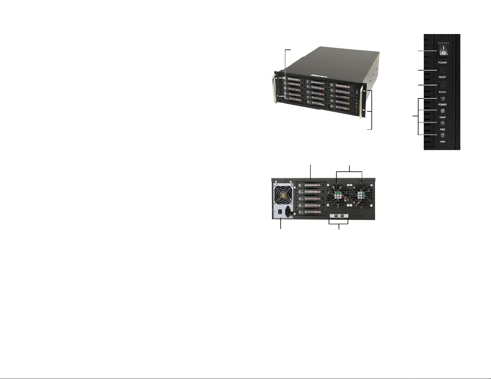
RAID Rack Overview
Mounting Holes
Power Switch
Top Cover
S
ystem Reset
Addonics
TECHNOLOGIES
RAID Rack
RR2035RPHES, RR2035AXHES,
RR2035RPHML, RR2035AXHML
User’s Guide
TECHNICAL SUPPORT
Phone: 408-453-6212
Hours: 8:30 am - 6:00 pm PST
Email: http://www.addonics.com/support/query/
Buzzer Reset
LED Display
Power Switch: This is the switch to power on devices connected to the power supply. The
power LED will light up to indicate power is supplied.
Note: The main power switch located at the back of the enclosure must be turned on first.
Reset Button: Not operational.
Buzzer Reset: Pressing the button stops the buzzer from making a sound. The buzzer will
make a sound when temperature inside the storage rack exceeds the temperature setting
on the Thermal Management card.
Power LED: Lights up when the power switch is turned on.
Temp LED: Lights up when temperature setting inside the storage rack exceeds the setting
on the thermal card.
Fan LED: Normally on when fan is operational. If an abnormal condition is detected, the
LED flashes.
4th 5SA disk array
Power
Supply
Mounting Holes
Fans
4 eSATA ports
Page 2
HDD LED: Not operational.
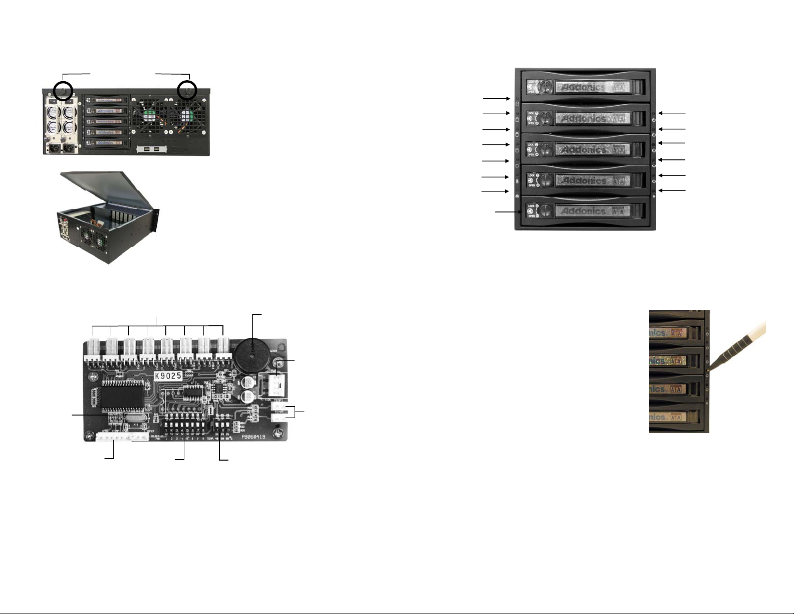
How to remove the top cover:
Screw
locations
Locate the 2 screws at the back
1.
of the storage rack
2. Turn screws counterclockwise to
loosen
.
Lift the top cover and pull towards the rear end
3.
of the rack.
Thermal Management Card on the RAID Rack
Fan Connectors
Overheat Buzzer
Floppy Power
Connector
Reset Switch
Connector
Ambient Detect
Terminal
Fan, temperature and
power LED connectors
Fan detect
Selection
Temp. Setting
o
C, 50oC, 60oC)
(40
F
eatures:
Fan1 to Fan8 could be set either “ENABLE” or “DISABLE”. When all the fans are set on
“DISABLE”, the Fan LED will have no light on.
When Ambient temperature (or temperature inside the storage rack) is over the set
temperature, the LED will flash and the buzzer will sound.
5SA Disk Array mounted on the RAID Rack
D7
D8
D9
D10
D11
D12
D13
HD1
HD2
HD3
HD4
D1
D2
D3
D4
D5
D6
D14
HD5
D1 – D5: HD1 – HD5 power switch
D6: Reset Switch for buzzer alarm and Overheating
D7 – D11: Power and HDD access LED
LED light is GREEN when power is ON. LED light is blinking and its color is ORANGE
indicating HDD access.
POWER SWITCH
Each individual hard drive on the disk array has its own
power switch.
TURNING ON a Hard Drive
To turn on a hard drive, using a pointed object insert it on
the circular slot (D1 – D5) located on top of the power logo
and push it. The power and HDD access LED (D7 – D11)
would light up (green color).
TURNING OFF a Hard Drive
To turn off a hard drive, using a pointed object insert it on
the circular slot (D1 – D5) located on top of the power logo
and push it. The power and HDD access LED (D7 – D11)
goes off.
Press the Reset Switch to stop the alarm, and Overheating LED goes off.
HD5
Page 3

Hardware Port Multiplier mounted inside the RAID Rack
Floppy
power
SATA host port
SATA por
SATA por
SATA por
t 5
t 4
t 1
SATA por
SATA por
t 3
t 2
J4 – RAID Setting Jumper Block
BZS – Error buzzer function
SET – RAID mode setting
EZ – Automatic rebuilding to spare drive
M2 – RAID mode 2
M1 – RAID mode 1
M0 – RAID mode 0
Default factory RAID jumper setting
1. Error buzzer function is DISABLED (BZS)
2. RAID mode setting modification is DISABLED
(SET)
3. Auto-rebuilding to spare drive is ENABLED
(EZ)
4. Individual drive mode is ENABLED (M0~M2)
Note: When the default factory RAID setting is used, independent drive configuration
is sup
ported only when connecting to controllers with Silicon Image Sil3124, Sil3132
chip set or controllers that are Port Multiplier (PM) compatible.
LED Pin header
connector
buzzer
RAID setting
jumper block (J4)
nd drive activity
Error a
LED jumper block (J1, J3)
J1 – Drive Activity LED
H – Activity
LED for eSATA host port lights up when it is connected to a SATA controller
card.
D0, D1, D2, D3 & D4 - Activity LEDs for port 1, 2, 3, & 4 light up when a drive is connected
and blinks when there’s drive activity.
J3 – Error LED
H – err
or LED for eSATA host port
D0, D1, D2, D3 & D4 - error LED for port 1, 2, 3 & 4
Two Options for Setting RAID on the 5-port HPM-XA
(only select one option)
I. Using the JMicron HW RAID Manager utility program
For Windo
Controller CD. In the CD, go to RAID utilities > JMB393. This manager can be use to
create and monitor the status of the RAID volume.
Use th
Manager.
II.
Using the onboard RAID setting jumper block
(Complete the 7 steps below)
Recommended t
support like Linux, Mac & Solaris. Windows users can also used the procedure below.
1. Set the J4 RAID setting jumper block as shown below.
(ignore EZ pins, EZ is DISABLED)
2.
Turn on the system power where the HPM is connected for at least 5 seconds for
hardware initialization. This step acts as a reset.
3. Power off the system power.
4. On the J4 RAID setting jumper block, change (M0~M2) jumper setting to the desired
RAID mode using the diagram on the next page as reference.
All settings on the diagram shows
RAID mode setting modification is ENAABLED (SET)
Error buzzer function is DISABLED (BZS)
ws users, install the JMicron HW RAID Manager located on the SATA
e default factory RAID jumper setting when using the JMicron HW RAID
o be used on operating system without JMicron HW RAID Manager
Page 4

B. Or to the diagram below where buzzer is ENABLED.
Note: Steps 1 ~ 4 needs to performed each time the raid mode is modified.
5. Power on the system power.
6. Verify if the RAID array is detected by the system
a. If the 5-port HPM-XA is connected to the motherboard onboard SATA, on the
CMOS setup utility, the raid array will display as “Addonics H/W RAID5” if setup
as a RAID5 array.
b. If the 5-port HPM-XA is connected to an eSATA host controller card, on the RAID
BIOS, the raid array will display as “Addonics H/W RAID0” if setup as a RAID0
array.
c. If booted into Windows, in Disk Drives under Device Manager, the raid array will
display as “Addonics H/W LARGE” if setup as a RAID0 array.
7. Once raid array is verified, turn off the system then you MUST set back the RAID
jumper setting to either:
A. Default setting
Note: On the setting where buzzer is ENABLED, there is NO jumper on SET.
RAID Setting Notes:
Notes on R
(Diagram shows default factory RAID jumper setting)
Cable Connections
For Model: RR2035RPHES & RR2035AXHES
1.
For Model: RR2035RPHML, RR2035AXHML
1.
AID Auto rebuild
Connect one end of the eSATA cable to the eSATA port on the RAID Rack and the
other end to the eSATA port on your system.
Attach one end of the infiniband cable to the multilane port on the RAID Rack and the
other end to the multilane port on your system.
When 2 drives are connected to the HPM-XA, and J4 is
set to this setting, the 2 drives will be configured as a
2-drive RAID1 array.
When 4 drives are connected to the HPM-XA, the 4
drives will be configured as a 4-drive RAID10 array.
Clone’s action is similar to RAID1. However, all of the
hard drives will be mirrored. Clone mode is useful
especially when users like to copy data from a source
hard drive to the drives connected to the HPM-XA.
In reference to the diagram, auto-rebuilding is
ENABLED (EZ)
When EZ mode is ENABLED, the degraded RAID
group will start rebuilding automatically when you
install a good drive to replace the failed drive.
 Loading...