

Addon NWAR3650 User Manual

NWAR3650
User Manual

Contents
1 Introduction ........................................................................................................1
1.1 Application ............................................................................................. 1
1.2 Environment Requirements ................................................................... 1
1.3 System Requirements ...........................................................................2
1.4 Safety Cautions .....................................................................................2
1.5 LED Status Description.......................................................................... 2
1.5.1 Front Panel ................................................................................. 2
1.5.2 Rear panel .................................................................................. 4
2 Hardware Installation .........................................................................................4
2.1 Choosing the Best Location for Wireless Operation.............................. 4
2.2 Connecting the ADSL Router ................................................................5
3 Introduction to Web Configuration...................................................................... 7
3.1 Logging In to the Modem....................................................................... 7
3.1.1 First-Time Login.......................................................................... 7
3.2 DSL Router Device Information............................................................. 8
3.2.1 Summary of Device Information .................................................9
3.2.2 WAN Interface Information .........................................................9
3.2.3 Statistics....................................................................................10
3.2.4 Statistics of LAN........................................................................10
3.2.5 Statistics of WAN ...................................................................... 10
3.2.6 Statistics of xTM........................................................................ 11
3.2.7 Statistics of xDSL...................................................................... 11
3.2.8 Route Table Information............................................................ 13
3.2.9 ARP Table Information .............................................................. 13
3.2.10 DHCP IP Lease Information ................................................ 13
3.3 Advanced Setup ..................................................................................14
3.3.1 WAN Configuration ................................................................... 15
3.3.2 LAN Configuration ....................................................................38
3.3.3 NAT........................................................................................... 41
3.3.4 Security..................................................................................... 47
3.3.5 Quality of Service...................................................................... 55
3.3.6 Routing .....................................................................................60
3.3.7 DNS .......................................................................................... 62
3.3.8 DSL........................................................................................... 63

3.3.9 UPNP........................................................................................ 65
3.3.10 DNS Proxy........................................................................... 66
3.3.11 Interface Grouping............................................................... 66
3.3.12 LAN Ports ............................................................................ 70
3.3.13 IPsec ...................................................................................71
3.3.14 Certificate ............................................................................ 74
3.3.15 FTP Configuration ............................................................... 79
3.4 Wireless............................................................................................... 80
3.4.1 Wireless LAN Basics ................................................................80
3.4.2 Wireless – Basic ....................................................................... 80
3.4.3 Wireless – Security................................................................... 82
3.4.4 Wireless-MAC Filter.................................................................. 90
3.4.5 Wireless – Bridge...................................................................... 91
3.4.6 Wireless – Advanced................................................................ 92
3.4.7 Wireless -- Authenticated Stations ............................................ 95
3.5 Diagnostics .......................................................................................... 95
3.6 Management........................................................................................ 96
3.6.1 Settings..................................................................................... 96
3.6.2 System Log............................................................................... 97
3.6.3 TR-069 Client Management ................................................... 101
3.6.4 Internet Time........................................................................... 102
3.6.5 Access Control........................................................................ 103
3.6.6 Update Software ..................................................................... 104
3.6.7 Reboot .................................................................................... 105
4 Q&A................................................................................................................ 106

1 Introduction
The NWAR3650 is a highly ADSL2+ Integrated Access Device. The NWAR3650
can support ADSL link with downstream up to 24 Mbps and upstream up to 1 Mbps.
It is designed to provide a simple and cost-effective ADSL Internet connection for a
private Ethernet. And the wireless access supports IEEE 802.11b, IEEE 802.11g,
and IEEE 802.11n. The Router combines high-speed ADSL Internet connection, IP
routing for the LAN and wireless connectivity in one package. It is usually preferred
to provide high access performance applications for the individual users, the
SOHOs, and the small enterprises.
Network and Router management is done through the Web-based management
interface that can be accessed through the local Ethernet using any web browser.
You may also enable remote management to enable configuration of the Router via
the WAN interface.
1.1 Application
Home gateway
SOHOs
Small enterprises
Higher data rate broadband sharing
Shared broadband internet access
Audio and video streaming and transfer
PC file and application sharing
Wireless access
1.2 Environment Requirements
Operating temperature: 0ºC~40ºC (32ºF to 104ºF)
Storage temperature: -10ºC~55ºC (14ºF to 131ºF)
Operating humidity: 10%~95%, non-condensing
Storage humidity: 5%~95%, non-condensing
Power adapter input: 100V~240V AC, 50/60Hz
Power adapter output: 12V DC, 1A
1

1.3 System Requirements
Recommended system requirements are as follows:
Pentium 233 MHZ or above
Memory: 64 Mbps or above
10M Base-T Ethernet or above
Windows 9x, Windows 2000, Windows XP, Windows ME, Windows NT
Ethernet network interface card
1.4 Safety Cautions
Follow the announcements below to protect the device from risks and damage
caused by fire and electric power.
Use volume labels to mark the type of power.
Use the power adapter that is packed within the device package.
Pay attention to the power load of the outlet or prolonged lines. An
overburden power outlet or damaged lines and plugs may cause electric
shock or fire accident. Check the power cords regularly. If you find any
damage, replace it at once.
Proper space left for heat radiation is necessary to avoid any damage
caused by overheating to the device. The holes are designed for heat
radiation to ensure that the device works normally. Do not cover these heat
radiant holes.
Do not put this device close to a place where a heat source exits or high
temperature occurs. Avoid the device from direct sunshine.
Do not put this device close to a place where is over damp or watery. Do not
spill any fluid on this device.
Do not connect this device to any PC or electronic product, unless our
customer engineer or your broadband provider instructs you to do this,
because any wrong connection may cause any power or fire risk.
Do not place this device on an unstable surface or support.
1.5 LED Status Description
1.5.1 Front Panel
2

Indicator Color Status Description
Off The power is off.
Green
Power
ADSL Green
Internet
LAN4/3/2/1 Green
WLAN Green
WPS Green
USB Green
On
On The power is self-testing.
Red
Blinks Upgrading software.
Off No signal is detected.
Quick Blinks The DSL line is training.
Slow Blinks
On The DSL line connection is established.
Off No internet connection.
Blinks The Internet data is passing through.
Green
On
Red On
Off No Ethernet signal is detected.
Blinks
On Ethernet interface is ready to work
Off No radio signal is detected.
Blinks The user data is passing through.
On WLAN interface is ready to work.
Off
Blinks The WPS service tries to establish.
On
Off No USB signal is detected.
Blinks The user data is passing through USB port.
On The USB interface is ready to work.
The power is on and the device operates
normally.
The telephone cable is not connected to the
device.
The device has established the connection
in route mode.
Device attempts to become Internet
connected but fails.
The user data is passing through Ethernet
port.
WPS service is not during using, or WPS
service setup successfully.
The WPS indicator is on for 5 seconds when
the WPS service sets up successfully.
3

1.5.2 Rear panel
Interface Description
Line
WLAN Enable or disable the WLAN. Press the button to enable WLAN.
Reset
WPS Enable or disable the WPS. Press the button to enable WPS.
LAN1/2/3/4
USB
Power
RJ-11 port: Connect the Modem to ADSL connector or splitter by
telephone line.
To restore the factory default, keep the device powered on and
push a long needle into the hole. Press down the button for 1
second and then release.
RJ-45 port: Conncet the Modem to a PC or other network device
by network cable.
USB host port, connect to another USB device to supply some
value-added application.
Power supplied port, plug in for power adapter that the power input
is 12V DC, 1 A.
Power switch.
2 Hardware Installation
2.1 Choosing the Best Location for Wireless Operation
Keep the numbers of walls and ceilings to the minimum:
The signal emitted from wireless LAN devices can penetrate through ceilings
and walls. However, each wall or ceiling can reduce the range of wireless
LAN devices from 1 ~ 30 meters. Position your wireless devices so that the
number of walls or ceilings obstructing the signal path is minimized.
Consider the direct line between access points and workstations:
4

A wall that is 0.5 meters thick, at a 45-degree angle appears to be almost 1
meter thick. At a 2-degree angle, it appears over 14 meters thick. Be careful
to position access points and client adapters so the signal can travel straight
through (90º angle) a wall or ceiling for better reception.
Building materials make difference:
Buildings constructed using metal framing or doors can reduce effective
range of the device. If possible, position wireless devices so that their
signals can pass through drywall or open doorways. Avoid positioning them
in the way that their signal must pass through metallic materials. Poured
concrete walls are reinforced with steel while cinderblock walls generally
have little or no structural steel.
Position the antenna for best reception:
Play around with the antenna position to see if signal strength improves.
Some adapters or access points allow you to judge the strength of the
signal.
Keep your product away (at least 1~2 meters) from electrical devices:
Keep wireless devices away from electrical devices that generate RF noise
such as microwave ovens, monitors, electric motors, etc.
2.2 Connecting the ADSL Router
See the following figure. Connect the Line port of the DSL Router with a
telephone cable.
Connect the LAN port of the DSL Router to the network card of the PC via an
Ethernet cable.
Plug one end of the power adapter to the wall outlet and connect the other
end to the Power port of the DSL Router.
5
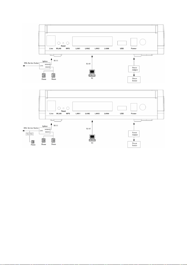
Figure 1 Without connecting telephone sets before the splitter
Figure 2 Connecting a telephone set before the splitter
6
3 Introduction to Web Configuration
Note:
The Web interface of software is for reference only.
This chapter describes how to use Web-based management of the DSL router,
which allows you to configure and control all of DSL router features and system
parameters in a user-friendly GUI.
3.1 Logging In to the Modem
The following description is a detail “How-To” user guide and is prepared for first
time users.
3.1.1 First-Time Login
When you log in to the DSL Router for the first time, the login wizard appears.
Step 1 Open a Web browser on your computer.
Step 2 Enter http://192.168.1.1 (default IP address of the DSL router) in the
address bar. The login page appears.
7
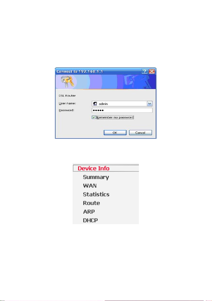
Step 3 Enter a user name and the password. The default username and
password are admin and admin. You need not enter the username and
password again if you select the option Remember my password. It is
recommended to change these default values after logging in to the DSL
router for the first time.
Step 4 Click OK to log in or click Cancel to exit the login page.
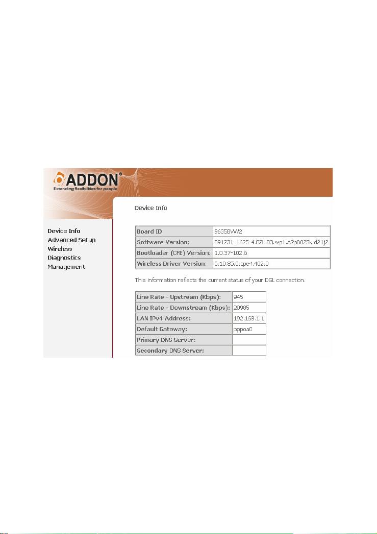
3.2 DSL Router Device Information
Choose Device Info, the following page appears.
8
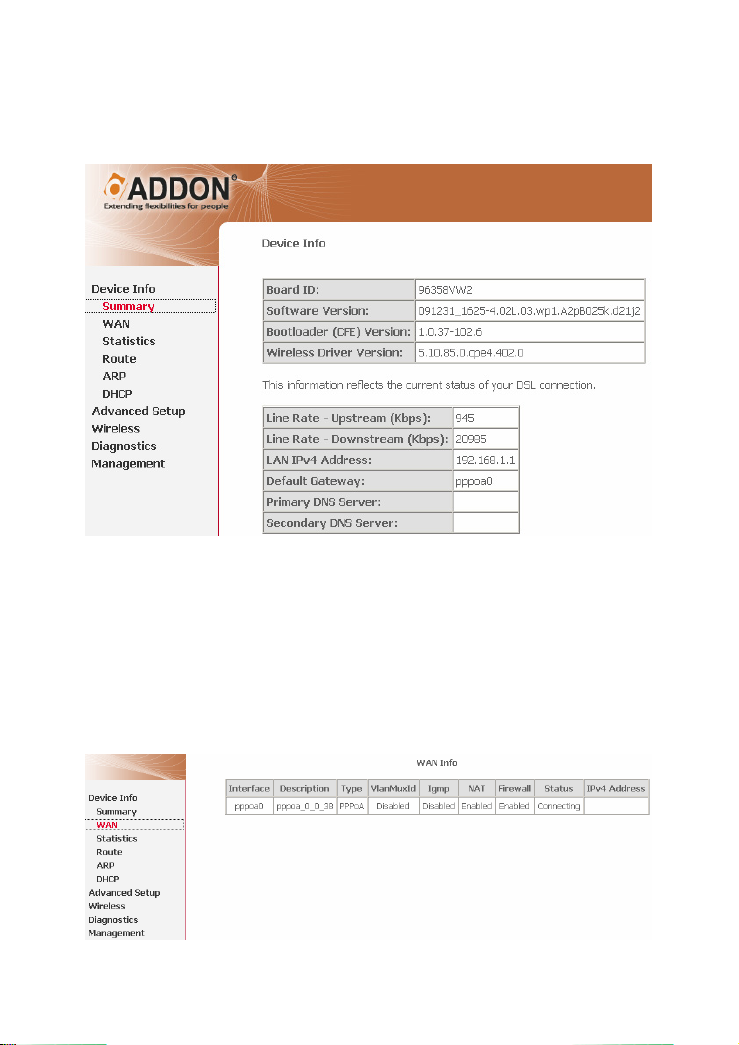
3.2.1 Summary of Device Information
Choose Device Info > Summary, the following page appears.
LAN IPv4 Address: The management IPv4 address.
Default Gateway: In the bridging mode there is no gateway. In other modes,
it is the address of the uplink equipment, for example, PPPoE/PPPoA.
DNS Server address: In the PPPoE/PPPoA mode, it is obtained from the
uplink equipment. In the bridging mode, there is no DNS Server address and
you can manually enter the information.
3.2.2 WAN Interface Information
Choose Device Info > WAN and the following page appears.
Description: Descripte this interface with protocol and PVC.
9
Type: The connection type of WAN, such as PPPoE, PPPoA.
3.2.3 Statistics
This page contains the following four parts:
Statistics of LAN
Statistics of WAN Service
Statistics of xTM
Statistics of xDSL
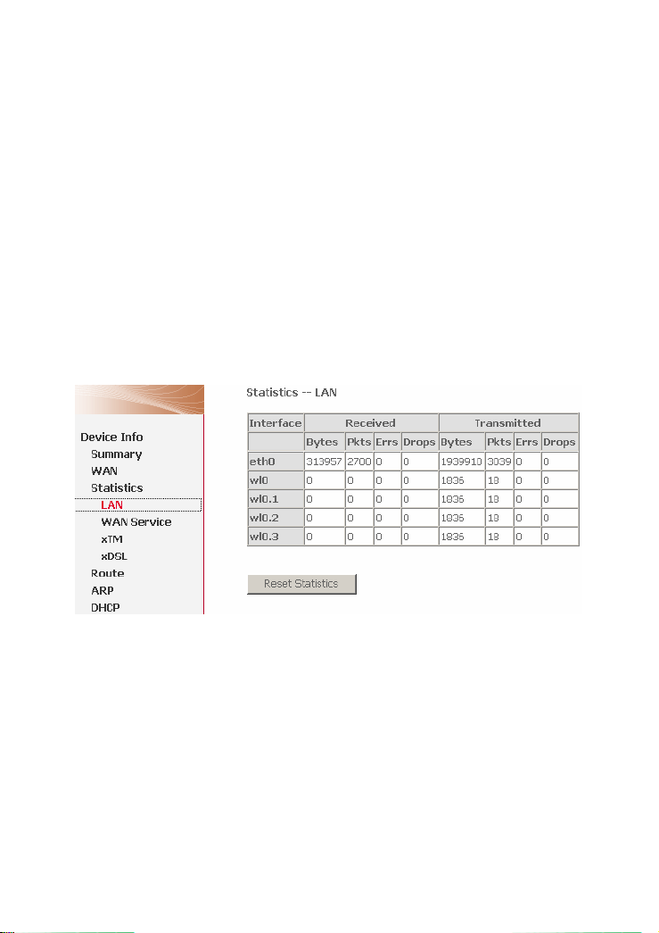
3.2.4 Statistics of LAN
Choose Device Info > Statistics > LAN and the following page appears. You can
query information of packets recevied at the Ethernet, USB, and wireless interfaces.
Click Reset Statistics to restore the values to zero and recount them.
The LAN side interface includes Ethernet USB and wireless device.
3.2.5 Statistics of WAN
Choose Device Info > Statistics > WAN Service and the following page appears.
You can query information of packets recevied by the WAN interfaces. Click Reset
Statistics to restore the values to zero and recount them.
10
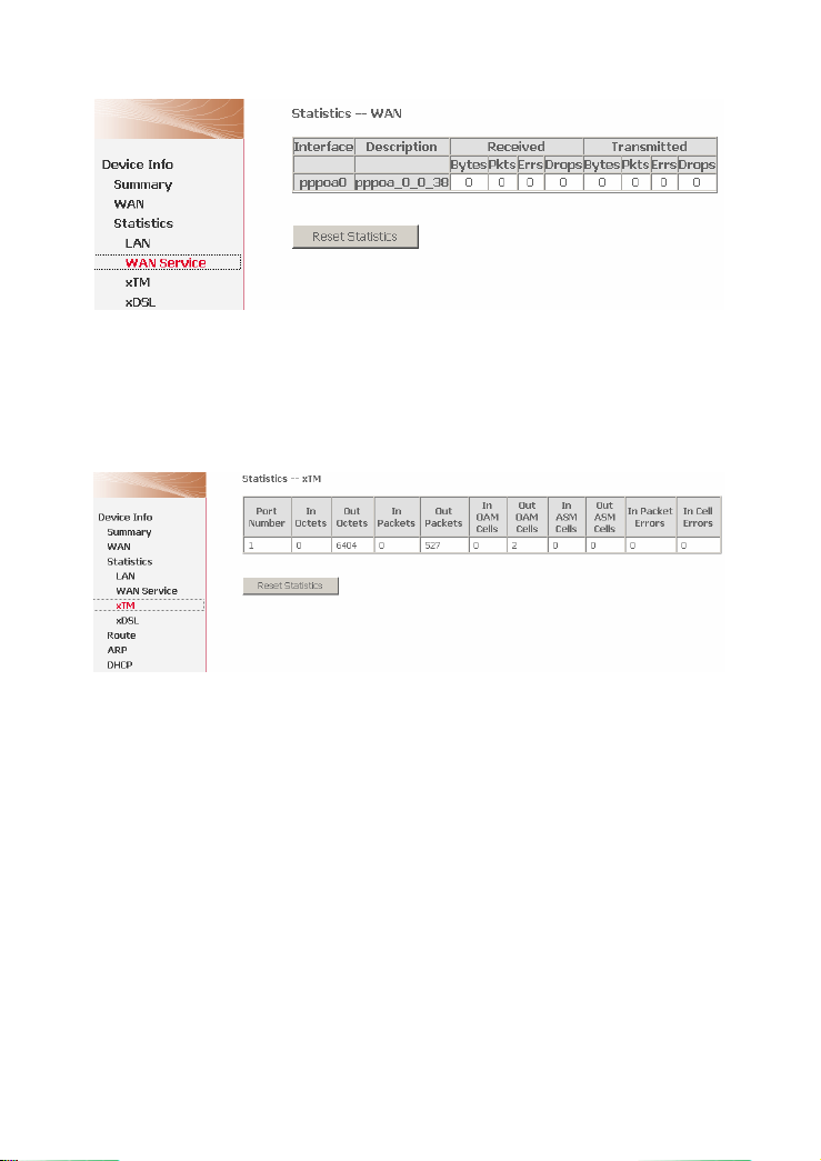
Figure 3 Statistics of WAN
3.2.6 Statistics of xTM
Choose Device Info > Statistics > xTM and the following page appears. You can
query information of packets recevied by the ATM interfaces. Click Reset
Statistics to restore the values to zero and recount them.
3.2.7 Statistics of xDSL
Choose Device Info > Statistics > xDSL and the following page appears.
If the DSL line is activated, the following window appears.
11
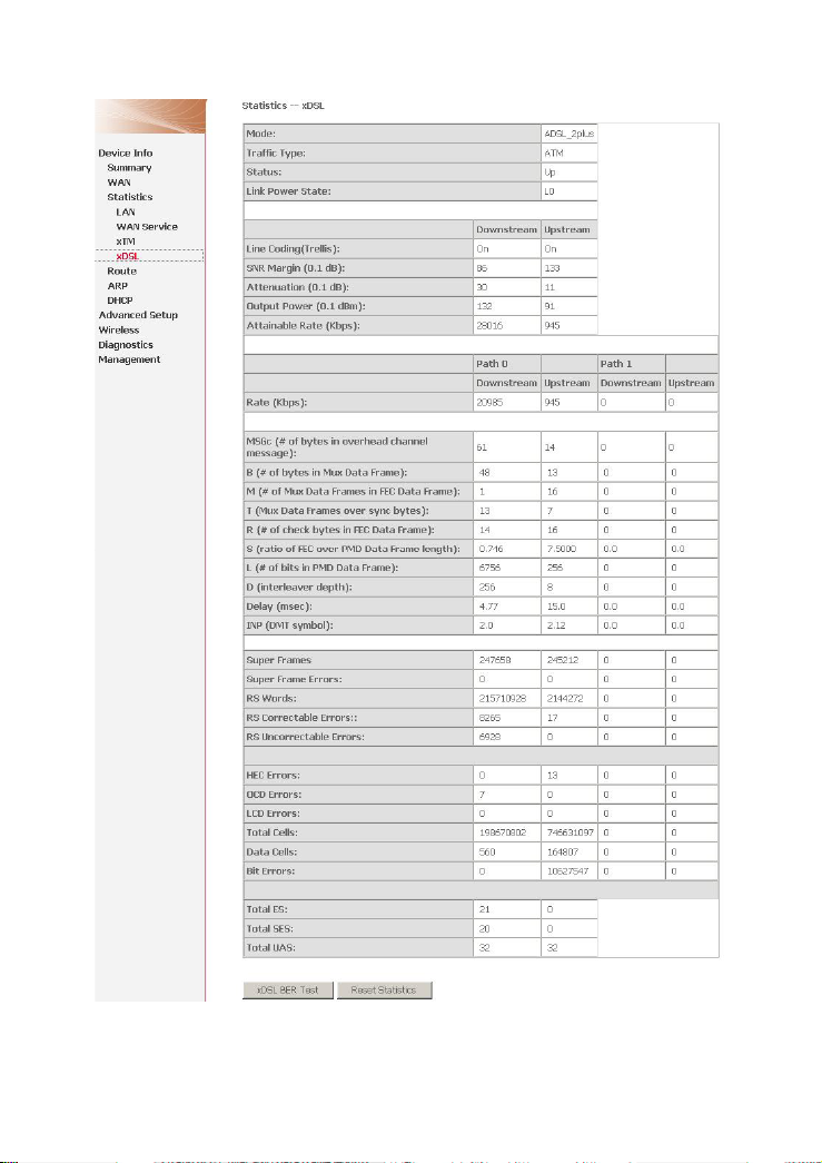
Traffic Type: ATM, or PTM.
Status: Up, NoSigal, Establishinglink
Link Power State: L0, L1, L2
12
Line Coding: Trallis on, etc.
Rate (Kbps): Upstream Line Rate/Downstream Line Rate.
Click Reset Statistics at the bottom to restore the values to zero and recount
them.
Click xDSL BER Test to test xDSL Bit Error Rate.
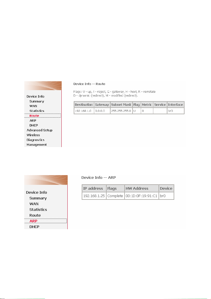
3.2.8 Route Table Information
Choose Device Info > Route and the following page appears.
3.2.9 ARP Table Information
Choose Device Info > ARP and the following page appears. You can query the
MAC and IP address information of the equipment attached to the modem.
3.2.10 DHCP IP Lease Information
Choose Device Info > DHCP and the following page appears. You can query the
IP address assignment for MAC address at the LAN side of the DSL router and
obtain the IP Address from the DHCP server through Ethernet and wireless in the
DSL router.
13
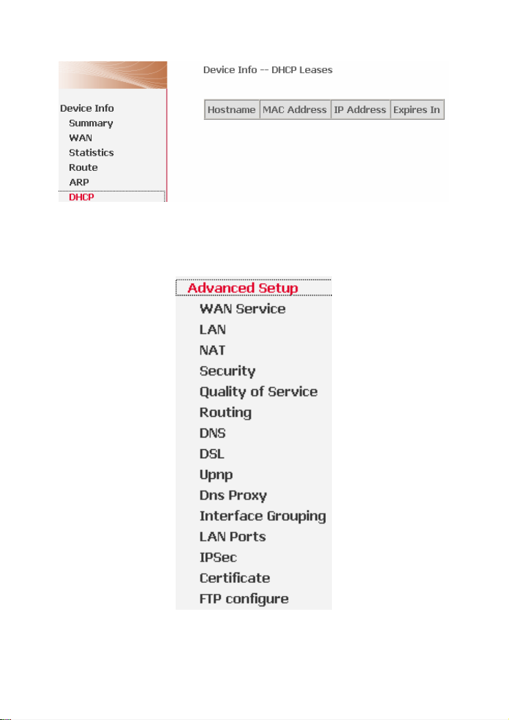
Expires In: Time that the device leases the IP Address for the MAC Address.
3.3 Advanced Setup
Choose Advanced Setup and the following page appears.
WAN Service: wide area network service interface configuration
LAN: local area network interface
Advanced Setup is key to DSL Router configuration.
14

3.3.1 WAN Configuration
Choose Advanced Setup > WAN Service, and the following page appears.
Figure 4 WAN configuration
Click Add to configure PPPoE, MER, Bridging, PPPoA, and IPoA WAN
configuration.
Choose Remove check box, click Remove to delete the WAN configuration.
3.3.1.1 PPPoE Configuration
This section describes the procedure for adding PVC 0/35 (PPPoE mode).
Click Add and the following page appears. In this page, you can modify VPI/VCI,
QoS and select the Internet connection type, encapsulation mode and service
category.
15
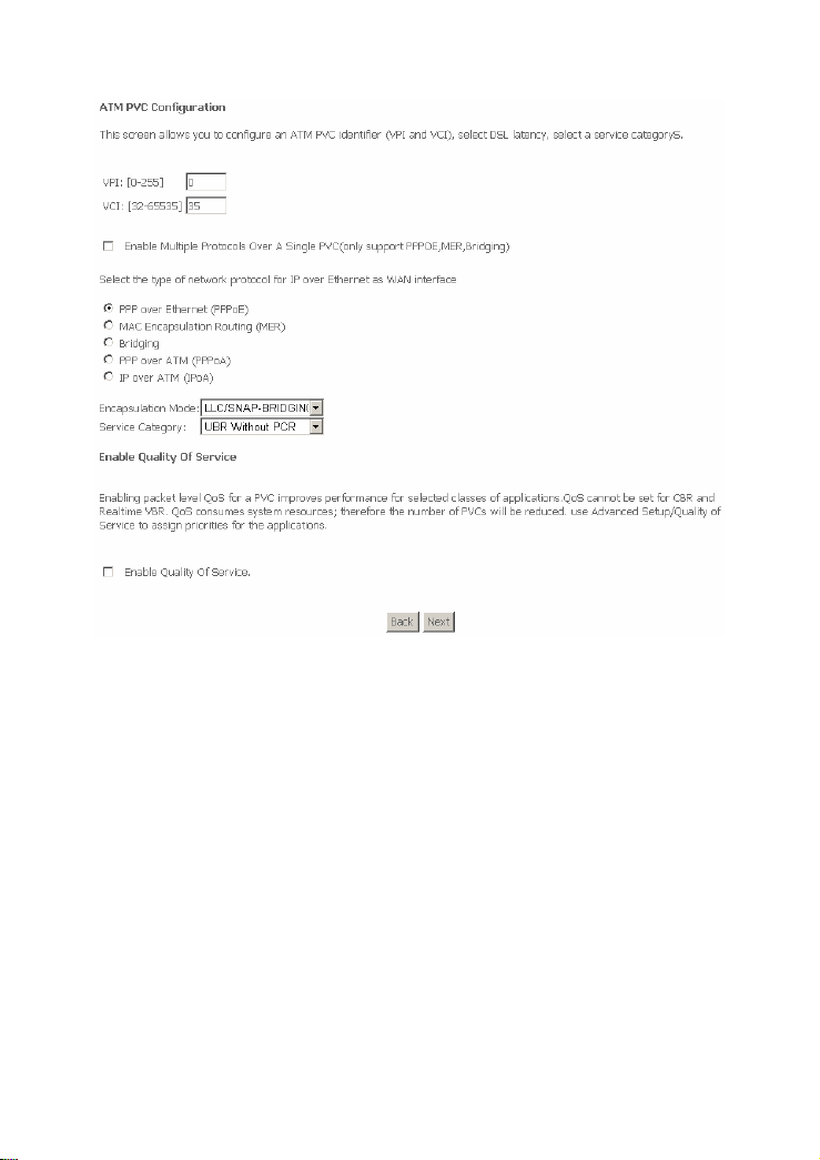
VPI: Virtual path between two points in an ATM network. Its valid value range
is from 0 to 255.
VCI: Virtual channel between two points in an ATM network. Its valid value
range is from 32 to 65535 (1 to 31 are reserved for known protocols).
Service Category: UBR Without PCR/UBR With PCR/CBR/Non Realtime
VBR/Realtime VBR.
Enable Quality Of Service: Enable or disable QoS.
In this example, PVC 0/35 is to be modified and the default values of service
category remain. In actual applications, you can modify them as required.
Change the connection type of PVC 0/35 to PPP over Ethernet (PPPoE) and set
the Encapsulation Mode to LLC/SNAP-BRIDGING (according to the uplink
equipment).
Click Next and the following page appears. In this page, you can modify the service
description and enable the 802.1Q VLAN.
16

Enable the 802.1Q VLAN and the following page appears.
Note:
The 802.1q VLAN tagging is only available for PPPoE, MER, and Bridge.
Click Next and the following page appears. In this page, you can modify the PPP
user name, PPP password, and authentication method.
17
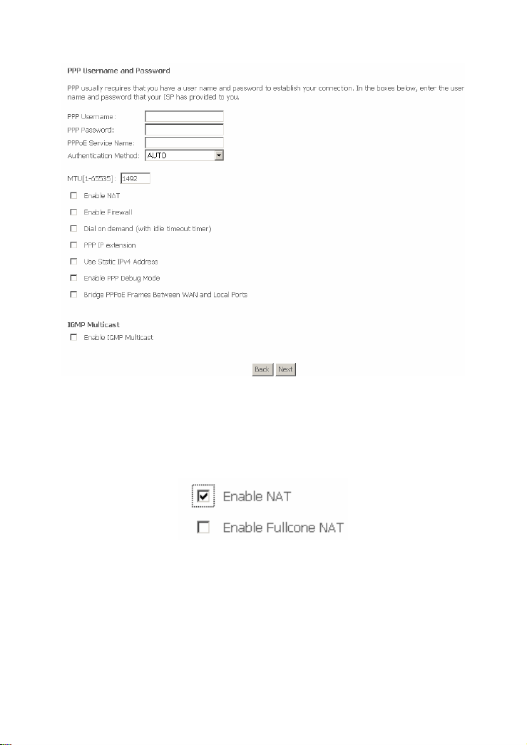
PPP Username: The correct user name that your ISP provides to you.
PPP Password: The correct password that your ISP provides to you.
Authentication Method: The value can be AUTO, PAP, CHAP, or MSCHAP.
Usually, you can select AUTO.
Enable NAT: If you enable NAT, the Enable Fullcone NAT check box
appears.
Enable Fullcone NAT: A full cone NAT is one where all requests from the
same internal IP address and port are mapped to the same external IP
address and port. Furthermore, any external host can send a packet to the
internal host, by sending a packet to the mapped external address.
Dial on demand (with idle timeout timer): If this function is enabled, you
need to enter the idle timeout time. Within the preset minutes, if the modem
does not detect the flow of the user continuously, the modem automatically
stops the PPPOE connection. Once it detects the flow (like access to a
webpage), the modem restarts the PPPoE dialup. If this function is disabled,
18
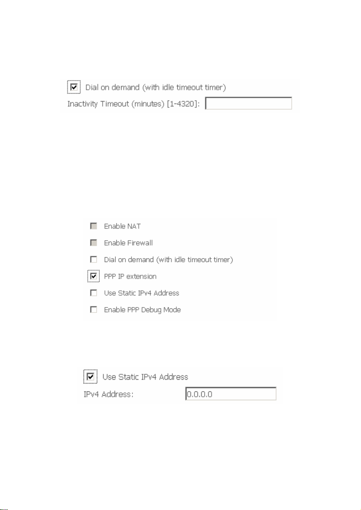
the modem performs PPPoE dial-up all the time. The PPPoE connnection
does not stop, unless the modem is powered off and DSLAM or uplink
equipment is abnormal.
PPP IP extension: After PPP IP extension is enabled, the following page
appears. The NAT and Firewall becom invalid, and the Bridge PPPoE
Frames Between WAN and Local Ports check box disappears. And the
WAN IP address obtained by the modem through built-in dial-up can be
directly assigned to the PC being attached with the modem (at this time, the
modem has only one PC). From the view of the PC user, this is even with that
the PC dials up to obtain an IP addres. But actually, the dial-up is done by the
modem. If this function is disabled, the modem itself obtains the WAN IP
address automatically.
Use Static IPv4 Address: If this function is disabled, the modem obtains an
IP address assigned by an uplink equipment such as BAS, through PPPoE
dial-up. If this function is enabled, the modem uses this IP address as the
WAN IP address.
Enable PPP Debug Mode: Enable or disable this mode of debug. This
service is designed for the professional engineer.
Bridge PPPoE Frames Between WAN and Local Ports: The PPPoE client
can connect to router or PC.
IGMP Multicast: IGMP proxy. For example, if you want PPPoE mode to
support IPTV, enable it.
19
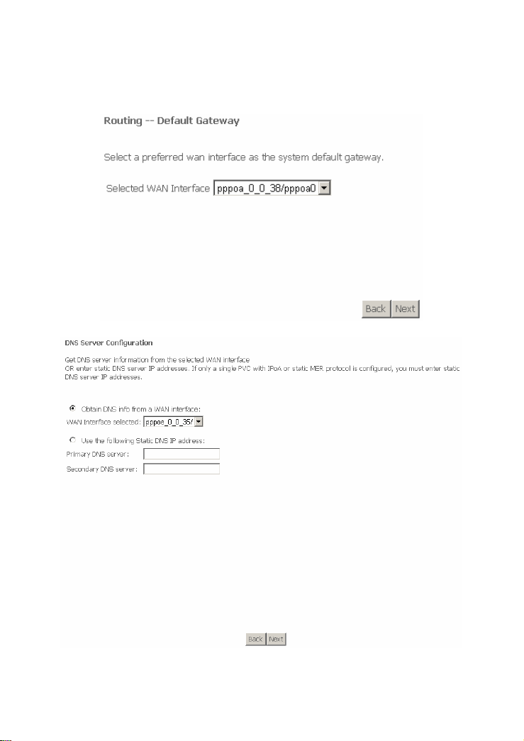
After proper configuration, click Next and the following page appears. In this page,
select a preferred WAN interface as the system default gateway.
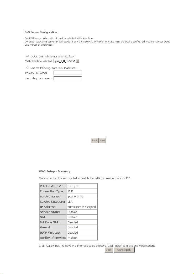
Click Next, and the following page appears.
20
In this page, you can get DNS server information from the selected WAN interface
or enter static DNS server IP addresses. If only a single PVC with IPoA or static
MER protocol is configured, you must enter static DNS server IP addresses.
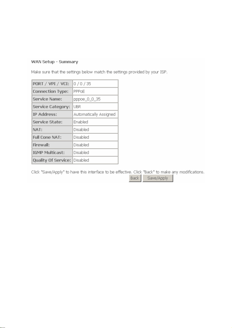
Click Next, and the following page appears.
In this page, it shows all the configurations. Click Save/Apply to all the
configurations. Click Back to make any modifications.
3.3.1.2 MER (IPoE) Configuration
Click Add and the following page appears. In this page, you can modify VPI/VCI,
QoS and select the Internet connection type, encapsulation mode and service
category.
21
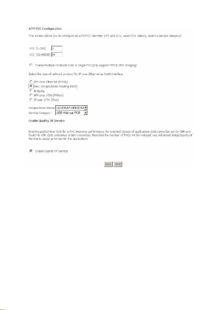
VPI: Virtual path between two points in an ATM network. Its valid value range
is from 0 to 255.
VCI: Virtual channel between two points in an ATM network. Its valid value
range is from 32 to 65535 (1 to 31 are reserved for known protocols).
Service Category: UBR Without PCR/UBR With PCR/CBR/Non Realtime
VBR/Realtime VBR.
Enable Quality Of Service: Enable or disable QoS.
Change the connection type of PVC 0/35 to MAC Encapsulation Routing (MER)
and set the Encapsulation Mode to LLC/SNAP-BRIDGING (according to the
uplink equipment).
Click Next and the following page appears. In this page, you can modify the service
description and enable the 802.1Q VLAN.
22

Enable the 802.1Q VLAN and the following page appears.
Note:
The 802.1q VLAN tagging is only available for PPPoE, MER, and Bridge.
Click Next and the following page appears.
23

In this page, you can modify the IP Settings. Enter information provided by your
ISP to configure the WAN IP settings.
Note:
If select Obtain an IP address automatically is chosen, DHCP will be enabled
for PVC in MER mode. If Use the following Static IP address is chosen, enter
the WAN IP address, subnet mask and interface gateway.
Click Next and the following page appears.
24
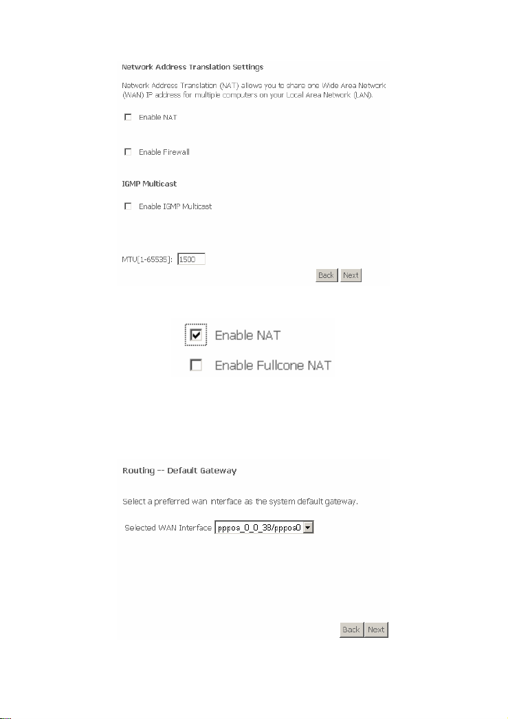
In this page, you can modify the Network Address Translation Settings. If you
enable NAT, the Enable Fullcone NAT check box appears.
Enable Fullcone NAT: A full cone NAT is one where all requests from the same
internal IP address and port are mapped to the same external IP address and port.
Furthermore, any external host can send a packet to the internal host, by sending a
packet to the mapped external address.
Click Next and the following page appears.
In this page, select a preferred wan interface as the system default gateway.
25
Click Next and the following page appears.
In this page, you can get DNS server information from the selected WAN interface
or enter static DNS server IP addresses. If only a single PVC with IPoA or static
MER protocol is configured, you must enter static DNS server IP addresses.
Click Next and the following page appears
26
In this page, it shows all the configurations. Click Save/Apply to all the
configurations. Click Back to make any modifications.
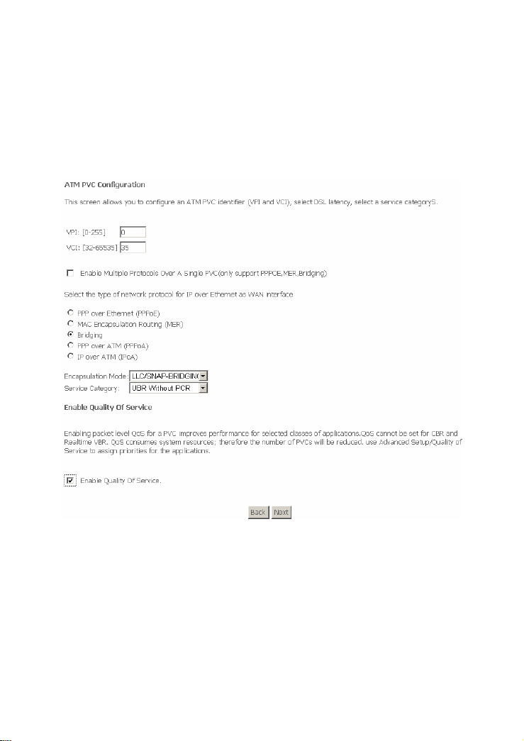
3.3.1.3 Bridging Configuration
Click Add and the following page appears. In this page, you can modify VPI/VCI,
QoS and select the Internet connection type, encapsulation mode and service
category.
VPI: Virtual path between two points in an ATM network. Its valid value range
is from 0 to 255.
VCI: Virtual channel between two points in an ATM network. Its valid value
range is from 32 to 65535 (1 to 31 are reserved for known protocols).
Service Category: UBR Without PCR/UBR With PCR/CBR/Non Realtime
VBR/Realtime VBR.
Enable Quality Of Service: Enable or disable QoS.
Change the connection type of PVC 0/35 to Bridging and set the Encapsulation
Mode to LLC/SNAP-BRIDGING (according to the uplink equipment).
27
 Loading...