

Additel 938 User Manual
Warningsand cautions
Operate the pump in the rated pressure range of 15,000 psi (1,000 bar)
and do not exceed the safety pressure of 18,000 psi (1,200 bar).
When the ystem ressure s reater han 10,000 psi you must close the
pre ressurization hut ff alve 7 and then pressurize he system with
sp igt ,
-p s o v (# ) t
the high pressure handle.
Close all valves and handles and tighten the ports when transporting the pump.
Always keep the reservoir cover vent valve #4 open during operation.
)(
Do not over tighten the valves, connectors and handles to avoid damage.
Change media immediately if it is contaminated.
Keep media level between 1/4 and 3/4 of the liquid reservoir filled.
Keep the threads clean and lubricious, and remove any dirt on threads.
Used by trained personnel only.
Additel is not liable for any safety problems or damages caused by misuse
or incorrect operation.
Specification
936/937/938
Hydraulic High Pressure Test Pump User's Manual
[Version number:1407V02]
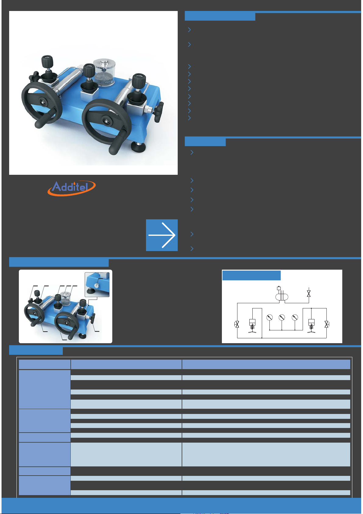
Views and Hydraulic Schematic
1- Vent valve
2- Over-flow reservoir
3- Quick connector
4- Reservoir cover vent valve
5- Reservoir
6- Liquid drain valve
7- Pre-pressure shut off valve
(Isol ates th e calib ration volume from the
pre-pressure side of the pump)
8- High-pressure and fine pressure
adjustment handle
9- Pre-pressure handle
1 32
6
4
5
9
7
8
Pressure range: 12.5 psi ( 0.85 bar ) vacuum to
15,000 psi ( 1000 bar ) positive pressure
Remark:If local atmosphere pressure is 1 bar, the vacuum can reach to 0.85 bar;
If local atmosphere pressure is P, the vacuum can reach to bar.( P 85% )
Temperature:
(5 ~ 50)℃
Adjustment resolution: 0.015 psi ( 1 mbar )
Safety pressure: <18,000 psi (1,200 bar)
Pressure media:
ADT936: Diethylhexyl Sebacate
ADT938: Deionized water
ADT937 :Oil,compatible to phosphoric acid ester fluid and Skydrol oil.
Size: Height: 10.43'' ( 265 mm )
Base: 20.71'' ( 526 mm ) x 9.65'' ( 245 mm )
Weight: 35.5 lb ( 16 kg )
Hydraulic Schematic
5
1
9
8
7
Troubleshooting
Problem
It is difficult to generate
pressure with the
pre-pressure
handle (#9)
It is difficult to
pressurize by turning
the high-pressure
handle (#8)
It is difficult to generate
high vacuum
Hard to pressurize
large-volume DUT
Pressure gauges do not
reach to zero
Hard to turn the
valves or handles
Cause
Vent (#1) is not closed
The O-ring in quick connector is missing, misplaced, or broken
Pre-pressure shut off valve (#7) is closed
Not enough media is in the reservoir.
Too much air is in the pump (see purge section of the manual)
Max pressure generation (could be as low as 5,000 psi, 350 bar) is
achieved with the pre-pressure handle (#9)
The pre-pressure shut off valve (#7) is not closed completely
Reference gauge or devices under test (DUTs) are not connected tightly
The O-ring in quick connector is missing, , or broken
The end surface of the DUT connection thread is not smooth
The connector of the DUT is not matched to quick connector
Purge the air from the system (see purge section of the manual)
#4 valve is not open
Because of the large volume of the DUT, it will take additional steps to
fill the volume to pressurize the DUT
#4 valve is not open
Too much force was previously applied
Hard to turn pre-pressure handle (#9) at high pressure
Lack of lubrication on threads
misplaced
Solution
Close vent valve (#1)
Replace with a new O-ring
Open pre-pressure shut off valve (#7). Caution: the pre-pressure side of the pump should not be exposed to
more than 10,000 psi (700 bar).
Fill more media, and keep media level between 1/4 and 3/4 of the liquid reservoir filled
Purge the air from the system (see purge section of the manual)
Close pre-pressure shut off valve and use high-pressure and handle (#8).
Close pre-pressurization shut off valve (#7)
Check finger-tight connectors, re-tight if necessary
Replace with a new O-ring
Use a PTFE washer in finger-tight connector
Use proper adapter
Purge the air from the system (see purge section of the manual)
Open the #4 valve
Step 1: Turn pre-pressure handle (#9) all the way in clockwise, close pre-pressure shut off valve (#7),
open vent valve (#1).
Step 2: Turn pre-pressure handle (#9) all the way counterclockwise, close vent valve (#1).
Step 3: Open pre-pressure shut off valve (#7), pressurize the system.
Step 4: Repeat step 1 to 3.
Open the #4 valve
Do not over tighten
This is normal. Close the pre-pressure shut off valve (#7) and use the high-pressure handle to adjust the
pressure.
Lubricate the threads

Maintenance
Fill media Drain and Clean
Note: In order to properly generate pressure,
the gas must be purged from the pump
(see purge process below).
①open reservoir
cover vent valve (#4)
Basic Operation
Note: Gauge positions are interchangeable. Any open ports should be plugged prior to operation.
DIGITALPRESSURECALIBRATOR
Units
bar
A
0255075100
A
②fill media
64 96
Pressure Gauge
Bar
32
128
160
SW V mA COM 24V
③ Open reservoir cover
vent valve (#4)
④ Unscrew with
hex wrench
⑤Remove the
reservoir(#5)
①Open drain valve (#6)
②Collect media using a container
Connection
SW V mA COM 24VSW V mA COM 24V
A
B
⑤ Vacuum displayed
on the gauge
DIGITALPRESSURECALIBRATOR
Units
b
bar
a
r
A
0255075100
③close
④Turn all the way out
Purge pocess
①Always keep valve(#4)
open during operation
B
②open
③open
④open
Purge process (cont.)
DIGITALPRESSURECALIBRATOR
Units
0255075100
If air is still trapped in the pump,
then repeat the purge process
2 or 3 more t imes un til all t he
b
bar
a
r
A
gas is re moved f rom the s ystem
④Wait for gauge to vent to zero
Bubbles
⑤Turn all the way in
Depressurizing process
DIGITALPRESSURECALIBRATOR
Units
b
bar
a
r
A
0255075100
③depressurizing
64 96
Pressure Gauge
Bar
32
①Always keep valve(#4)
open during operation
128
160
64 96
32
①depressurizing
DIGITALPRESSURECALIBRATOR
0 25 50 75 100
pressure transmitter
b
bar
a
r
A
Zeroing Pressurizing process
64 96
Pressure Gauge
Bar
32
128
160
①always keep valve(#4)
open during operation
dial gauge
C
pressure switch
Units
②open
②open
F G
DIGITALPRESSURECALIBRATOR
Units
①close
0255075100
②Vacuum
Pressure Gauge
Bar
128
160
②open
Vacuum process Vent
If it is difficult to generate vacuum
pressure, then repeat the purging
proce ss to mak e sure al l the gas
is remo ved fro m the sys tem
b
bar
a
r
A
0.6 0.4
Pressure Gauge
Bar
0.8
0.2
0
-1
64 96
Pressure GaugePressure Gauge
Bar
32
0.6 0.4
Pressure Gauge
Bar
0.8
-1
flexible hose
D
128
160
③open
0.2
0
①close
②open
DIGITALPRESSURECALIBRATOR
Units
b
bar
a
r
A
0255075100
②Pre-pressure
DIGITALPRESSURECALIBRATOR
Units
b
bar
a
r
A
0255075100
①back to atmosphere
E
Note: Skip step for dial gauge
64 96
Pressure GaugePressure Gauge
Bar
32
0.6 0.4
Pressure Gauge
0.8
-1
③
calibration in a narrow
pressure range.
128
160
64 96
Pressure GaugePressure Gauge
Bar
32
128
160
④high-pressure
Bar
0.2
0
0.6 0.4
Pressure Gauge
Bar
0.8
0.2
0
-1
③close
H
Remark:
A Additel has made a concerted effort to provide complete and current information for the proper use of the equipment. The product specifications and other information contained this manual are
subject to change without notice.
B:: Above pictures are just for reference.
Additel Corporation, USA
www.additel.com
 Loading...