

Page 1

I
Additel 761A Automated Pressure Calibrator
————User Manual
Please download the latest version from www.additel.com
[Version:1911V01]
Additel Corporation
Page 2

II
STATEMENT
This user manual provides operating and safety instructions for the ADT761A Automated Pressure
Calibrator. To ensure correct operation and safety, please follow the instructions in this manual.
Additel Corporation reserves the right to change the contents and other information contained in this
manual without notice.
Page 3

III
CONTENT
Warnings ............................................................................................................................................................... 1
General safety ....................................................................................................................................................... 2
1. Introduction ...................................................................................................................................................... 3
1.1 Overview ................................................................................................................................................. 3
1.2 Features ................................................................................................................................................... 3
1.3 Environmental Conditions ....................................................................................................................... 4
1.4 Power ...................................................................................................................................................... 4
1.5 Specifications .......................................................................................................................................... 4
2. Installation....................................................................................................................................................... 10
2.1 Features ................................................................................................................................................. 10
2.1.1 Basic structure ............................................................................................................................ 10
2.1.2 Electrical and signal port ............................................................................................................ 12
2.1.3 Keypad ........................................................................................................................................ 13
2.1.4 Pressure ports ............................................................................................................................ 14
2.2 Initial preparation.................................................................................................................................. 15
2.2.1 Battery installation ..................................................................................................................... 15
2.2.2 Changing the shoulder strap ...................................................................................................... 16
2.2.3 Pressure connection ................................................................................................................... 18
2.2.4 View the display ......................................................................................................................... 19
2.3 Getting started ...................................................................................................................................... 19
Page 4

IV
2.3.1 Power on .................................................................................................................................... 19
2.3.2 Setting the system date and time .............................................................................................. 20
2.3.3 Generating a pressure ................................................................................................................ 20
2.3.4 Display and operation ................................................................................................................ 20
3. Display and Operation ..................................................................................................................................... 20
3.1 Home screen ......................................................................................................................................... 20
3.1.1 Status bar ................................................................................................................................... 21
3.1.2 Module and split screen display area ......................................................................................... 23
3.1.3 Main interface keypad operation ............................................................................................... 23
3.2 Pressure control .................................................................................................................................... 24
3.2.1 Pressure output .......................................................................................................................... 24
3.2.2 Pressure measurement .............................................................................................................. 27
3.2.3 Pressure unit .............................................................................................................................. 28
3.3 Electrical signal measurement .............................................................................................................. 28
3.3.1 Current/Voltage measurement .................................................................................................. 29
3.3.2 Switch test .................................................................................................................................. 32
3.3.3 HART Communication ................................................................................................................ 33
3.3.4 PROFIBUS PA communication .................................................................................................... 41
3.4 Electrical output .................................................................................................................................... 43
3.5 External pressure module ..................................................................................................................... 47
3.6 Typical applications ............................................................................................................................... 49
3.6.1 Pressure gauge ........................................................................................................................... 49
Page 5

V
3.6.2 Pressure transmitter................................................................................................................... 50
3.6.3 HART transmitter........................................................................................................................ 53
3.6.4 Pressure switch .......................................................................................................................... 54
3.6.5 I/P converter .............................................................................................................................. 55
4.1 Control settings ..................................................................................................................................... 57
4.2 Communication ..................................................................................................................................... 59
4.2.1 Ethernet ..................................................................................................................................... 59
4.2.2 Wireless communication............................................................................................................ 60
4.2.3 Bluetooth ................................................................................................................................... 61
4.3 Power management .............................................................................................................................. 62
4.3.1 Display brightness ...................................................................................................................... 62
4.3.2 Battery information .................................................................................................................... 62
4.3.3 Energy settings ........................................................................................................................... 62
4.4 System calibration ................................................................................................................................. 63
4.4.1 Calibration of electrical measurement ....................................................................................... 64
4.4.2 Auto tune ................................................................................................................................... 65
4.4.3 Calibration of the supply pressure module ................................................................................ 66
4.4.4 Calibration of the barometric pressure module ......................................................................... 66
4.4.5 Pressure calibration .................................................................................................................... 68
4.5 Services ................................................................................................................................................. 69
4.5.1 System upgrade .......................................................................................................................... 69
4.5.2 Maintenance .............................................................................................................................. 70
Page 6

VI
4.5.3 Factory reset ............................................................................................................................... 71
4.6 Personalization ...................................................................................................................................... 71
4.6.1 Date and time ............................................................................................................................. 72
4.6.2 Language .................................................................................................................................... 72
4.6.3 Sound ......................................................................................................................................... 72
4.7 Cloud service ......................................................................................................................................... 74
4.8 Data management ................................................................................................................................. 74
4.9 Product information .............................................................................................................................. 74
4.9.1 Host information ........................................................................................................................ 76
4.9.2 Control board information ......................................................................................................... 76
4.9.3 Electrical measurement board information ............................................................................... 76
4.9.4 Electrical source board information ........................................................................................... 76
4.9.5 Wireless module information .................................................................................................... 77
4.9.6 PROFIBUS module information .................................................................................................. 77
4.9.7 HART handheld communicator information .............................................................................. 77
5. Documentation ............................................................................................................................................... 77
5.1 Quick test .............................................................................................................................................. 77
5.1.1 Pressure gauge ........................................................................................................................... 77
5.1.2 Pressure transmitter................................................................................................................... 79
5.1.3 Pressure switch .......................................................................................................................... 80
5.1.4 Pressure sensor .......................................................................................................................... 81
5.1.5 I/P converter .............................................................................................................................. 81
Page 7

VII
5.1.6 Signal isolator ............................................................................................................................. 82
5.2 Task ........................................................................................................................................................ 82
5.2.1 Analog pressure gauge ............................................................................................................... 82
5.2.2 Digital pressure gauge ................................................................................................................ 89
5.2.3 Calibrate a pressure transmitter ................................................................................................ 90
5.2.4 Pressure transducer ................................................................................................................... 93
5.2.4 Pressure switch .......................................................................................................................... 95
5.2.6 I/P converter .............................................................................................................................. 98
5.2.7 Signal isolator ........................................................................................................................... 100
5.2.8 Contact pressure gauge ............................................................................................................ 102
5.2.9 Valve opening gauge ................................................................................................................ 106
5.3.2 Mercury barometer .................................................................................................................. 110
5.3.3 Aneroid barometer ................................................................................................................... 111
5.3.4 Barometric altimeter ................................................................................................................ 112
5.3.5 Pressure transmitter................................................................................................................. 113
5.3.6 Pressure switch ........................................................................................................................ 113
5.4 Task (for barometric (BP) version) ....................................................................................................... 114
5.4.1 Digital barometer ..................................................................................................................... 114
5.4.2 Calibration of the mercury barometer ..................................................................................... 116
5.4.3 Aneroid barometer ................................................................................................................... 119
5.4.4 Barometric altimeter ................................................................................................................ 121
5.4.5 Pressure transmitter................................................................................................................. 122
Page 8

VIII
5.4.6 Pressure switch ........................................................................................................................ 122
6. Application .................................................................................................................................................... 123
6.1 Unit conversion ................................................................................................................................... 123
6.2 Pressure leak test ................................................................................................................................ 123
7. HART Communication ................................................................................................................................... 126
7.1 HART connection and search .............................................................................................................. 126
7.2 HART communicator operation ........................................................................................................... 126
8. System maintenance ..................................................................................................................................... 128
8.1 Device information view ..................................................................................................................... 128
8.2 Diagnostic information ........................................................................................................................ 128
8.3 Check the sealing performance of the calibrator ................................................................................ 128
8.5 Replacement of the filter at the air pressure output interface and the O-ring................................... 130
8.6 Air filter replacement .......................................................................................................................... 132
Page 9

IX
Table Content
1. Introduction
Table 1- 1 Specifications .......................................................................................................................................................... 5
Table 1- 2 Electrical measurement specification ........................................................................................................... 7
Table 1- 3 General Index .......................................................................................................................................................... 9
1. Installation
Table 2- 1 Electrical and signal port .......................................................................................................... 13
Table 2- 2 Keypad function .......................................................................................................................... 14
2. Display and operation
Table3- 1 Setting interface ................................................................................................................................................... 27
Table3- 2 Scaling parameters ............................................................................................................................................. 31
Table3- 3 Filtering parameters .......................................................................................................................................... 32
Table3- 4 Hart Parameters .................................................................................................................................................. 38
Table3- 5 Automatic step parameters ............................................................................................................................ 46
Table3- 6 Slope output parameters .................................................................................................................................. 47
3. Control setting
Table 4- 1 Network connection ................................................................................................................... 59
Table 4- 2 Static mode selection ................................................................................................................. 60
Table 4- 3 Wireless network selection ........................................................................................................ 60
Table 4- 4 Setup of wireless communication .............................................................................................. 61
Page 10

X
Table 4- 5 Bluetooth setup .......................................................................................................................... 62
Table 4- 6 Date and time ............................................................................................................................. 72
Table 4- 7 Sound setup ................................................................................................................................ 73
Table 4- 8 Setup of cloud service ................................................................................................................ 74
4. Documentation test
Table 5- 1 Task analog pressure gauge information .................................................................................... 84
Table 5- 2 Task setting of analog pressure gauge ........................................................................................ 86
Table 5- 3 Task save ..................................................................................................................................... 88
Table 5- 4 Task pressure transmitter information ....................................................................................... 92
Table 5- 5 Task pressure sensor information ............................................................................................... 95
Table 5- 6 Task pressure switch information ............................................................................................... 97
Table 5- 7 Task I/P converter information ................................................................................................... 99
Table 5- 8 Task signal isolator information ................................................................................................ 101
Table 5- 9 Task contact pressure gauge information ................................................................................. 104
Table 5- 10 Task setting of contact pressure gauge ................................................................................... 105
Table 5- 11 Task valve opening gauge information ................................................................................... 108
Table 5- 12 Task digital barometer ............................................................................................................ 116
Table 5- 13 Task mercury barometer ......................................................................................................... 118
Table 5- 14 Task barometric altimeter....................................................................................................... 122
Page 11

XI
Figure Content
2. Installation
Figure 2- 1 Basic structure .................................................................................................................................................. 10
Figure 2- 2 Electrical and signal port .............................................................................................................................. 12
Figure 2- 3 Battery installation .......................................................................................................................................... 16
Figure 2- 4 Changing the shoulder strap ........................................................................................................................ 17
Figure 2- 5 Gauge pressure connection ......................................................................................................................... 18
Figure 2- 6 Low pressure and differential pressure connection ......................................................................... 19
3. Display and operation
Figure 3- 1 home screen ...................................................................................................................................................... 21
Figure 3- 2 Differential pressure outlet ......................................................................................................................... 24
Figure 3- 3 Gauge pressure outlet .................................................................................................................................... 25
Figure 3- 4 Pressure Measurement ................................................................................................................................. 28
Figure 3- 5 Current measurement ................................................................................................................................... 30
Figure 3- 6 Voltage measurement .................................................................................................................................... 30
Figure 3- 7 Switch test connection .................................................................................................................................. 33
Figure 3- 8 HART communication ................................................................................................................................... 34
Figure 3- 9 HART communication ................................................................................................................................... 35
4. Control setting
Figure 4- 1 Calibrate an atmospheric pressure module .......................................................................................... 67
5. Documentation test
Page 12

XII
Figure 5- 1 Calibration of digital pressure .................................................................................................................... 89
Figure 5- 2 Calibration of the pressure sensor ........................................................................................................... 93
Figure 5- 3 Calibration of the signal isolator ............................................................................................................ 100
Figure 5- 4 Calibration of the contact pressure gauge .......................................................................................... 102
Figure 5- 5 Calibration of the valve opening gauge ............................................................................................... 106
Figure 5- 6 Calibration of the general digital barometer ..................................................................................... 114
Figure 5- 7 Calibration of the digital barometer ..................................................................................................... 115
Figure 5- 8 Calibration of the mercury barometer ................................................................................................ 117
Figure 5- 9 Calibration of the aneroid barometer .................................................................................................. 120
Figure 5- 10 Calibration of the barometric altimeter ............................................................................................ 120
8. System maintenance
Figure 8- 1 Disassembly of the suction filter ............................................................................................................ 129
Figure 8- 2 Disassembly of air pressure/high-precision/barometric (BP) version pressure connector
............................................................................................................................................................................................ 130
Figure 8- 3 Disassembly of differential pressure/micro-differential pressure connector ................... 131
Figure 8- 4 Disassembly and assembly of the air filter ........................................................................................ 132
Page 13

1
Warnings
◆ Do not combine with another pressure source where pressure is being generated by both sources at the same
time.
◆ Do not apply pressures greater than the maximum working pressure.
◆ Not for use in flammable, high humidity, or dusty environments.
◆ Do not expose the battery of unit to fire.
◆ Charge the battery only using the Additel adapter. Please follow proper recycling procedures when discarding the
battery.
Page 14

2
General safety
◆ Do not shake, drop or bump the calibrator while in use.
◆ If condensation has occurred, thoroughly dry out the 761A before startup.
◆ Connecting the REF port to the reference port of unit under test (UUT) with a small differential
pressure range might result in control problems over time as the environmental temperature
changes. Recommend low pressure port of UUT connect REF port to resolve control issues.
◆ The vent port should not face the operator during venting.
◆ Do not apply more than 30V between any two electrical jacks (except for voltage measurement
jacks)
◆ Do not use any adapter other than Additel power adapter designed for the ADT761A. Charge the
battery as soon as the battery symbol indicates.
◆ If the calibrator is not working properly, turn it off, remove the battery and contact Additel.
◆ Do not remove the battery while it is charging or when the calibrator is in use.
◆ Before turning off the calibrator, make sure the system pressure is reduced to the atmosphere
pressure.
Page 15

3
1. Introduction
1.1 Overview
The ADT761A Automated Pressure Calibrator is completely self-contained and automated with a
built-in pump for pressure generation and precision control technology. ADT761A has many
improvements over the previous calibrator:
Increased pressure range to 1,000 psi (70 bar), removable internal pressure modules, optional
precision modules, touch screen display, Wi-Fi, Bluetooth, and Ethernet communications, double the
original battery life, and more!
1.2 Features
◆ Automated and self-contained pressure generation and control to 1,000 psi (70 bar)
◆ Standard accuracy to 0.02%FS
◆ Optional precision accuracy models to 0.01%FS
◆ Two removable internal pressure modules for multi-range selection
◆ Control stability to 0.003%FS
◆ Portable, designed for use in the field and in the lab
◆ Ability to measure two external pressure modules
◆ Wi-Fi, Bluetooth, USB and Ethernet communication
◆ HART and profibus communication
Page 16
4
◆ Data logging and task management
◆ Patented electric pump technology and improved speed
1.3 Environmental Conditions
◆ Using temperature: (0-50) °C
◆ Storage temperature: (-20-70) °C
◆ Environment humidity:<90%RH, Non-condensation
◆ Barometric pressure: (86~106)KPa
1.4 Power
◆ Working time: 12 hours
◆ Charging mode: charging with the unit or independently
◆ Charging time: less than 5 hours
1.5 Specifications
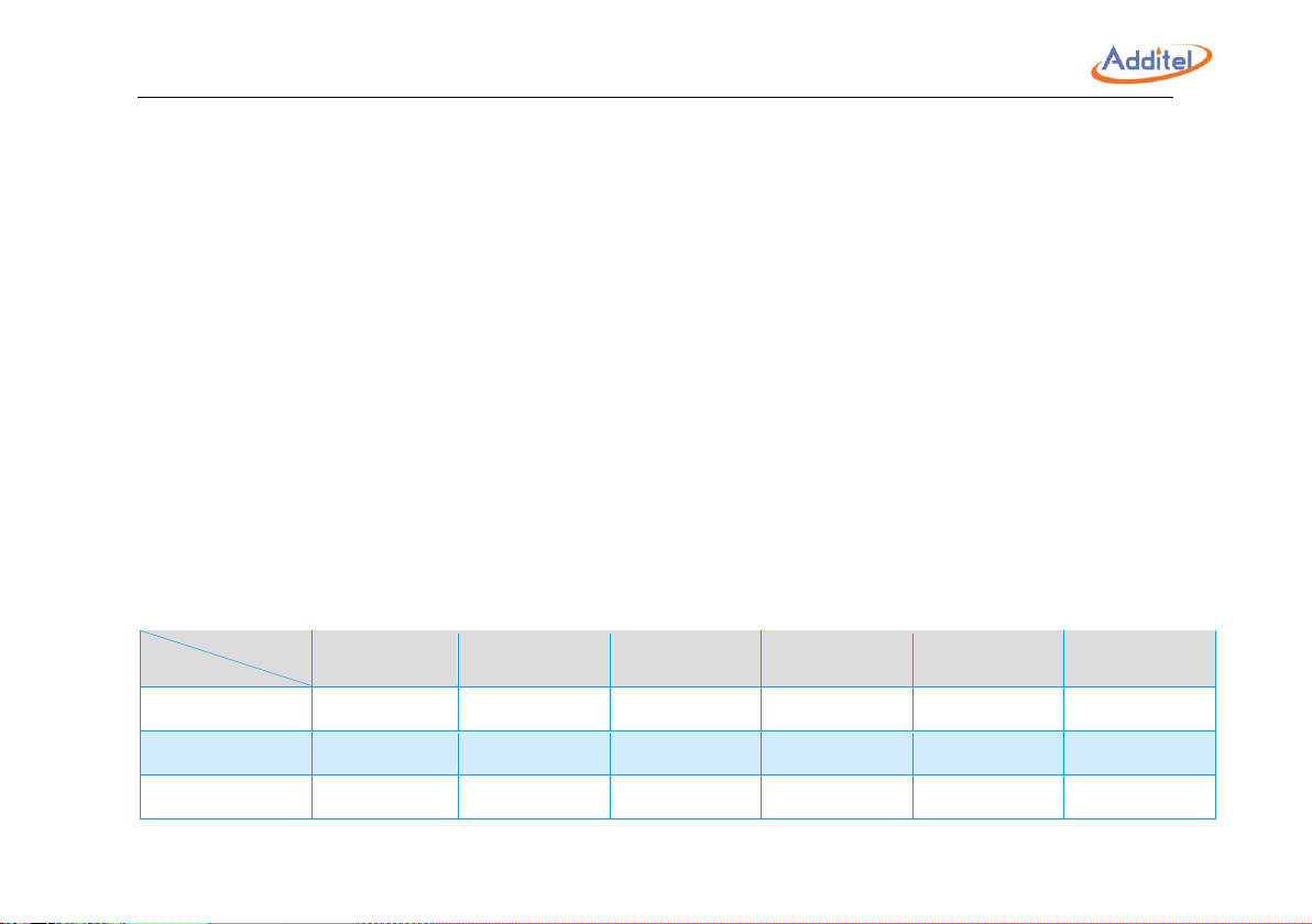
761A-LLP
761A-D
761A-500
761A-1K
761A-APXR
761A-BP
Max Pressure Range
30 inH2O (75
35 psi (2.5 bar)
500 psig (35 bar.g)
1,000 pisg (70
Dependent on
1,200 hPa
Min Pressure Range
-30 inH2O (-75
-13.5 psi (-0.95 bar)
-13 psi (-0.9 bar)
-13 psi (-0.9 bar)
Dependent on
100 hPa
Accuracy(1)
0.05%FS
0.02%FS
0.02%FS
(2)
0.02%FS
(2)
0.01%FS
0.01%FS
Page 17
5
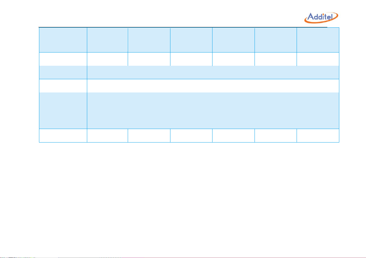
Stability
0.005%FS or 0.05
Pa
0.005%FS
0.005%FS
0.005%FS
0.003%FS
0.02 hPa
Pressure Type
Differential, Gauge
Differential, Gauge
Gauge, Absolute
Gauge, Absolute
Gauge, Absolute
Absolute
Over Range Indication
120%
Resolution
6 digits
Measurement Units
Pa, hPa, kPa, mPa, bar, mbar, psi, mmHg@0°C, cmHg@0°C, mHg@0°C, inHg@0°C, inH2O@4°C, mmH2O@4°C,
cmH2O@4°C, mH2O@4°C, mmH2O@20°C, cmH2O@20°C, mH2O@20°C, inH2O@20°C, kg/m2, mtorr, torr, lb/ft2, tsi,
custom
Barometric Accuracy
N/A
N/A
±60 Pa
±60 Pa
±60 Pa
N/A
Table 1- 1 Specification
[1] One year accuracy (including 1 year stability). FS specification applies to the span of the module
range.
[2] Specification based on gauge measurement. An additional 60 pa uncertainty will need to be
included when measuring in absolute mode. Applicable only for use with the ADT761A-500 and
ADT761A-1K
◆ Stability: 0.005%FS or 0.05 Pa, whichever is greater. 761A-BP: 0.02 hPa
◆ Control response time: 20%FS pressure step, external 50cc volume access, high speed
mode,<30 seconds;
◆ Media: Air
Page 18
6
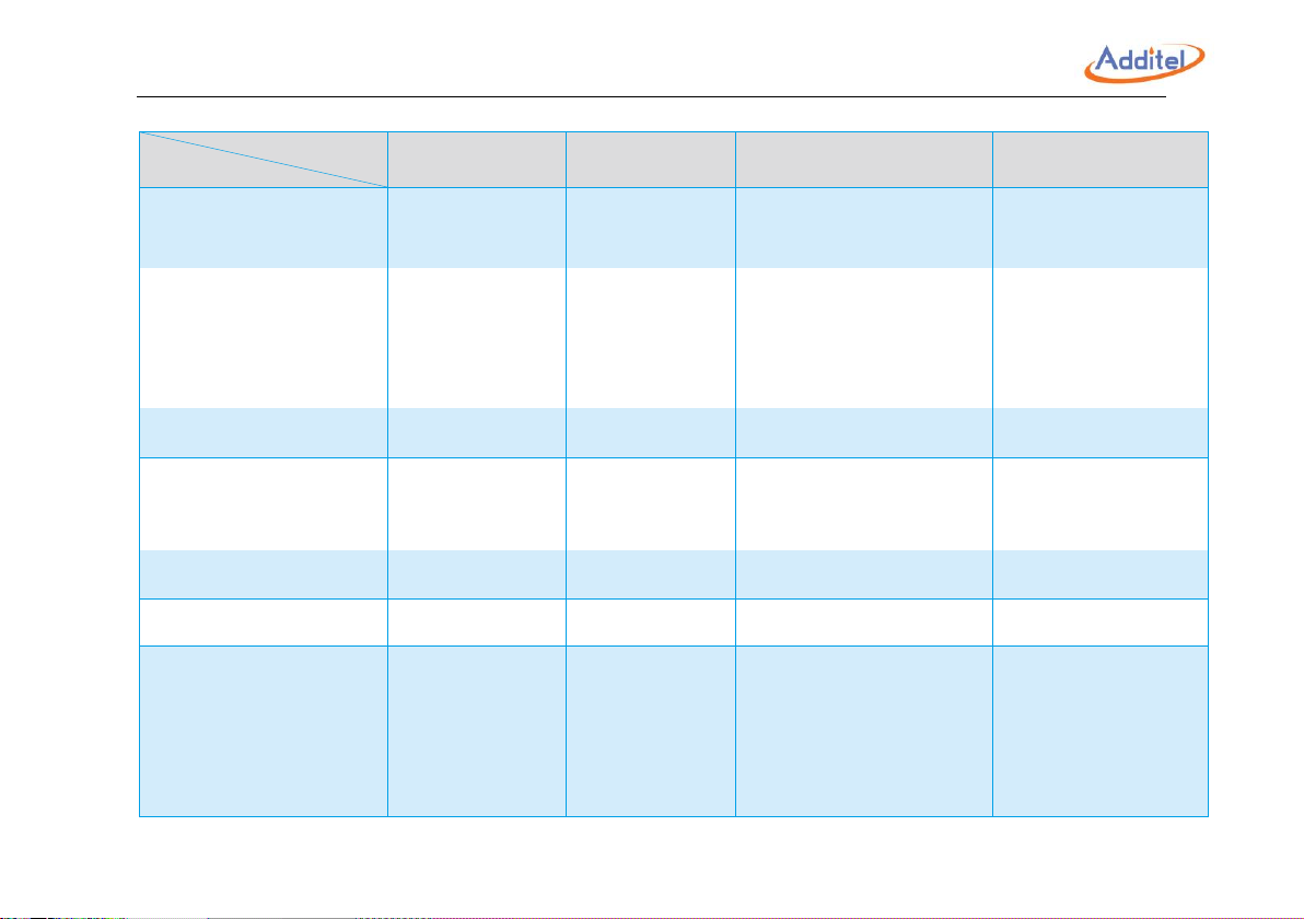
◆ Electrical measurement specification (environment temperature 20℃±5 ℃, one-year stability)
Model
Range
Resolution
Accuracy
Note
mA Measure
Auto-ranging
±25 or ±50 mA
0.1 µA
0.008%RD+0.004%FS
Impedance <10Ω
V Measure
±300 mV
1 µV
0.008%RD+0.002%FS
Impedance >1GΩ
Auto-ranging±5,
±12 or ±30 V
±5V:20 µV
±12V:100 µV
0.008%RD+0.002%FS
Impedance >1MΩ
Loop Power Source
24 V
N/A
±0.24 V
50 mA (Max Loading)
mA Source
0 to 2.5 mA or 2.5 to
25 mA
0-2.5 mA: 0.05µA
0-25 mA:0.5µA
0-2.5 mA: 0.008%RD+0.1 µA
0-25 mA: 0.008%RD+1.0 µA
20 mA @ 1KΩ
Power Source
16 to 30 V
1 V
±0.5 V(24 V: ±0.24 V)
70 mA (Max Loading)
V Source
0 to 16 V
250 µV
0.008%RD+0.002%FS
Pressure Switch
Mechanical Switch,
Live Mechanical
Switch, NPN Switch,
PNP Switch
N/A
N/A
Response time<10 ms.
If the switch is live, voltage
range will be (3-30) V
Page 19
7
Temperature Compensation
5°C to 35°C
Temperature Coefficient
Outside of 5°C to 35°C: <±0.0005%RD+0.0001%FS/°C
Misuse Protection
Up to 30 V on any two sockets
Table 1- 2 Electrical measurement specification
◆ General Specifications
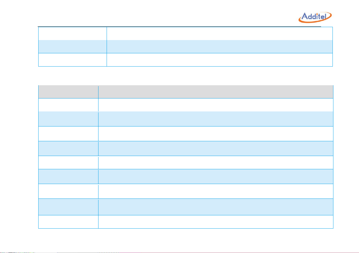
Specification
Description
User Interface
Color touch screen and/or keypad operation
Channels
Four total: one electrical, high or low internal pressure module, two external pressure modules
Enclosure IP Rating
IP31
Battery
Rechargeable Li-Ion battery, typically 16 hours of operation, recharges in less than 5 hours.
Power
Rechargeable Li-Ion battery, external power 110/220, power adapter 27 V
Display
7” TFT touch screen 800 x 480 color
Communications
USB, LAN, Bluetooth, Wi-Fi
Weight
<17.52 lb (7.95 KG)
Size
11.77 x 7.60 x 7.56 in (299 x 193 x 192 mm)
Page 20
8
Certification
ISO17025 accredited certificate of calibration with NIST-traceable data
Data Storage
6 GB
Data Logging
Up to 1,000,000 readings (data and time stamped)
Task documentation
Up to 1000 tasks can be stored with data
Automation Functions
Switch test, auto step, leak test
User Interface
Localization
English, German, French, Italian, Spanish, Portuguese, Chinese, Japanese, and Russian
Pump life
>1,000,000 cycles
Environmental
Specifications
Operating temperature: 32°F to 122°F ( 0°C to 50°C)
Compensated temperature: 32°F to 122°F ( 0°C to 50°C)
Storage temperature: -20°C to 60°C ( -4°F to 120°F)
Humidity: <90%, non-condensing
Vibration and Shock
Vibration: 4g (20 to 2,000 Hz) Shock: 8g, 1 meter drop test
Compliance
CE
Software Compatibility
ACal, Additel Land and Additel Link for access via mobile application
Page 21
9
Warranty
1 year
Table 1- 3 General Index
◆ Optional Software
ACal and Additel Land
Additel Link for access via mobile application
Page 22
10
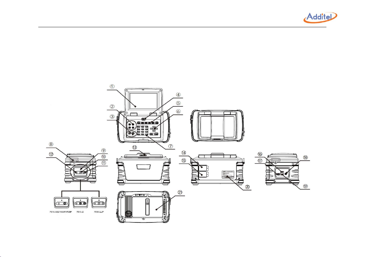
2. Installation
2.1 Features
2.1.1 Basic structure
Figure 2- 1 Basic structure
Page 23
11
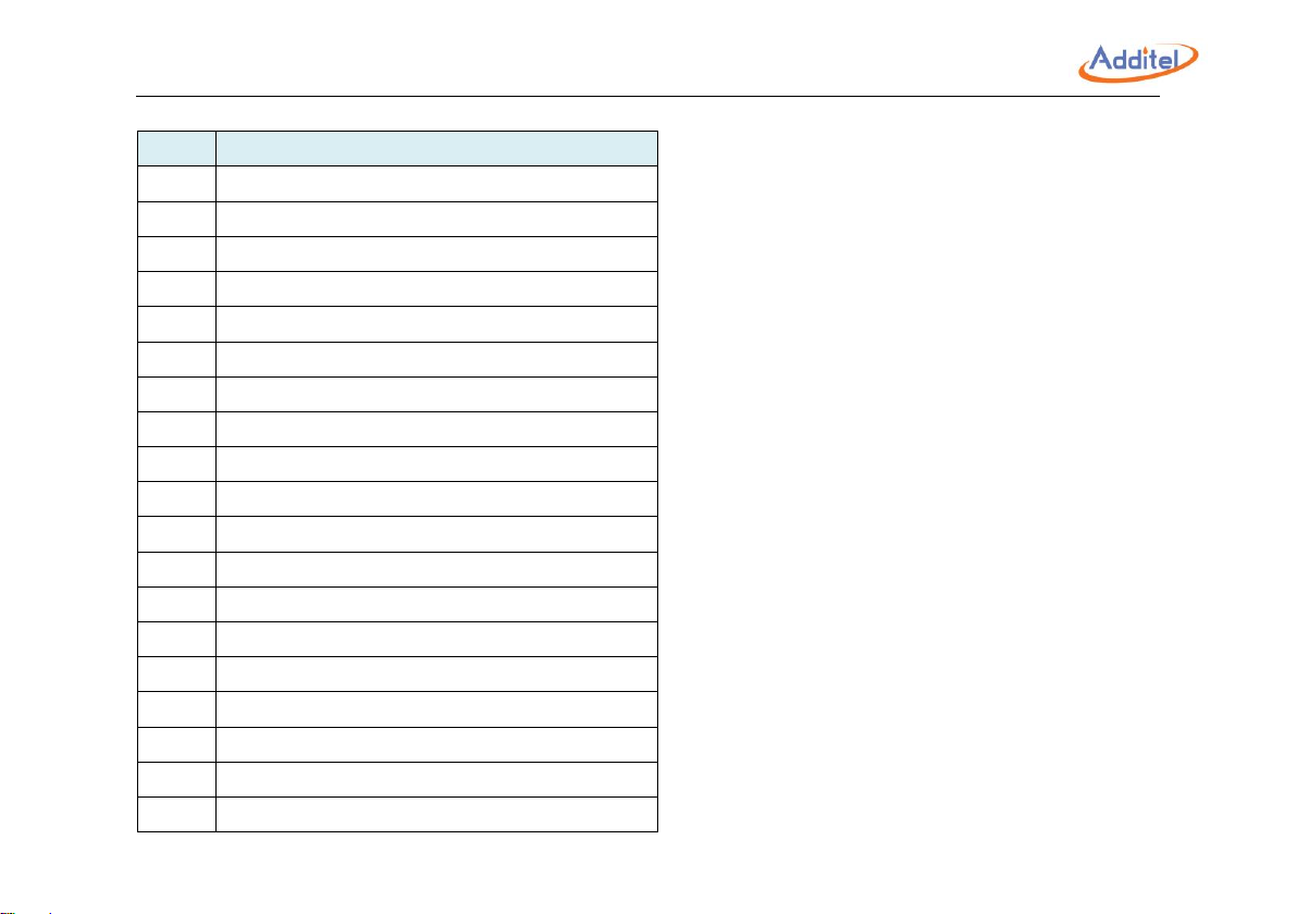
Item
Name
①
Screen
②
PC Board
③
Connector Interface
④
On/Off
⑤
Shortcut keys
⑥
Function keys
⑦
Numeric Keypad
⑧
Strap connections
⑨
Atmosphere port
⑩
REF/FLT Port
⑪
Output Port
⑫
Vent Port
⑬
Lock
⑭
High Pressure Module
⑮
Low Pressure Module
⑯
LAN Interface
⑰⑲
USB port
⑱
Power supply input
⑳
Label
Page 24
12
㉑
Battery
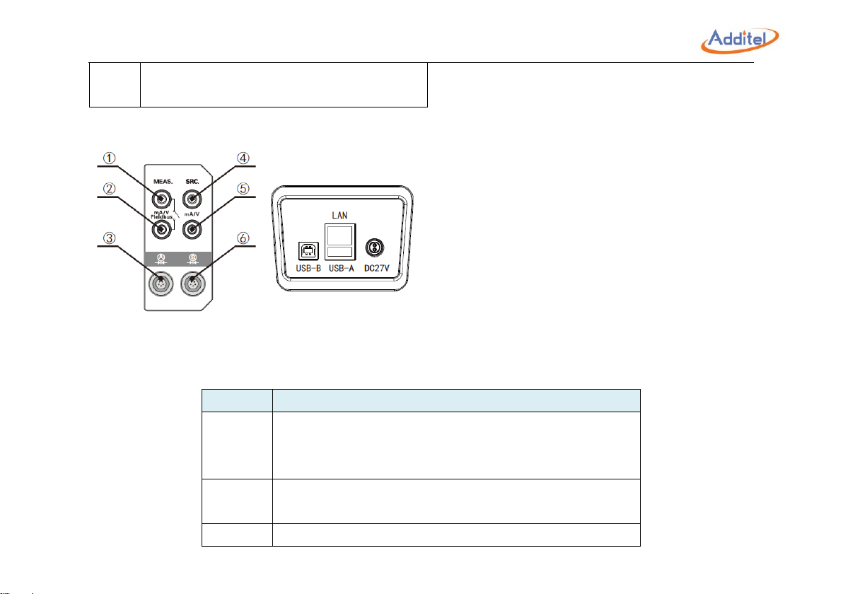
2.1.2 Electrical and signal port
Figure 2- 2 Electrical and signal port
Port
Description
①②
Current, Voltage, Switch measurement and HART,
Profibus PA bus communication, Red is positive ,
Black is negative
④⑤
Current, Voltage and power output, Red is positive ,
Black is negative
③
Jack A for connecting external pressure module
Page 25
13
⑥
Jack B for connecting external pressure module
DC27V
Power adapter connection port
LAN
Ethernet interface
USB-A
Flash drive connection
USB-B
Computer connection
Table 2- 1 Electrical and signal port
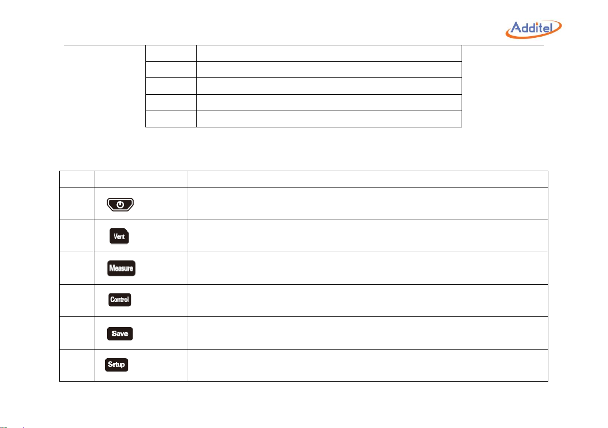
2.1.3 Keypad
Item
Keypad
Description
1 On/Off Key: Power
2 Shortcut Key: Pressure vent
3 Shortcut Key: Pressure measure
4 Shortcut Key: Control pressure
5 Shortcut Key: Snapshot
6 Shortcut Key: Setup interface
Page 26
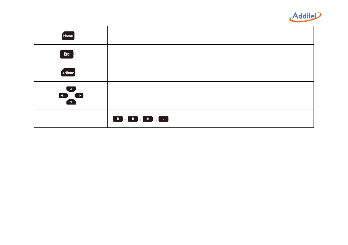
14
7 Shortcut Key: Return home
8 Shortcut Key: Cancellation or Return function
9 Shortcut Key: Fulfillment or confirmation function
10 Navigate key: Up, down, left, right key
11
Numeric Key
Table 2- 2 Keypad function
2.1.4 Pressure ports
◆Output port (OUTLEF): Pressure output port, connecting UUT. If the control volume lager than(0~100)cc, the
pressure stability will be affected.
◆Reference port (REF): If calibrator measure and calibrate the gauge pressure instruments, please keep the REF
port open. If calibrator measure and calibrator the differential pressure instruments, REF port should
be connected with reference port of UUT for isolating airflow fluctuation to obtain stable pressure
control.
◆Venting port (VENT): Venting port is used for pressure relief quickly and drain contamination. During use process, if
mist is venting out, it is recommended to collect the moisture avoiding contamination in the connected hose
Page 27

15
◆Barometric pressure calibration port (ATM): Used for calibrating the internal barometric pressure sensor. Connect to
this port by φ4 gas hose. See 4.4.4 barometric module standard in the specific operation.
2.2 Initial preparation
2.2.1 Battery installation
As shown in Figure 2-3, Open upper battery key to install or disassemble the battery in the bottom of
the calibrator.
Page 28
16
Figure 2- 3 Battery installation
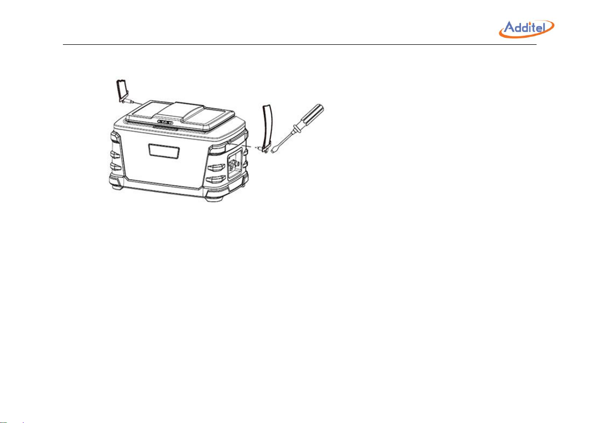
2.2.2 Changing the shoulder strap
As shown in Figure 2-4, change the Shoulder strap with a slotted screwdriver.
Page 29
17
Figure 2- 4 Changing the shoulder strap
Page 30
18
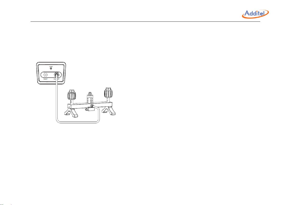
2.2.3 Pressure connection
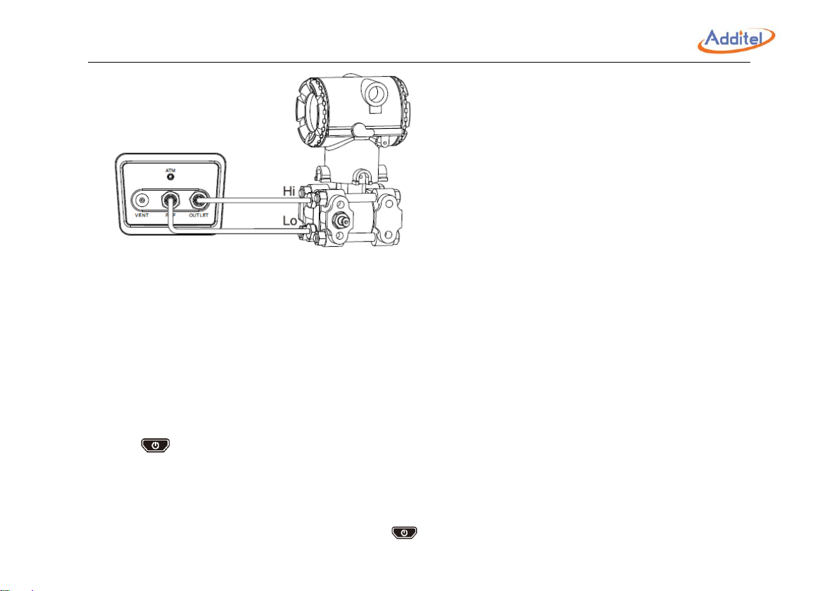
As shown in Figure 2-5, 2-6, under the situation of UUT is connected, the output port shall be sealed with the
corresponding accessories.
Figure 2- 5 Gauge pressure connection
Page 31
19
Figure 2- 6 Low pressure and differential pressure connection
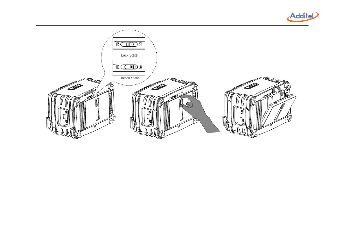
2.2.4 View the display
Push the front lock to the right and raise the screen to the proper position
2.3 Getting started
2.3.1 Power on
◆ Press to turn the power on.
◆ The startup screen shows the manufacturer's logo.
◆ After a short time the system enables the home screen.
◆ Connect the power supply for charging if power is low.
◆ If calibrator is charging, the screen will dim, press turn it on.
Page 32

20
2.3.2 Setting the system date and time
◆ Refer to section 4.6.1 to set date and time
2.3.3 Generating a pressure
At the home screen, enter the desired pressure value using the numeric keypad, press enter and calibrator will
generate and control to the target pressure (see section 3.2.1)
2.3.4 Display and operation
Touchscreen display makes operation easier, supports keypad operation, is convenient to operate and input values
quickly.
3. Display and Operation
3.1 Home screen
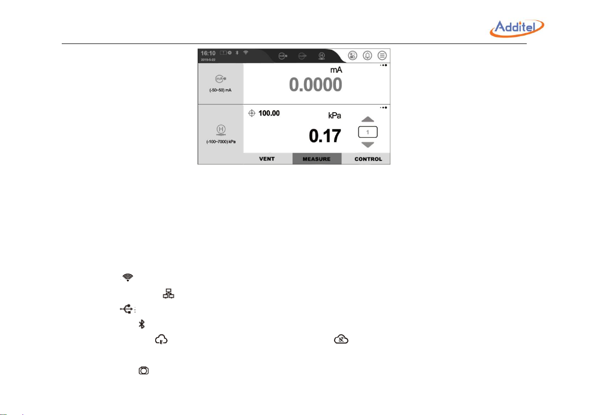
The home screen contains top status bar and module function areas, see figure 3-1 shows
Page 33
21
Figure 3- 1 home screen
3.1.1 Status bar
The status bar contains three parts, status information, module display/hidden operation and function navigation.
1. Status information display area
◆ Date and time: the time is system time
◆ Wi-Fi: Image indicates connection status and signal intensity.
◆ LAN connection: Image indicates network activity.
◆ USB: Image indicates USB device activity
◆ Bluetooth: Image indicates Bluetooth function is working.
◆ Cloud service: Image indicates cloud service is working, image indicates cloud service is enabled, but has
lost connection.
◆ Snapshot: Image indicates snapshot function is operating.
Page 34
22
2. Module function display/hidden operation area
Modules can be displayed or hidden by clicking the corresponding function icon. When the module is in the display
state, the icon is highlighted, when the module is in the hidden state, the icon is dim.
Electrical measurement module display/hidden: Icon will be displayed according to electrical measurement. When the
icon shows, it indicates the mA measurement is displayed. Click icon, then click measure function, the icon
will become dim.
Electrical output module display/hidden: Icon will be displayed according to electrical output. When electrical signal
is outputting, the arrow on the icon will be flickering.
Pressure output module display/hidden: Icon and will be displayed according to pressure control range.
External pressure module A display/hidden: Icon will be displayed when pressure module A is connected.
External pressure module B display/hidden: Icon will be displayed when pressure module B is connected.
3. Navigation function area
◆ Control center: Click icon to enter the control center. The control center has many functions, such as internal
pressure module, electrical measurement signal, electrical output signal, external module A, external module B,
positive pressure air source and negative pressure air source, lock screen function, Bluetooth communication and
Wi-Fi communication open and close and so on.
◆ Notification center: when exceptions happen, The icon will turn to red and highlight. Click the icon to know more
information about the exception.
◆ Main menu: Click icon , the main menu provides system configuration, HART communicator, quick test, task and
application functions and so on.
Page 35
23
3.1.2 Module and split screen display area
The module function display area is divided into electrical signal measuring area, electrical signal output area, external
pressure module A and B (once pressure modules are inserted). By clicking "Module function display/hidden operation
area" in the status bar, above functions display areas can show and hidden, at the same time, module function can set
screens' quantity from one to five.
◆ Pressure output area: see section 3.2 pressure output.
◆ Electrical signal measuring area: see section 3.3 electrical signal measuring .
◆ Electrical signal output area: see section 3.4 electrical signal output.
◆ External pressure module A & B areas: see section 3.5
3.1.3 Main interface keypad operation
◆ By click and on main interface , you can choose each function area icon, showing orange frame.
Press to trigger corresponding function, press to quit corresponding function.
◆ Press to type targeted value in pressure output area , then press to generate and
control to that pressure. Press to adjust targeted value. If the pressure output is hidden and the electrical
signal output area is displayed, press and enter to electrical output area or press to adjust electrical
output value.
Page 36
24
3.2 Pressure control
3.2.1 Pressure output
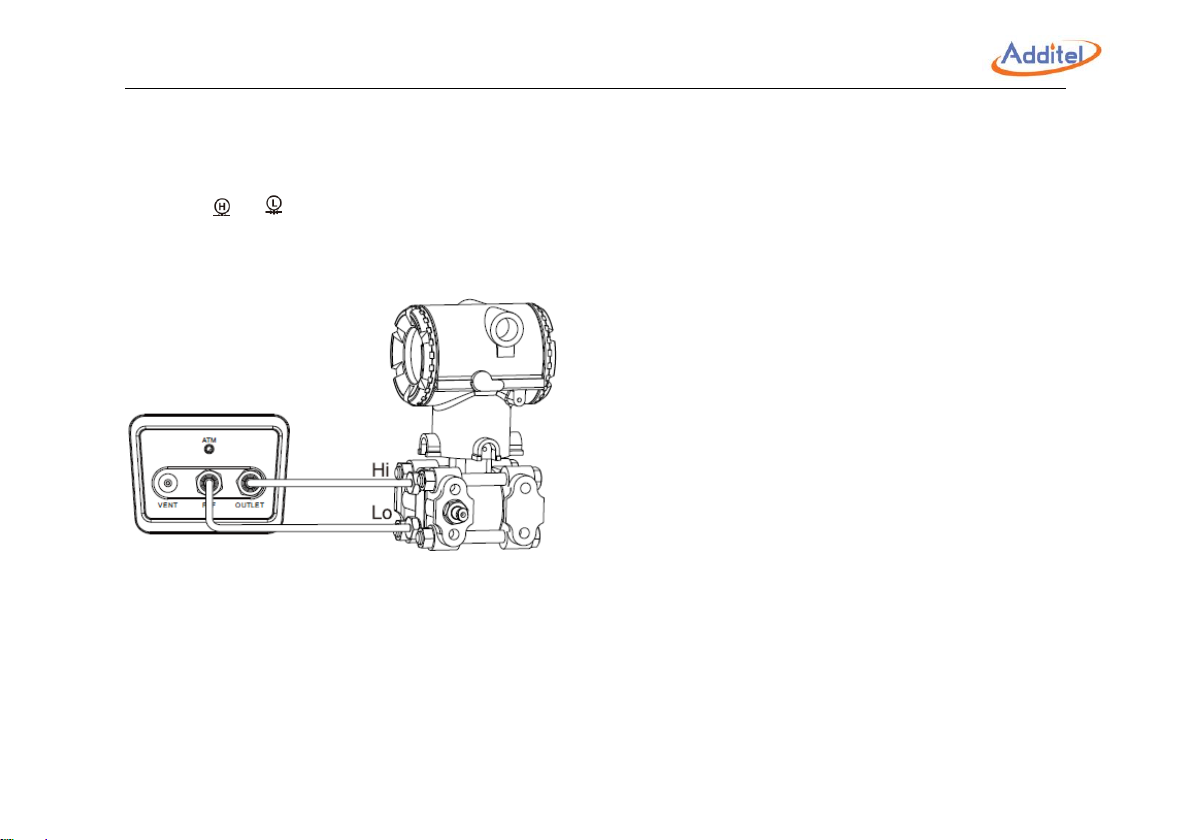
1. Click or to open internal pressure control on status bar: High pressure range and low pressure range.
◆ Click on the high or low pressure icon on the left status bar to switch the internal pressure module.
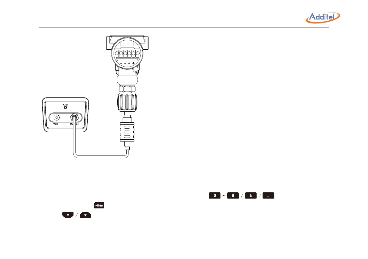
2.Connection: See figure 3-2 and 3-3 as shown:
Figure 3- 2 Differential pressure outlet
Page 37
25
Figure 3- 3 Gauge pressure outlet
3. Input target value
◆ Pressure output area, touch screen to enter value or press button on the main
interface , then press for confirmation.
◆ Press to increase or decrease the pressure target by the predetermined step size.
◆ ◆ The maximum negative pressure depends on current barometric pressure and the ability of the internal pump to
generate this pressure. Meanwhile, the maximum pressure value depends on the control setting configuration (see
Page 38
26
section 4.1). If the target pressure exceeds the limit, then the calibrator will error and allow for another pressure to be
entered.
◆ When target pressure exceeds current pressure range of the internal module but is within the range of the
second internal module, it will switch to the applicable module.
4. Start /stop controlling pressure
◆ The Calibrator will start controlling after the target pressure value is achieved.
◆ On the status of vent or measure, click or “control” button on the screen to start controlling to the target
pressure.
◆ Press or click “vent” and “measure” button on the screen to stop control.
5. Pressure stability
◆ When stable within the control settings, the displayed pressure value will change from white to green.
6. Auto step
◆ Press to enter into auto step setting interface, see parameter in figure 3-1:
Item
Effective value
Description
Stroke
Round trip or one way
Setting travel mode of auto step
Loop time
0-100
Setting loop time of auto step
Step mode
Step point, percent, unit, default
Incrementing mode of auto step
Cycle interval
0-3600 seconds
Stop time between every cycle end and the next cycle start
Dwell time
0-3600 seconds
The time is pressure stable at each step
Page 39
27
Step quantity
2-17
The number of steps
Range
Range will be based on the largest
range internal module
Setting auto step output range
Point list
Point list is read only except when
“Custom” is selected for Step
mode
Shows the pressure points of the auto step routine
Table 3- 1 setting interface
7. Manual step
◆ Press or click on screen to achieve pressure output manual step.
◆ Click the middle number on icon to set up manual step value. The icon will be present when the split screen
display shows only one or two fields.
3.2.2 Pressure measurement
1. Open internal pressure control item to switch pressure measurement: High or Low pressure range
◆ When changing internal module ranges the calibrator will open to atmosphere and then change ranges
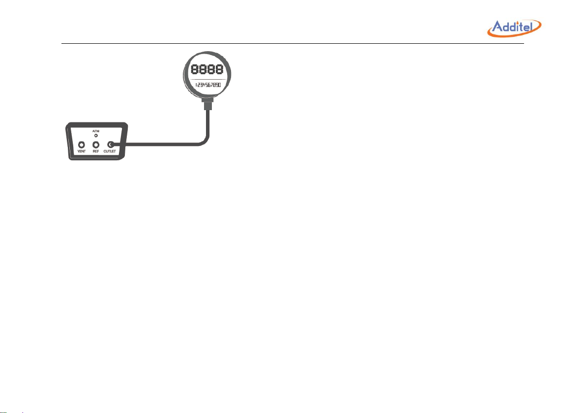
2: Connection: figure 3-4
Page 40
28
Figure 3- 4 Pressure Measurement
3: External pressurization
◆ Do not pressurize the calibrator beyond the measuring module range.
◆ When external pressure exceeds the current range, the value turns red and alarms at the same time.
◆ If the external pressure exceeds the maximum range, the system will immediately vent .
3.2.3 Pressure unit
◆ When the item of pressure output, pressure measurement or external pressure module is selected, click the
pressure unit area on the screen to select a the desired unit.
3.3 Electrical signal measurement
The electrical signal measurement area provides such functions as current measurement, voltage measurement,
Page 41
29
switch testing, HART communication and Profibus PA communication. Click the item icon and range at the left
measurement area to switch the electrical measurement.
3.3.1 Current/Voltage measurement
1. Click the input icon or on the status bar to display the electrical measurement. Click
the range area on the screen to switch the electrical measurement or range.
Do not apply current/voltage outside the calibrator’s range.
Short-circuit zeroing is allowed.
If the measured value exceeds the present range, it will turn red and give an alarm.
If the measured value exceeds the measurable range of calibrator, it will display red "--------"
and give an alarm.
2. Connection: Connect the electric circuit as shown in Figures 3-5 and 3-6.
Page 42
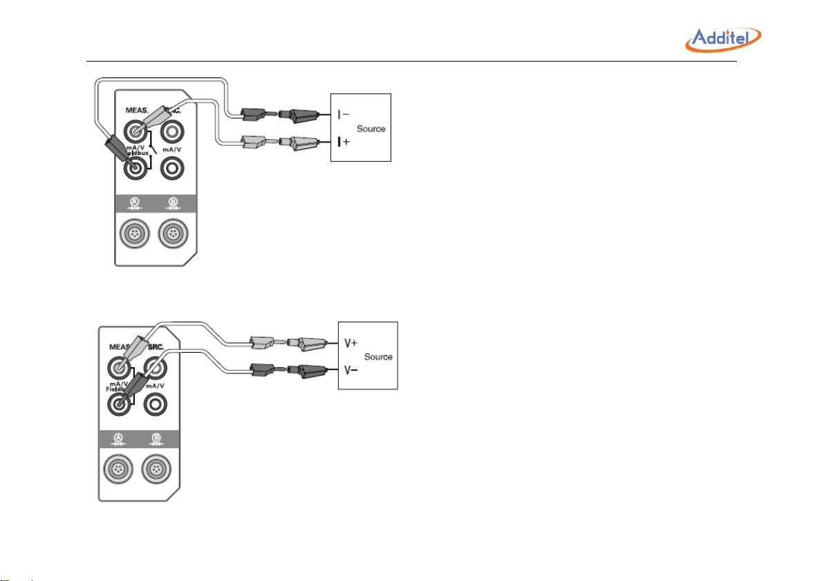
30
Figure 3- 5 Current measurement
Figure 3- 6 Voltage measurement
Page 43
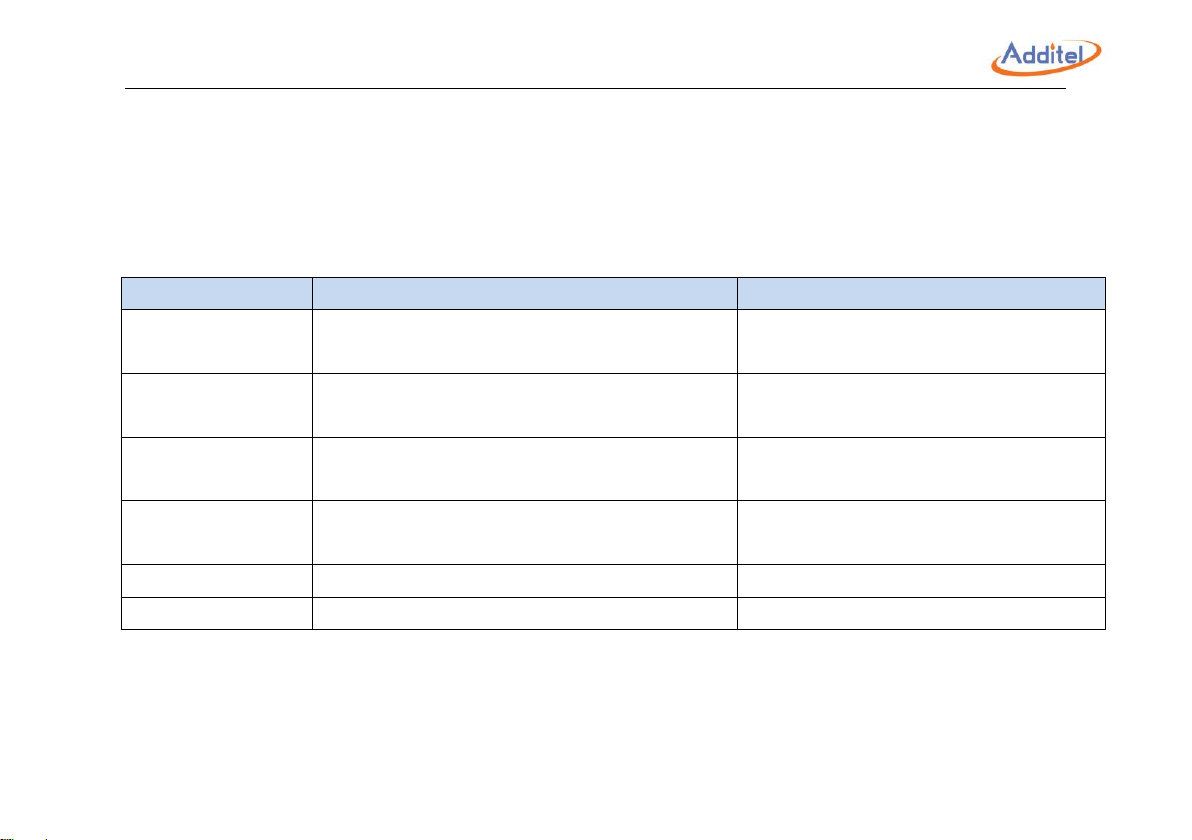
31
3. Functional operation
Zeroing: Zero the measurement to eliminate drift. The allowable zeroing range is 1%FS.
Scaling: Converts the current/voltage signal into pressure signal for display.
Item
Effective value
Description
Transfer function
Linear, square root, square
Type of the conversion function of the
scaled value
Input range
0%~100%
Percentage of the input range of
scaling
Unit
Depend on the electrical measurement
selected
Input unit of scaling
Output range
0%~100%
Percentage of the output range of
scaling
Unit
User-editable field.
Output unit of scaling
Resolution
1, 0.1, 0.01, 0.001
Resolution of scaling
Table 3- 2 Scaling parameters
Filter: Provides a first order linear filter and a moving average filter. The moving average filter
also allows setting the extremum pair.
Page 44
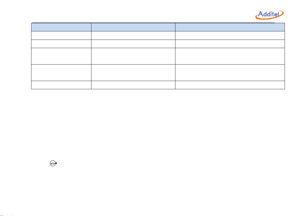
32
Item
Effective value
Description
Filter type
First-order filter and average filter
Select the filtering mode.
Coefficient
0.01~1
Applicable to the first-order filter.
Filter sampling number
Integer 1~100
Sampling number of the average filter,
correlated with the sampling time.
Filter sampling time
0~20sec
Sampling time of the average filter,
correlated with the sampling number.
Extremum pair number
Integer 0~10
Extremum pair number of the average filter
Table3- 3 Filtering parameters
Resolution: Allows setting digit resolution.
Stability: Allows setting the stability of measurement data.
Loop power supply: Applicable only for the current measurement. Select enabling/disabling
loop power supply.
3.3.2 Switch test
1. Similar to 3.3.1, open the electrical measurement options, click the range area on the screen, and
select for switch test. The calibrator can test three types of switches, i.e. mechanical switch,
NPN electronic switch and PNP electronic switch.
2. Connection
If mechanical switch is selected, connect the electric circuit as shown in Figure 3-7.
Page 45
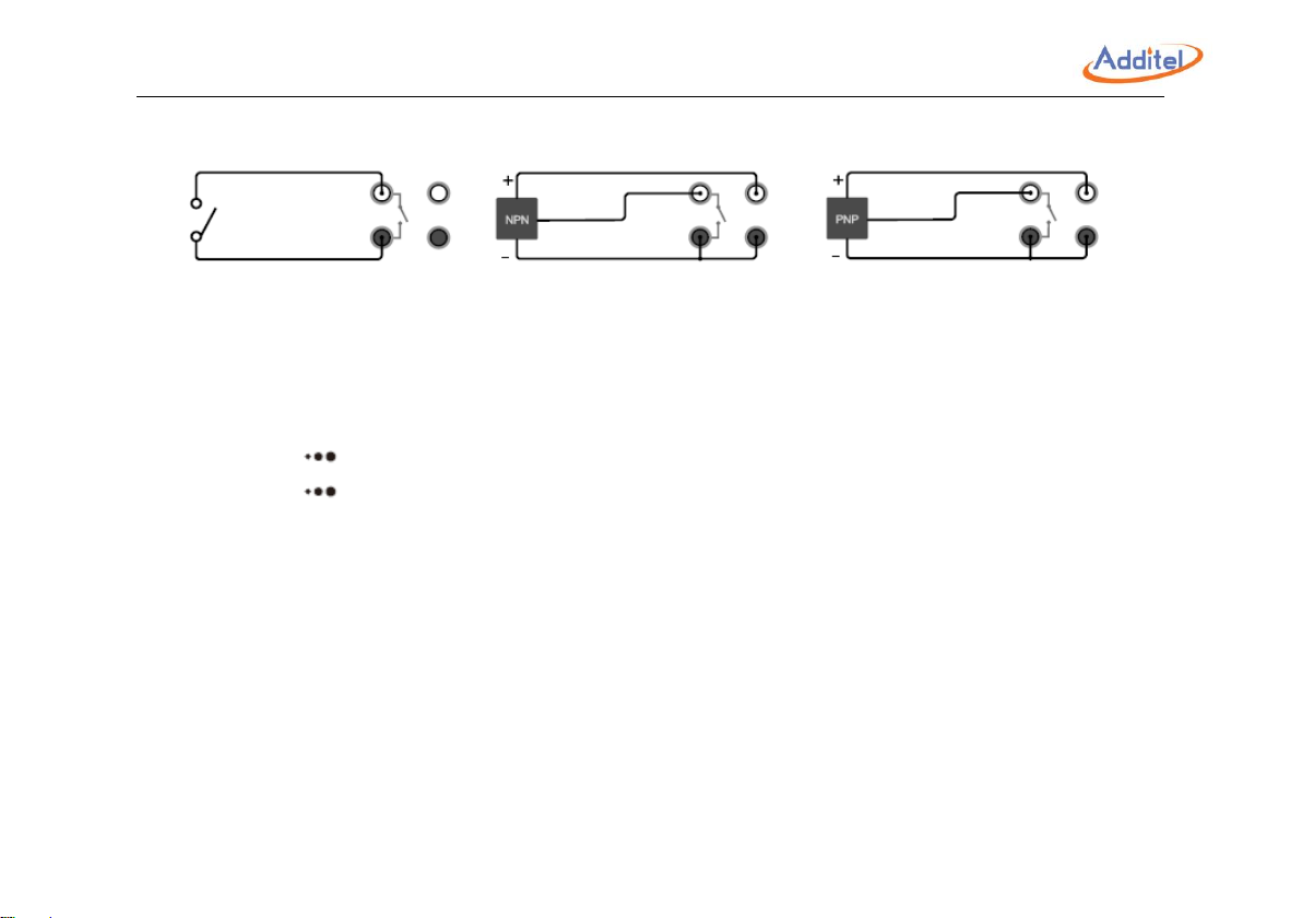
33
If NPN electronic switch is selected, connect the electric circuit as shown in Figure 3-7.
If PNP electronic switch is selected, connect the electric circuit as shown in Figure 3-7
Figure 3- 7 Switch testing
The switch action values are recorded only when the output item is pressure.
Only a pair of action values is recorded, including the switch state (on to off/off to on) when
triggered and pressure value.
Press and select "Reset", to clear the action values.
Press and select "Switch Setup", to switch between mechanical switch, NPN switch
and PNP switch.
3.3.3 HART Communication
The calibrator supports HART bus communication, uses simplified DD files, and provides setting
maintenance and calibration for general and common parameters of HART pressure transmitters.
Before using the calibrator to operate the transmitter, please refer to the user manual of transmitter. If
you need full-featured HART operation, please refer to Chapter VII "HART communicator".
Note: During communication with a HART device, the calibrator acts as a master station all the time.
To avoid damaging the control system, you must separate the HART device from the control system
before connecting the calibrator to HART device.
Page 46
34
1. Search and connection
Under the main operation interface, open the electrical measurement area for display. Select
in mode switching to enable the HART function. The calibrator will automatically switch to power
configuration selected previously (connection mode of internal power supply and internal resistance
by default), and search for the address "0". When a HART device is found, the calibrator will
automatically connect to it and display its reading.
Press and select "Search", or click the HART measurement channel screen when no
HART device is connected, to enter the HART power configuration interface. The calibrator provides
the following connection mode:
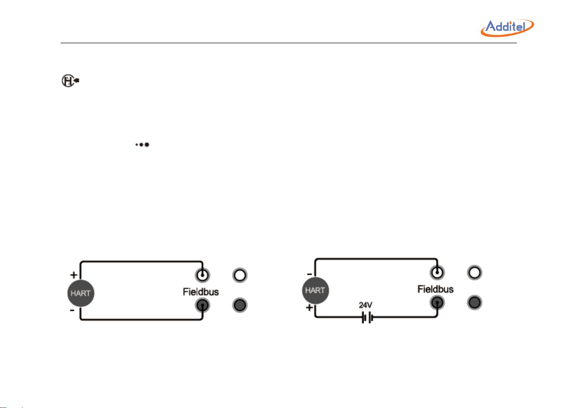
1) For the connection mode with internal power supply and internal resistance, see Figure 3-8.
2) For the connection mode with external power supply and internal resistance, see Figure 3-8.
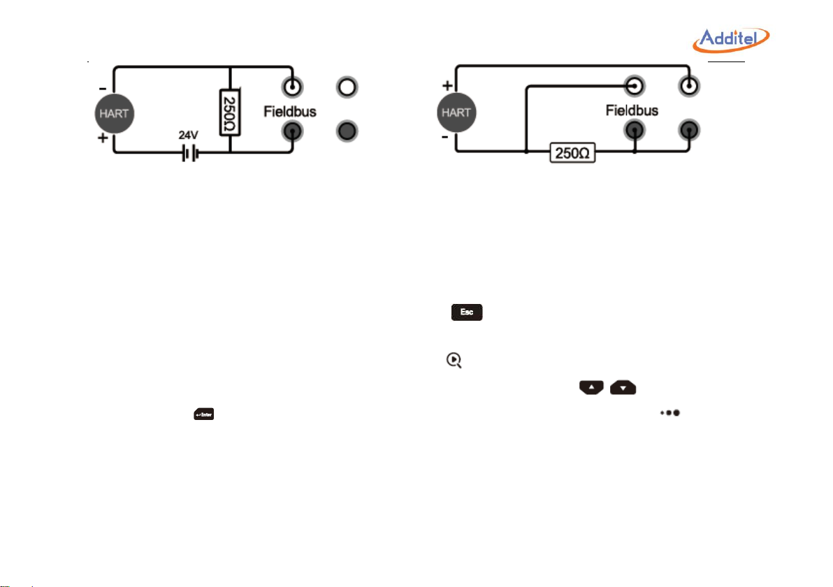
3) For the connection mode with external power supply and external resistance, see Figure 3-9.
4) For the connection mode with internal power supply and external resistance, see Figure 3-9.
Figure 3- 8 HART connection
Page 47
35
Figure 3- 9 HART connection
After the power supply configuration is selected, you will enter the search interface. Start
searching HART devices from the address "0". If successful the connection will be made and the
HART device will be displayed. If no connection is established the calibrator will continue to search
from the address "1" until "15". After the search is complete, the calibrator will list all the HART
devices found, and can support at most 15 HART devices at the same time.
During the search process, you can press the key to stop searching and return to the
power configuration interface.
After searching is finished, you can press the key to conduct a new search.
After searching is finished, if any HART device is online, press the / key to select it,
then press the key to confirm establishing connection with this device; press the key and
select "Setup" to read main information of the selected device.
2. Online/offline
After connection is established, HART will be displayed as electrical measurement item on
the main interface.
Under the main interface, when electrical measurement is switched to other measurement
Page 48
36
mode (e.g. current measurement), it will exit HART connection. Meanwhile, the HART measurement
icon in the status bar will change to a corresponding icon (e.g. current measurement).
Under the main interface, if HART communication fails, it will automatically search new
devices again.
During a test with HART, the test will give a prompt if the HART is offline.
3. Process quantities
On the main interface, HART acts as an electrical measurement item. Press to enter
process quantities. It can display the primary variable PV, output current A0, percentage, second
variable, third variable and loop current at the same time, in which the units of second variable and
third variable are determined by different devices.
In the process quantity menu, press the / key or click the screen to select, and then
press the or key for confirmation, so as to switch primary and secondary display.
During task calibration of a HART transmitter, you shall first select the HART process
quantity to be calibrated.
4. Setup
(1) Parameters
Under the main interface, switch to HART electrical measurement. Press to enter setup.
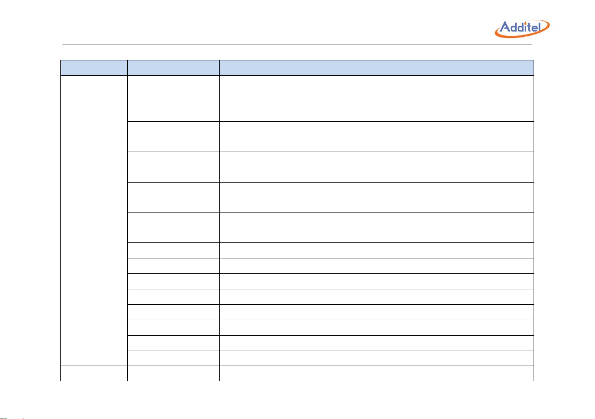
Then, you can view and set HART parameters. See Table 3-4.
Page 49
37
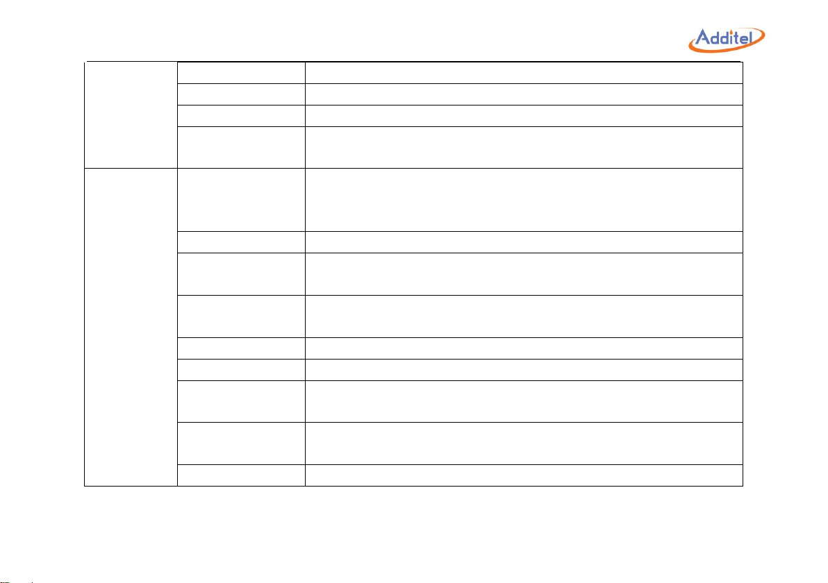
Item
Parameter
Description and effective value
Device
information
Label
Support input of letters, numbers and symbols, no longer than 8
characters.
Device
information
Date
It can be modified to any date supported by the transmitter.
Information
Support input of letters, numbers and symbols, no longer than 32
characters.
Description
Support input of letters, numbers and symbols, no longer than 16
characters.
Final assembly
number
Support input of integers, no longer than 8 digits.
Pilot symbol
number
Support input of integers from 5 to 20.
Manufacturer
Read-only parameter
Device type
Read-only parameter
Device number
Read-only parameter
Write protection
Read-only parameter
Common version
Read-only parameter
Software version
Read-only parameter
Hardware version
Read-only parameter
Device version
Read-only parameter
Sensor
Sensor S/N
Read-only parameter
Page 50
38
Sensor unit
Read-only parameter
Lower sensor limit
Read-only parameter
Upper sensor limit
Read-only parameter
Minimum sensor
range
Read-only parameter
Device output
Primary
variable/range unit
It can be modified to any unit supported by the transmitter. During
modification, the upper and lower limits are displayed through
conversion.
Pv lower range limit
Not exceed the lower sensor limit.
Pv upper range
limit
Not exceed the upper sensor limit.
Conversion
function
It can be modified to linear or square root.
Damping
Device data filtering time, in the unit of S
Polling address
0 by default, support input of integers from 0 to 15.
Emergency mode
It can be set to Enable/Disable, depending on whether the transmitter
supports it or not.
Emergency
command
The emergency command value can be set.
Alarm state
Read-only parameter
Table 3- 4 Hart Parameters
Page 51
39
2) Operation
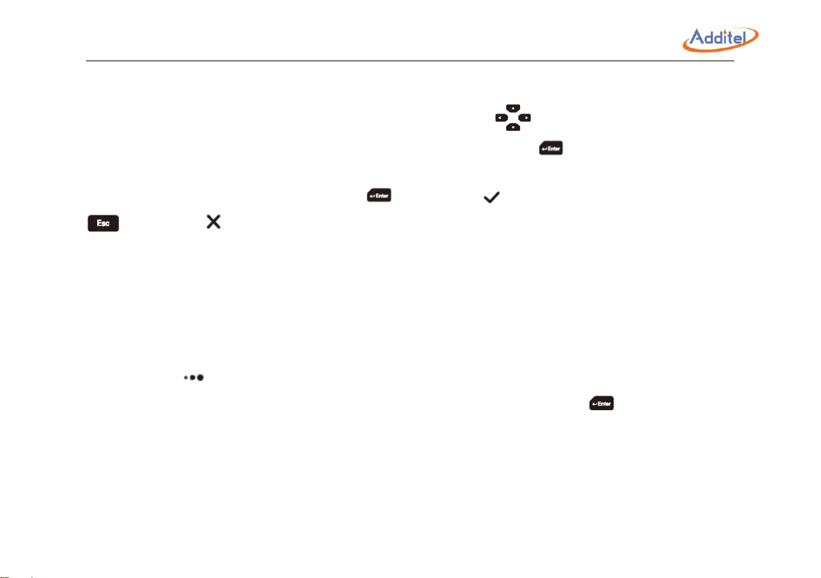
Under the HART setup interface, you can press the key to view HART parameter
values in real time; select a parameter that can be set, then press the key or click the screen to
enter the set state.
After input is complete, press the key or click on the screen to save it; press the
key or click on the screen to cancel saving and return.
If the input value is displayed in red when saving, it indicates that the input value is invalid.
Please check its input range.
If the present setting is cancelled or setup fails, the present item will be resumed.
5. Maintenance
1) Current loop test
Click and select "Diagnosis/Service", to enter current loop testing. Use number keys to
input or press the right side to select a test current value. Then press the key to perform a
current loop test. The value range of this parameter is 4-20 mA.
The HART measured value at the left bottom of calibrator interface is the real value of
current loop.
2) Primary variable zeroing
Select "Zero" on the HART diagnosis/maintenance interface. Then select a pressure module
Page 52
40
to enter the zeroing interface.
Ensure that the present measured value adequately approaches zero; otherwise, it may
cause zeroing to fail.
3) Current regulation
Adjust the proportion of current output of the transmitter, to make its AO value consistent with
the actually output loop current.
Provide regulation of the D/A zero (4mA) and D/A gain (20mA). You can press the screen to
acquire the present value, and press the key to perform regulation.
4) Sensor trim
Sensor trim is to adjust the PV process variable of the transmitter, generally including one or two
trim points (lower point and upper point). Some transmitters do not support the sensor trim operation
(as for whether the transmitter supports sensor trim, please refer to the user manual of transmitter).
Lower trim
Support setting the PV unit and trim point value. You can select two pressurization methods,
internal and external pressurization. Press the key to enter the execution interface.
Note: External pressurization requires an external pressure module.
1) Internal pressurization: Select high-pressure and low-pressure modules, to automatically
output the pressure of the trim points. Wait for the pressure to stabilize and press the "Get" key to
directly acquire the value, or manually enter the trim values.
2) External pressurization: Manually control the pressure of transmitter through an external
source. Wait for the pressure to stabilize and press the "Get" key to directly acquire the value, or
manually enter the trim values.
Page 53

41
Note: Some transmitters may not allow selectable trim values, and automatically use the upper
and lower range limits as trim values (the lower range limit corresponds to the lower-point trim value,
and the upper range limit corresponds to the high-point trim value). In this case, you can input any
value.
3) Execute the adjustment (Trim) command. After completed successfully, the PV value will
change with the executed trim point value.
Upper trim
The operation procedure of upper trim is the same as that of lower trim.
Factory reset
Select "Factory Reset", then a prompt will ask "Are you sure to restore factory settings of the
sensor?" Press the key or click on the screen to execute the factory reset command. After
completed successfully, the upper and lower trim values will restore factory settings.
3.3.4 PROFIBUS PA communication
The calibrator supports PROFIBUS PA bus communication. It can set and calibrate the parameters of
PROFIBUS PA pressure transmitter (PA transmitter). Before conducting any operation to the PA
transmitter, you shall understand relevant terms of PROFIBUS PA protocol such as Physical Block,
Transducer Block, Function Block, TARGET_MODE, AUTO, OSS and Man. Before use, please refer
to the user manual of transmitter.
Note: During communication with a PA transmitter, the calibrator acts as a master station all the time.
To avoid damaging the control system, you must separate the PA transmitter from the control system
Page 54

42
before connecting the calibrator to PA transmitter.
1. Device description file
The device description file is used to describe device parameters and parameter access modes.
Through the parameter description information, you can view and set related parameters of the PA
transmitter. The calibrator uses specific device description files, to access main parameters in the
Physical Block, Transducer Block and Function Block of PA transmitter. This calibrator includes
device description files of common mainstream PA pressure transmitters. If you need to add new
device description files of transmitter, please contact us.
2. Connection and search
For the connection mode, please refer to Figure 3-10.
Click the icon to start searching; and click the icon to stop searching.
From the searched PA device list, click a PA device to be connected. After connection is
successful, return to the main interface.
3. Process quantities
Click , then a function menu will pop up. Select "Process Quantity" in the function menu. The
calibrator provides switching between display of process quantities such as PRIMARY_VALUE,
SENSOR_VALUE, SECONDARY_VALUE_1, TRIMMED_VALUE, SECONDARY_VALUE_2 and
STATIC_PRESSURE_VALUE.
4. Transmitter operation
(1) Setup
After clicking , a function menu will pop up. Select "Setup" in the function menu to enter
the setup interface.
Page 55

43
On the setup interface, you can access and set parameters in the Physical Block,
Transducer Block and Function Block.
Before modification of some parameters, you may need to modify corresponding
TARGET_MODE (e.g. set it to OOS, Auto, Man, and so forth). Specifically, you can follow the user
manual of PA transmitter to modify related parameters.
(2) Calibration
Click , then a function menu will pop up. Select "Calibrate" in the function menu to enter
the calibration interface.
You can calibrate the PA transmitter on the calibration interface. Before performing
calibration on the PA transmitter, please refer to relevant description of adjustment (Trim) part in
the user manual of PA transmitter.
3.4 Electrical output
You can click a corresponding electrical output icon in the module display/hide operation area on the
top status bar, to display/hide the electrical signal output module. When the electrical output is
displayed, the corresponding icon on the status bar will be highlighted. When the electrical output is
hidden, the corresponding icon will be dim and when signals are output, the output arrow on the icon
will flicker.
1. Changing the range
Click the range area on the left side of the measurement area to switch the output item. The calibrator
supports 0~25mA, 0~16V and 16~30V power output.
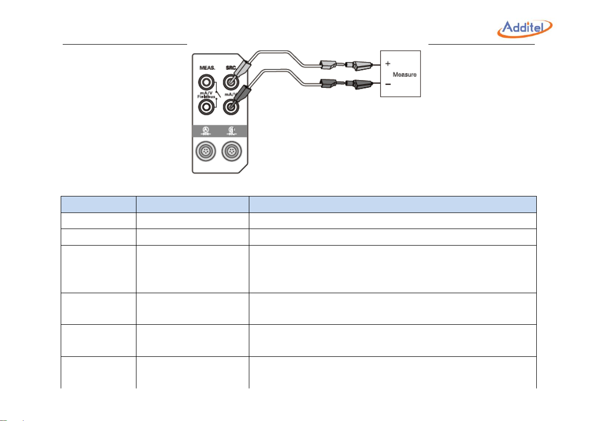
2. Connection: Connect the electric circuit as shown in Figure 3-14.
Page 56
44
3. Enabling loop power (for current supply only)
According to the connection mode, press the key and select whether to enable loop
power.
Power will be supplied as soon as loop power is enabled.
4. Input of the target set value
When the pressure output module is hidden, press the key to enter the setup interface
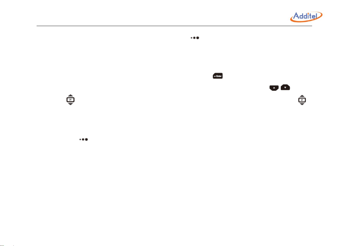
of electrical output values; when the pressure output module is hidden, press the / key or
press the key on the screen to realize step output of current, and set the step value inside .
The set value shall meet the calibrator's current output range of 0~25mA, voltage output
range of 0~16V, and power output range of 16~30V.
5. Auto step
Press the key to enter the auto step setup. For the auto step parameters, see Table 3-5.
Page 57
45
Figure 3- 10 Current output of internal power supply
Item
Effective value
Description
Stroke
Round trip or one way
Set the trip pattern of auto step.
Cycle number
0-100
Set the cycle number of auto step.
Step mode
Step point,
percentage, value, or
custom
Set the mode of automation step.
Cycle interval
0~3600 sec
Standing time between the end of each cycle and the start of
next cycle.
Dwell time
0~3600 sec
Standing time after the present electrical output becomes
stable.
Step point
number
2-17
It can be set when the step mode is step point.
Page 58
46
Range
Not to exceed the
electrical output range.
Set the output range of automatic step.
Step point list
Editable when the step
mode is custom;
read-only and
displayed under other
modes.
Display the set point list of automatic step.
Step value
6.25%" 00%
It can be set when the step mode is percentage.
Step value
1.5625~25mA
It can be set when the step mode is value.
Table 3- 5 auto step parameters
6. Manual step
Press the / key on the keyboard or on the screen, to manually step through
values.
You can click the number inside to set the step value of manual step.
7. Ramp
Press the key to enter the Ramp setup interface (only 0~25mA and 0~16V is applicable).
For the Ramp output parameters, see Table 3-6.
Item
Effective value
Description
Range
Do not exceed the electrical output
range
Set the ramp output range.
Page 59
47
Rise time
4~60 sec
Ramp rise time
Fall time
4~60 sec
Ramp fall time
0% wait time
1~60 sec
Wait time of the slope at the lower range value.
100% wait time
4~60 sec
Wait time of the slope at the upper range value.
Repeat
0-100
Set the cycle number of slope. 0 indicates infinite
repetition.
Table 3- 6 Ramp parameters
3.5 External pressure module
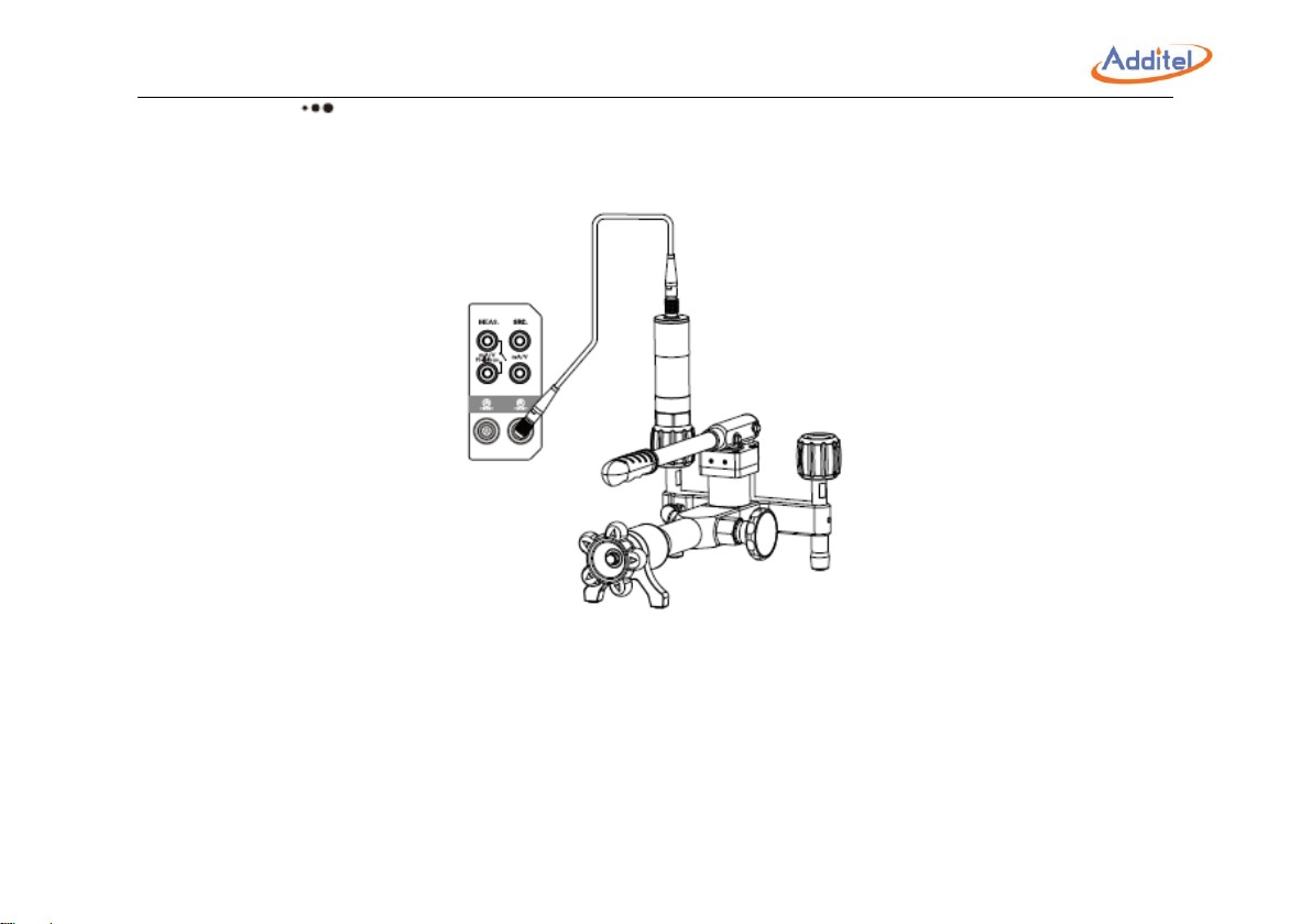
1. Connection: Connect the external pressure module as shown in Figure 3-11.
2. Display of the external pressure module
When the pressure module is connected properly, the status bar will display the online icon
of pressure module. The calibrator supports two external pressure modules A and B, and provides
multi-screen display with other parameters. When the external pressure modules A and B are both
connected, the calibrator can show up to five items in the multi-screen.
If the measured value exceeds the present range of pressure module, it will turn red and give
an alarm.
If the measured value exceeds the measurable range of pressure module, it will display red
"--------" and give an alarm.
3. Related operations of external pressure module
The pressure unit can be switched.
The atmospheric pressure version can switch the pressure type.
Page 60
48
Press to invoke the function menu. Select "Measurement Stability", to set the stability
time and degree.
Zeroing is allowed.
Figure 3- 11 Connection of the external module
Select "Module Information", to view related information of the external pressure module.
Select "Resolution", and set the number of digits displayed to 4, 5 or 6.
Select "Filter". Then, you can select first-order filter or average filter as the filter type, and set
related parameters.
Page 61

49
3.6 Typical applications
3.6.1 Pressure gauge
1. Prepare
Open the pressure output area of main operation interface: High-pressure or low-pressure
range (depend on the range of calibrated instrument).
2. Connection
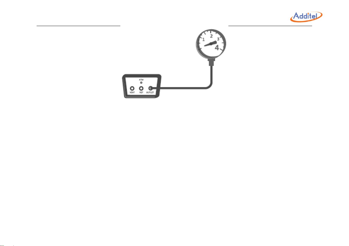
Connect the gauge as shown in Figure 3-12.
When the calibrated instrument is a differential pressure gauge, connect the REF port
properly. For the connection mode, see Figure 3-2 Differential pressure output.
3.
Manually set or use the step function (see Section 3.2.1 "Auto step and manual step of pressure
output") to output the pressure of each calibration point.
Page 62
50
Figure 3- 12 Calibration of a pressure gauge
4. When the pressure of each calibration point becomes stable and is displayed in green, record the
readings of each point.
3.6.2 Pressure transmitter
The calibrator supports calibration of 2-wire, 3-wire and 4-wire pressure transmitters.
1. Prepare
Open the pressure output area of main operation interface: High-pressure or low-pressure
range (depends on the range of the transmitter).
Switch the electrical measurement item of main operation interface to: Current or voltage
measurement (depend on the output signal of the transmitter).
Page 63
51
If the current-type 2-wire pressure transmitter needs loop power supply, you shall enable
loop power supply in the current function menu.
2. Connection
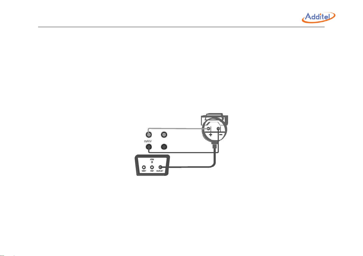
For a 2-wire pressure transmitter connect as shown in Figure 3-13.
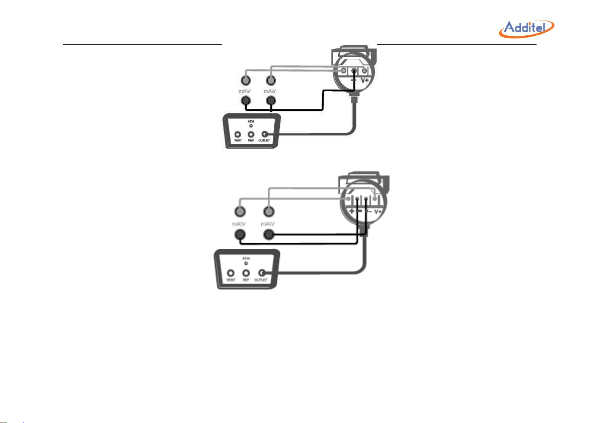
For a 3-wire pressure transmitter, connect as shown in Figure 3-14.
For a 4-wire pressure transmitter, connect as shown in Figure 3-15.
If the transmitter is a differential pressure transmitter, you shall connect the REF port
properly.
Figure 3- 13 Calibration of a 2-wire pressure transmitter
Page 64
52
Figure 3- 14 Calibration of a 3-wire pressure transmitter
Figure 3- 15 Calibration of a 4-wire pressure transmitter
3. Manually set or use the step function (see Section 3.2.1 "Auto step and manual step of pressure
output") to output the pressure of each calibration point.
4. When the pressure of each calibration point becomes stable and is displayed in green, record the
output value of the transmitter at each point, or use the snapshot feature.
Page 65

53
3.6.3 HART transmitter
1. Prepare
Open the pressure output area of main operation interface: High-pressure or low-pressure
range (depends on the range of the transmitter).
Switch the electrical measurement item of main operation interface to: Current measurement
2. Connection
Connect the transmitter as shown in Figure 3-17; connect the electric circuit as shown in
Figure 3-10, 3-11, 3-12 or 3-13.
3. Establish connection (see Section 3.3.1). During setup, switch the process quantity to current
output.
4. Press the setup icon, to set the parameters of the HART transmitter (see Section 3.3.3).
5. Press the setup icon, to maintain the process quantities of the HART transmitter (see Section
3.3.3).
6.
Manually set or use the step function (see Section 3.2.1 "Auto step and manual step of pressure
output") to output the pressure of each calibration point.
7. When the pressure of each calibration point becomes stable and is displayed in green, record the
output value of the HART transmitter at each point, or use the snapshot feature
Page 66

54
3.6.4 Pressure switch
1. Prepare
Open the pressure output area of main operation interface: High-pressure or low-pressure
range (depends on the range of the switch)
Switch the electrical measurement item of main operation interface to: Switch measurement
2. Connection
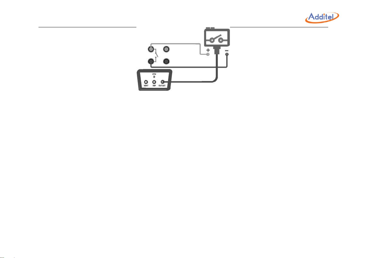
Connect the switch as shown in Figure 3-16 (it is a mechanical switch in the figure. If the
tested switch type is NPN or PNP electronic switch, please connect the electric circuit as shown in
Figure 3-8 or 3-9).
3. Capture of the action value
To capture more accurate action values, you can enter "control settings” and set the slew
rate to a lower value which will reduce the lag time between the calibrator and the switch.
Separately use the upper and lower range limits of switch as the target value for pressure
control until the switch acts. Then, capture and display the action value.
Page 67
55
Figure 3- 16 Calibration of a pressure switch
4. Record the captured action value, or use snapshot storage (it can store a pair of action values at
the same time).
3.6.5 I/P converter
1. Prepare
Switch the electrical output item of main operation interface to: Current output.
Open the pressure output area of main interface and switch to the measurement state:
High-pressure or low-pressure range (depends on the range of the I/P converter).
The output pressure of I/P converter can be measured by using an external pressure
module.
2. Connection
Connect as shown in Figure 3-17.
Never apply pressure out of the present range of the calibrator.
Page 68
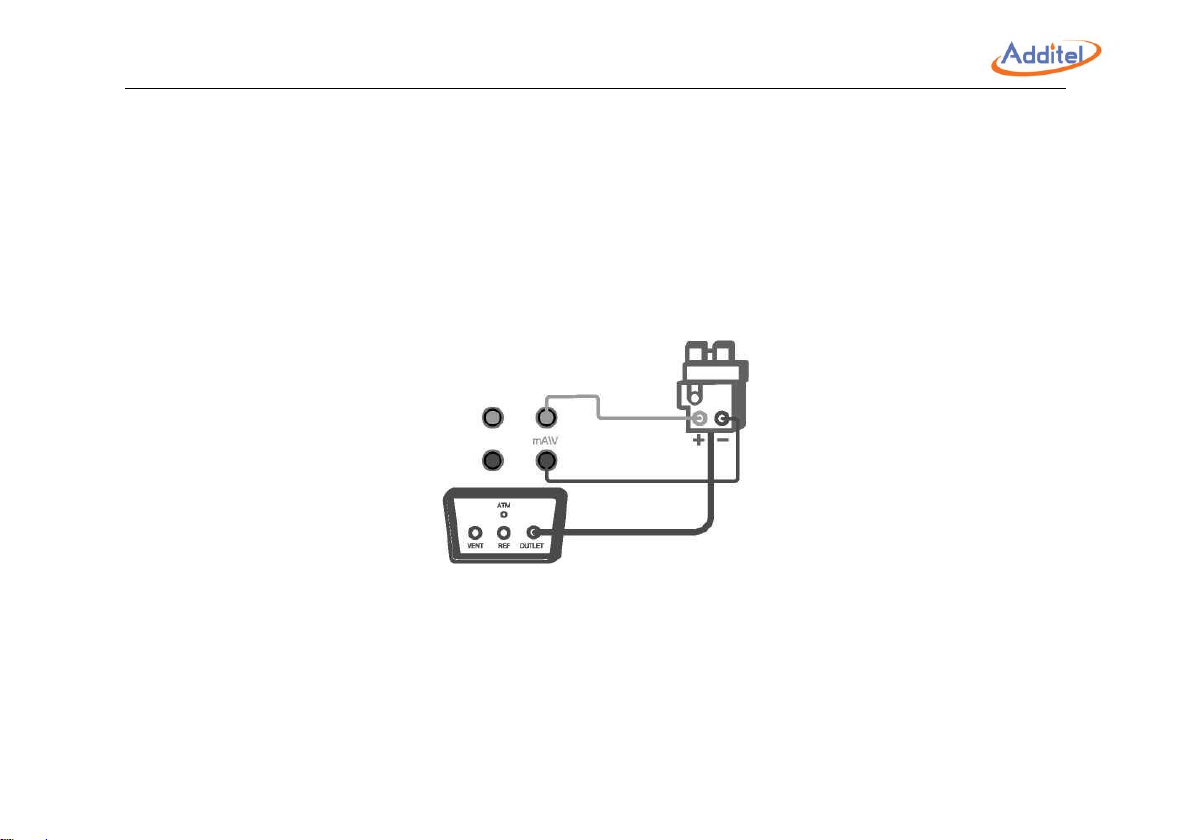
56
Never use the calibrator for pressurization.
If the loop power supply of calibrator is used (the maximum load is 50 mA), please check the
load capacity.
3. The I/P converter shall use the manual or automatic step function of electrical output (see Section
3.4 Automatic and manual step of electrical output), to successively output current of each calibration
point.
4. When each measured pressure value becomes stable, record the output value of I/P converter at
each point, or use the snapshot feature.
Figure 3- 17 Calibration of an I/P converter
Page 69
57
4. System setup
Under the main interface, press the key to enter the system setup interface. Or click on the
screen, then a main menu will pop up. Select " Set up" on the main menu to enter the system setup
interface. System setup includes control setting, communication, power management, calibration,
service, personalization, cloud service, data management and product information.
4.1 Control settings
1. Pressure type
The ADT761A-500 and ADT761A-1K support switching between gauge pressure and
absolute pressure.
2. Slew rate limit
If disabled, the calibrator will approach the target value at the maximum control speed.
If enabled, you need to set an upper slew limit. During pressure control of the calibrator, the
maximum control speed shall not exceed this limit.
3. Stability
Input the pressure stability: One of pressure stability conditions. Compare the difference
between the output pressure and set pressure with this value. Its range is ±(0.003~1)%FS.
4. Stabilization time
Input the pressure stabilization time: One of pressure stability conditions. Pressure control is
considered stable when the difference between the output pressure and set pressure meets
requirements and lasts for this duration. Its range is 1~60sec.
The pressure can be judged stable when the following two conditions are met during control:
Page 70

58
1) (Out put pressure-set pressure)<=High-pressure/low-pressure range X pressure stability
2) Meet the condition 1) continuously and reach the pressure stabilization time.
5. Automatic zeroing
Can be enabled or disabled.
If enabled, the calibrator will automatically perform pressure zeroing when vented to the
atmosphere.
6. Vent pressure
Allowable setting range of the vent pressure: Depend on the device model.
Press the “Vent” key to vent. If the pressure is lower than this value, the calibrator will open
the vent valve for direct connection to the atmosphere. If the pressure is higher than this value, the
calibrator will control the pressure below this value and then open the vent valve for direct connection
to the atmosphere.
7. Head correction
The correction type can be selected from: auto or fixed.
The unit can be selected from: metric (SI) or imperial (BS)
The density can be selected from: air, nitrogen or user-defined value;
The height can be input within the range of (-1000~1000) cm.
The acceleration can be input within the range of (9~10) m/s2.
The temperature can be input within the range of (0~100) °C.
8. Set point limit
Input a range smaller than the calibrator range as the upper and lower limits of pressure
control, to ensure that the pressure output to the calibrated device does not exceed its range, thereby
Page 71
59
protecting the calibrated device.
If disabled, this function is invalid. The setting will be stored by the calibrator and still effective
after reboot.
If enabled, the target value of pressure control of the calibrator is restricted by this condition.
When exceeding this condition, the calibrator will give a prompt that the set point limit is enabled and
the designated pressure cannot be out puted.
4.2 Communication
The calibrator supports three communication modes: Ethernet, Wi-Fi and Bluetooth (BLE).
4.2.1 Ethernet
The calibrator is connected via network cables to computers for communication.
Item
Effective value
Description
Address
acquisition
DHCP/static
Select the acquisition mode of device address.
Table 4-1 Network connecting
When the DHCP mode is selected, the content of the table below will be allocated by the
system automatically and are read-only items.
Page 72
60
When the static mode is selected, the following table needs to be completed manually.
Item
Effective value
Description
I/P address
0.0.0.0~255.255.255.255
Set the IP address of calibrator host.
Subnet mask
0.0.0.0~255.255.255.255
Set the subnet mask of calibrator host.
Gateway
0.0.0.0~255.255.255.255
Set the source gateway of calibrator host.
Table 4-2 static mode selection
The port number and physical address are factory settings and cannot be modified.
Click the button at the lower right corner of screen confirms and saves the settings.
4.2.2 Wireless communication
The calibrator is connected via a wireless network.
Item
Effective value
Description
I/P address
0.0.0.0~255.255.255.255
Set the IP address of calibrator host.
Subnet mask
0.0.0.0~255.255.255.255
Set the subnet mask of calibrator host.
Gateway
0.0.0.0~255.255.255.255
Set the source gateway of calibrator host.
Table 4-3 Wireless network selection
The port number and physical address are factory settings and cannot be modified.
When the static mode is selected in advanced options, the following table needs to be
Page 73
61
completed manually.
Item
Effective value
Description
I/P address
0.0.0.0~255.255.255.255
Set the IP address of calibrator host.
Subnet mask
0.0.0.0~255.255.255.255
Set the subnet mask of calibrator host.
Gateway
0.0.0.0~255.255.255.255
Set the source gateway of calibrator host.
Table 4-4Setup of wireless communication
Click the button at the lower right corner of screen to confirm and save the settings.
The setting of wireless communication will take effect immediately, with no need for
confirmation. Click 5 at the upper right corner of screen, to return to the previous menu.
4.2.3 Bluetooth
The calibrator is connected through Bluetooth to mobile APPs for communication.
Item
Effective value
Description
Bluetooth state
Enable/disable
Enable or disable the Bluetooth function.
Bluetooth
name
Support Chinese characters,
letters, numbers or symbols.
Set the Bluetooth name of calibrator.
Physical
Read-only
Page 74
62
address
Table 4-5 Bluetooth setup
4.3 Power management
4.3.1 Display brightness
The LCD brightness of calibrator can be modified by adjusting the brightness progress bar.
4.3.2 Battery information
Display the present connection state and information of the battery.
4.3.3 Energy settings
The energy settings can prolong the service life of the battery by setting the auto-backlight time,
auto-sleep time and auto-shutdown time.
1. Backlight time
In case there is no key and serial port command operations within a set time, the backlight
brightness will be automatically set to the lowest value.
There are 6 types of setting: never, 30 sec, 1 min, 5 min, 15 min, and 30 min.
When the backlight is turned off, the first key-press will resume the backlight brightness, only
after which subsequent key-pressing can take effect normally.
During pressure control, auto step or task execution, this function does not take effect.
2. Auto sleep
In case there is no key and serial port command operations within a set time, it will
Page 75

63
automatically sleep.
There are 4 types of auto-sleep setting: never, 1 min, 5 min and 30 min.
If connected to a power adapter, the calibrator does not support auto sleep.
During pressure control, auto step or task execution, this function does not take effect.
When the backlight off time is set to "never", the auto-sleep setting is invalid.
3. Auto power off
In case there is no key and serial port command operations within a set time, it will
automatically shut down.
There are 5 types of auto power off settings: never, 5 min, 15 min, 30 min, 1 hour and 2
hours.
If connected to a power adapter, the calibrator does not support auto power off.
During pressure control, auto step or task execution, this function does not take effect.
When the backlight off time or auto sleep time is set to "never", the setting of auto power off
is invalid.
4.4 System calibration
The electrical measurement, electrical output and internal pressure modules of this calibrator
all need periodic calibration.
This calibrator can also provide calibration for external pressure.
Before calibration, please carefully read the user manual, and perform operation after you
have understood it.
Improper calibration will affect the accuracy of calibrator, and in severe cases, may affect
Page 76

64
normal working of the calibrator.
Provided is a factory reset function to restore calibration data to factory settings. When
performed the calibration date is restored to "----/--/--".
You need to use a standard device with higher accuracy for calibration.
On the setup interface, enter system calibration and select an item to be calibrated.
To avoid mis-operation, this operation needs a password for confirmation. The password is
"123456".
After the calibration of the last point is completed, confirm and save it. The new calibration
data will take effect and be used. The former calibration data will be deleted permanently.
The calibrator provides a calibration notification warning. The default calibration period is 365
days. After a specific module of calibrator exceeds the calibration period, it will give a prompt
when the calibrator is powered on or the module is online. You can enable/disable the warning
function or modify the calibration period on the setup interface of calibration expiry warning.
4.4.1 Calibration of electrical measurement
1. Set the calibration points
Several calibration points are provided by default according to the electrical measurement
range of the device.
The calibration points can be modified. Please do not exceed the range given by the system.
Except under special circumstances, modification is not suggested.
2. Perform calibration
Page 77
65
Press the start icon at the right bottom of screen or press the key to start calibration.
According to the calibrator's prompt, make the standard current/voltage source successively
output standard current/voltage of each calibration point to the calibrator. Until the measured value
becomes stable, press the icon on the right side of screen or press the key to record and
continue.
Before final completion of calibration, you can return to the previous operation by using the
icon or key anytime, until exiting the entire calibration function. This calibration
adjustments will not take effect.
If the measured value deviates greatly from the calibration point, it will give a prompt.
After calibration is completed successfully, it will take effect immediately.
3. Restore the factory calibration data.
Click on the right side of screen, to restore the factory data.
4.4.2 Auto tune
Auto tune can optimize controller parameters which have reduced after long-term use, so as to
improve the pressure control stability and efficiency.
Caution: Please seal the pressure outlet. Auto tune is necessary only when the pressure calibrator is
not performing to specification. Incorrect or unnecessary auto tune may influence the control
performance. Please carefully use this function.
Page 78

66
4.4.3 Calibration of the supply pressure module
Calibrate the air intake and vent sensors inside the calibrator through an internal pressure control
module, to rectify pressure drift caused by long-term operation of internal sensors. During execution,
the pressure outlet shall be sealed.
4.4.4 Calibration of the barometric pressure module
The calibrator provides single-point or two-point calibration for the internal barometric pressure
module.
Single-point calibration
Input the external atmospheric pressure as standard pressure value. Confirm and click the "Save"
button to complete calibration.
Two-point calibration
1) Provide a pressure connection
Connect the calibrator as shown in Figure 4-1.
2) Set the calibration points
The default calibration point is a calibration point used in the last calibration.
The calibration point can be modified. Please ensure that the input set value of
calibration point is within the range of internal barometric pressure module, and the value of
point 1 is less than that of point 2.
Page 79
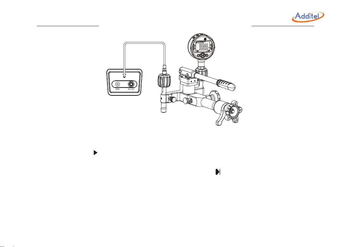
67
Figure 4- 1 Calibrate an barometric pressure module
3) Perform calibration
Click to perform calibration.
According to the calibrator's prompt, make the standard instrument output pressure to
the calibrator. Until the pressure becomes stable, click to perform calibration of the next
point.
If the measured value deviates greatly from the calibration point, it will give a prompt.
After calibration is completed successfully, new calibration data will take effect
immediately, and the calibration date is recorded in the system.
Page 80

68
4.4.5 Pressure calibration
1. Connection
Calibration of the internal pressure module can select internal pressurization or external
pressurization mode.
When the internal pressurization mode is selected, please connect the pressure outlet of
calibrator to the standard pressure instrument.
When the external pressurization mode is selected, please connect the calibrator to the
pressure generation of the standard.
During calibration of the external pressure module, if the calibrated pressure module is
covered by the pressure supply range of internal pressure source, you can select internal or external
pressurization. If it is not covered, you can only select external pressurization.
2. Set the calibration points
Calibrate the internal pressure module of calibrator through 3 points.
Default calibration points are the lower limit, zero point and upper limit of the internal pressure
module.
Calibrate the external pressure module of calibrator through 2 points.
Default calibration points are the lower limit and upper limit of the external pressure module.
The calibration points can be modified. Please ensure that the input set values of calibration
points are within the range of internal pressure module, and point 1<point 2<point 3. Except under
special circumstances, modification is not suggested.
Page 81

69
3. Perform calibration
Click to perform calibration.
Internal pressurization: According to the calibrator's prompt, make the calibrator output
pressure to the standard instrument. Until the pressure becomes stable, click the measured value
corresponding to this calibration point, and input the pressure reading of standard instrument. After
confirmation, click to perform calibration of the next point.
External pressurization:
According to the calibrator's prompt, make the standard instrument output pressure to the calibrator.
Until the pressure becomes stable, click to perform calibration of the next point.
Caution: Please adjust the pressure output of standard instrument to be the same as the set value of
calibration point of the calibrator.
If the measured value deviates greatly from the calibration point, it will give a prompt.
After calibration is completed successfully, new calibration data will take effect immediately,
and the calibration date becomes the present system date.
4. Restore factory calibration data
Click on the right side of screen, to restore the factory data.
4.5 Services
4.5.1 System upgrade
The calibrator provides a function of firmware upgrade. The upgrade operation includes two types:
Local upgrade via a USB flash drive or remote upgrade
Page 82

70
Local upgrade via a USB flash drive
1) Copy the upgrade file under the root directory of USB flash drive (ensure that the format
of USB flash drive is FAT16 or FAT32).
2) After power-on, insert the USB flash drive into the USB-A port on the left side of
calibrator.
3) Select "Upgrade via USB" on the upgrade interface.
4) Click . The calibrator will analyze the upgrade file and display information that it is
going to upgrade. After confirmation, the system will start automatic upgrade.
5) Wait for several minutes until the upgrade program is finished. The system will
automatically display the upgrade result. After confirmation, the system will reboot automatically.
Remote upgrade
1) You can click manually to check the latest firmware version or start automatic upgrade.
2) Remote upgrade shall ensure that the calibrator can be connected to the external
network through LAN Ethernet or Wi-Fi.
4.5.2 Maintenance
Maintenance needs inputting a password. The factory default password is: 123456
Maintenance is used to record the maintenance records, calibration records, and system
board upgrade information of the device; and can also execute operation to clear system records.
Maintenance records: Users can add the maintenance personnel, date, content and brief
information, which is displayed in the form of list.
Calibration records: Record related information of each calibration, including the calibration
Page 83
71
item, calibration time, and detailed calibration data. Users can search and browse it by date and time.
4.5.3 Factory reset
Factory reset requires a password. The factory default password is: 123456. After reset, data
clearing is irreversible. Please carefully use this function.
Restores the user settings to defaults, and clear snapshot and task files.
Inputs the password to enter the factory reset interface. A prompt box will pop up to ask
whether you confirm it. Click "OK" or press the key to immediately execute the reset operation.
Click "Cancel" or press the key to cancel operation.
Factory reset will not restore system calibration data. If you need to restore the system
calibration data, please refer to Section 3.7 "System calibration".
After factory reset and reboot, users need to set the date/time. See Section 4.6.1.
4.6 Personalization
Personalization includes date and time, language, and sound settings.
Page 84
72
4.6.1 Date and time
Item
Effective value
Description
Time
00:00~23:59
Set the time.
Date
2000-1-1~2099-12-31
Set the date.
Date
format
Year-month-day/month-day-year/day-month-year
Set the date format.
Separator
-,/,.
Set the date separator.
Table 4-6 Date and time
4.6.2 Language
The device provides multi-language interfaces. You can select a suitable language interface
through this menu.
When selected, the language interface will take effect after rebooting the device.
4.6.3 Sound
Item
Effective value
Description
Volume
Volume setting in the form of a
progress bar
Set the device volume.
Touch sound
On/off
Enables/disables the sound for the touch screen
display.
Prompt sound
On/off
Enables/disables the prompt sound
Page 85
73
Over-range
warning sound
On/off
Enables/disables the sound for over-range warning
Snapshot
sound
On/off
Enables/disables the sound for when a snapshot is
taken
Stable sound
On/off
Enables/disables the sound indicating the stability
criteria has been meet
Table 4- 7 Sound setup
Page 86
74
4.7 Cloud service
Provided through Ethernet or Wi-Fi methods for connection to the ACIoud service. Through
Additel Link (providing several client modes such as mobile APP and PC), users can monitor the
real-time operation status and data of the device anytime anywhere.
After the cloud service is enabled, the top status bar of main interface will display a cloud
service state icon or , respectively indicating that connection to the cloud service
succeeded or failed.
Item
Effective value
Description
Enable
On/off
Enable or disable the cloud service function.
Table 4-8 Setup of cloud service
4.8 Data management
Perform management by function modules. Data management of each function is under the
corresponding item for convenience.
Function modules that can save data files include: Snapshot, pressure leakage test, etc.
Users can export data in the format of CSV through a USB flash drive or PC software.
Users can delete data in batches.
4.9 Product information
The product information includes calibrator host information, control board information, electrical
Page 87

75
measurement board information, electrical source board information, wireless module information,
Profibus module information and HART communicator information.
Page 88

76
4.9.1 Host information
Includes the model, serial number, host version, system firmware version, system hardware
version, power-on times, operation time, etc. Generally, the firmware version refers to host version.
When contacting customer service, please provide this information.
4.9.2 Control board information
Includes the software version and hardware version of control panel, and the parameters of
internal pressure module.
The parameters of internal pressure module include: Model, range, number and calibration
date.
4.9.3 Electrical measurement board information
Includes the software version and hardware version of electrical measurement board, as well
as current and voltage measurement parameters.
The current and voltage measurement parameters include: Range, accuracy and calibration
date.
4.9.4 Electrical source board information
Include the software version and hardware version of electrical source board, as well as the
current and voltage parameters of electrical output.
The current and voltage parameters of electrical source include: Output range, accuracy and
Page 89

77
calibration date.
4.9.5 Wireless module information
Include the Wi-Fi version, Bluetooth version, etc.
4.9.6 PROFIBUS module information
Include the firmware version and hardware version of PROFIBUS module. The PROFIBUS
module is used to realize related functions of communication with transmitters.
4.9.7 HART handheld communicator information
Include the DD library version, etc.
5. Documentation
5.1 Quick test
Click the main menu icon on the main interface, and then select the icon to enter the
quick test function, and the calibrator displays the test type list. The quick test function doesn’t require
test information to be entered in advance.
5.1.1 Pressure gauge
Select the “pressure gauge” icon in the test type list to start the quick test of the pressure
Page 90
78
gauge.
1. Connection
Connect as shown in Figure 3-16 when testing an analog gauge;.
Connect as shown in Figure 5-1 when testing a digital pressure gauge.
2. Start the test
Click the zeroing button to reset the pressure control module.
Click the start button to select the automatic execution to enter the execution parameter
setting interface. Fill in the set point list, the number of cycles, the stroke mode, the number of
readings, the reading interval, and the dwell time, and then click the OK button to start the test.
The test data will be manually entered at each point of the test.
Click the next icon to skip the current test point and enter the next test point for pressure
control.
Selecting manual execution requires the test point to be entered as the test progresses.
To stop this test, click the back button .
3. Save the result
Click the save button to save the test result.
The following items will need to be entered: Name and serial number. Then click the check
mark in the lower right corner to complete the save the results.
To exit without saving press the back button .
To redo the test click the reset button .
Page 91
79
5.1.2 Pressure transmitter
Select the “pressure transmitter” icon in the test type list to start the quick.
1. Connection
Refer to Section 3.6.2 for connection.
2. Start the test
Click the zeroing button to reset the pressure control module.
Click the start button to select the automatic execution to enter the execution parameter
setting interface. Fill in the set point list, the number of cycles, the stroke mode, the number of
readings, the reading interval, and the dwell time, and then click the OK button to start the test.
When selecting the manual execution, after the set point is stable, it is required to click the
next point button to collect data and then input the new set point.
To stop this test, click the back button .
3. Save the result
Click the save button to save the test result.
The following items need to be entered: Name and serial number, click OK button to
save the test results.
To exit without saving press the back button .
To redo the test click the reset button .
Page 92
80
5.1.3 Pressure switch
Select the “pressure switch” icon in the test type list to start the quick test.
1. Connection
Connect the switch as shown in Figure 3-20.
2. Start the test
Click the zeroing button to reset the pressure control module;
Click the start button to select to enter the execution interface;
Select the graph display button and the table display button to switch between the
graph display or table display.
Pressure switch action: When the internal pressure module is used as the standard, it will be
automatically run the test. When the external pressure module is used as the standard manual
pressure generation is required and the switch data will be recorded.
To stop this test, click the back button .
3. Save the result
Click the save button to save the test result.
The following items need to be entered: Name and serial number, click OK button to
save the test results.
To exit without saving press the back button .
Page 93

81
To redo the test click the reset button .
5.1.4 Pressure sensor
Select the “pressure sensor” icon in the test type list to start the quick test.
1. Connection
Connect the sensor as shown in Figure 5-2.
2. Start the test
Same as Section 5.1.2 Pressure transmitter.
3. Save the result
Same as Section 5.1.2 Pressure transmitter.
5.1.5 I/P converter
Select the “I/P converter” icon in the test type list to start the quick test.
1. Connection
Connect as shown in Figure 3-21.
2. Start the test
Same as Section 5.1.2 Pressure transmitter.
3. Save the result
Same as Section 5.1.2 Pressure transmitter.
Page 94
82
5.1.6 Signal isolator
Select the “signal isolator” icon in the test type list to start the quick test.
1. Connection
Connect as shown in Figure 5-3.
2. Start the test
Same as Section 5.1.2 Pressure transmitter.
3. Save the result
Same as Section 5.1.2 Pressure transmitter.
5.2 Task
The calibrator provides task functions which automate preset calibration routines, and collect,
record, and save test data.
Enter the task interface: Click , and select the task in the menu .
Task list interface: Click on the right side of the screen to create a new task, click to
delete tasks, and click to create a new folder.
Test parameter interface: Click on the right side of the screen to delete the task, click
to edit the task, click to copy the task, and click to start the task.
5.2.1 Analog pressure gauge
1. Connection
Connect the calibrator and the analog pressure gauge as shown in Figure 3-14.
Page 95
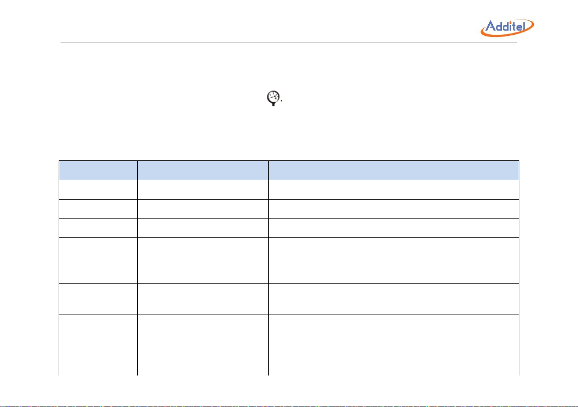
83
It is recommended to connect the reference port (REF) when calibrating a differential
pressure device.
2. New task
Select the “analog pressure gauge” icon in the test type list, and input the information of the
pressure gauge.
Item
Effective value
Description
Name
Letter, numeral, symbol
Name of the pressure gauge
Serial number
Letter, numeral, symbol
Serial number of the pressure gauge
Model
Letter, numeral, symbol
Model of the pressure gauge
Pressure type
Gauge pressure, absolute
pressure, differential
pressure
Pressure type of the pressure gauge
Range
Depends on the pressure
gauge
Range and unit of the pressure gauge
Accuracy
0.06%, 0.1%, 0.16%,
0.25%, 0.4%, 0.6%, 1%,
1.6%, 2.5%, 4%, and
custom
Precision of the pressure gauge. The numeric input in
the custom option is the accuracy of the pressure
gauge. For example: For 1.5% accuracy would be
input as 1.5 through the numeric keyboard, which has
Page 96
84
a range of (0.001 ~ 100)%
Resolution
Resolution: 0.000001
The resolution of the pressure gauge
Owner
Letter, numeral, symbol
Owner of the pressure gauge
Location
Letter, numeral, symbol
Location position of the pressure gauge
Note
Letter, numeral, symbol
Notes of the pressure gauge
Table 5- 1 Task mode analog pressure gauge information
Page 97
85
3. Task setting features
Select the task in the task list to enter the instrument parameter interface, click the start icon to enter
the execution information interface, and input the calibration information of the pressure gauge .
Item
Effective value
Description
Set points
The effective value of the
set point pressure
depends on the pressure
range of the gauge; up to
17 calibration points can
be set
Set the calibration points for the task, and the
calibrator will automatically set the default calibration
point based on the range of the calibrated
instrument and the number of the calibration points.
Any point can be manually selected to be changed
to a different point. The set point needs to be within
the range of the pressure gauge. Change the
number of the calibration points through the arrow
key on the right side of the screen or by clicking the
number of the calibration points.
Cycle number
1, 2, 3
Select the number of cycles
Stroke
Round trip and one way
Select the calibration task stroke mode
The number of
readings
Integer of 1 ~ 6
Input the number of readings to be taken when the
calibrator reaches the set point
Reading interval
Integer of (1 ~ 600)
seconds
Interval time between two readings
Page 98
86
Dwell time
Integer of (1 ~ 600)
seconds
The waiting time before readings are taken and the
calibrator advances to the next set point.
Input format
Value, the number of
scales
1. Value: Digital display of pressure value
2. The number of scales: The pressure value is
displayed by counting the number of scales to
facilitate the reading and comparison with the value
indicated by the analog pressure reading. The
calibrated reading = standard value + deviation
number of scales X minimum scale division
Tapping
Enable, disable
When enabled the value of the analog pressure
gauge needs to be input twice for each calibration
point, and then the calibrator will shift to the next
calibration point to continue the task.
Table 5- 2 Task setting of analog pressure gauge
4. Task start
Click to start the task process:
Page 99

87
If connecting an external pressure module the correct standard should be selected
Click on the right to zero the pressure of the pressure module.
Click the task start button at the bottom right, and select the execution mode as automatic
execution or manual execution.
1) Automatic execution: The default measurement value is the same as the set point value.
The measured value can be manually changed.
2) Manual execution: Every time a set point is reached, the value will need to be entered
before advancing to the next set point.
The display icon to the right will change the display from graphical to numeric.
Standard process of calibration
1) When the calibration point is reached and stable, enter the measurement value for the
analog pressure gauge.
2) Click the Enter key on the keyboard or in the lower right corner of the screen to
advance to the next calibration point. At this time, the calibrator will start to control the pressure. The
automatic execution mode can be performed without manually advancing if the measurement value is
the same as the set point value. ★ When enabling the tapping function, pay attention to the status
before/after tapping as prompted by the function screen, and input the indicated value of the gauge
before/after tapping.
4) Repeat Step 2&3 until the entire pressure calibration process is completed;
After the entire calibration process is completed, it will automatically enter the report
interface.
Page 100
88
5. Task end
The ADT761A provides calibration task data review, sorting and save functions.
After the task is over, the user can choose to see the result of the task through the data view
icon or the task data.
The user can also click to abandon the task data and execute the task again.
Task data can be stored by clicking in the save interface and the following information can
be entered:
Item
Effective value
Description
Operator
Letter, numeral, symbol
Calibration task operator information
Execution time
2000/01/01-2099/12/31
Calibrator task execution date
Ambient
temperature
Numeral
Ambient temperature during task
Temperature unit
К, °C, °F
Unit of ambient temperature during task
Ambient humidity
Numeral
Ambient humidity during task
Save as
As found, as left and both
Save pre-adjustment data or post-adjustment data,
or both
Table 5- 3 Task save
After saving, return to the task interface.
 Loading...