

Page 1
226/227
Multifunction Process Calibrator
Page 2

ADT226/227 Multifunction Process Calibrator
-------User Manual
[Version:2111V01]
Additel Corporation
Page 3

STATEMENT
This user manual provides operating and safety instructions for the ADT226/227 Multifunction
process calibrator. To ensure correct operation and safety, please follow the instructions in this
manual. Additel Corporation reserves the right to change the contents and other information
contained in this manual without notice.
Page 4

Page 5

I
CONTENT
1. Introduction ................................................................................................................................................................... 2
1.1 General Introduction .................................................................................................................................................. 2
1.2 Models and function ................................................................................................................................................... 3
1.3 Technical Specifications ............................................................................................................................................. 6
1.3.1 General specifications ......................................................................................................................................... 6
1.3.2 Electrical Measurement Specifications ................................................................................................................ 7
1.3.3 Electrical Output Specifications ......................................................................................................................... 10
1.3.4 RTD Measurement and Source Specifications .................................................................................................. 11
1.3.5 Thermocouple Measurement and Source specifications ................................................................................... 13
1.4 Basic Structure ........................................................................................................................................................ 17
1.5 Power supply description ......................................................................................................................................... 18
2. Display and functions ................................................................................................................................................. 20
2.1 Main interface .......................................................................................................................................................... 20
2.2 Control center .......................................................................................................................................................... 21
3. Calibrator ..................................................................................................................................................................... 22
3.1 Electrical Measurement ........................................................................................................................................... 24
3.1.1 DC voltage measurement .................................................................................................................................. 24
3.1.2 Current measurement ........................................................................................................................................ 25
3.1.3 Switch measurement ......................................................................................................................................... 26
Page 6

II
3.1.4 Pulse measurement ........................................................................................................................................... 26
3.1.5 Frequency measurement ................................................................................................................................... 26
3.1.6 AC voltage measurement .................................................................................................................................. 26
3.1.7 Scaling ............................................................................................................................................................... 27
3.1.8 Filter .................................................................................................................................................................. 27
3.1.9 Zeroing .............................................................................................................................................................. 28
3.1.10 Statistics .......................................................................................................................................................... 28
3.2 Pressure measurement ............................................................................................................................................ 28
3.2.1 Pressure measurement settings ........................................................................................................................ 29
3.2.2 Filter .................................................................................................................................................................. 30
3.2.3 Module information ............................................................................................................................................ 30
3.2.4 Zeroing .............................................................................................................................................................. 30
3.2.5 Statistics ............................................................................................................................................................ 30
3.3 Temperature measurement ...................................................................................................................................... 30
3.3.1 Thermocouple measurement ............................................................................................................................. 30
3.3.2 Thermocouple settings ...................................................................................................................................... 31
3.3.3 RTD measurement ............................................................................................................................................ 32
3.3.4 RTD settings ...................................................................................................................................................... 32
3.3.5 Zeroing .............................................................................................................................................................. 33
3.3.6 Statistics ............................................................................................................................................................ 33
3.4 HART calibration ...................................................................................................................................................... 33
3.4.1 Search and connection ...................................................................................................................................... 34
Page 7

III
3.4.2 HART Setting ..................................................................................................................................................... 34
3.4.3 Process variables .............................................................................................................................................. 36
3.4.4 Diagnosis/ Service ............................................................................................................................................. 36
3.5 Output ...................................................................................................................................................................... 39
3.5.1 Voltage output.................................................................................................................................................... 39
3.5.2 Current output.................................................................................................................................................... 40
3.5.3 Frequency output ............................................................................................................................................... 40
3.5.4 Pulse output ...................................................................................................................................................... 41
3.5.5 Simulate Thermocouple (TC) output .................................................................................................................. 41
3.5.6 Simulate RTD output ......................................................................................................................................... 42
3.5.7 Set point output ................................................................................................................................................. 44
3.5.8 Ramp output ...................................................................................................................................................... 44
3.5.9 Automatic step output ........................................................................................................................................ 45
3.5.10 Manual step output .......................................................................................................................................... 46
3.5.11 Fine adjustment output .................................................................................................................................... 47
4. System settings ........................................................................................................................................................... 48
4.1 Bluetooth communication ......................................................................................................................................... 48
4.2 Power management ................................................................................................................................................. 48
4.2.1 Brightness ......................................................................................................................................................... 48
4.2.2 Battery information ............................................................................................................................................ 48
4.2.3 Auto backlight off ............................................................................................................................................... 48
4.2.4 Auto sleep after backlight off.............................................................................................................................. 49
Page 8

IV
4.2.5 Auto power off after sleep .................................................................................................................................. 49
4.3 Services ................................................................................................................................................................... 49
4.3.1 System calibration ............................................................................................... Error! Bookmark not defined.
4.3.2 Maintenance ...................................................................................................................................................... 50
4.3.3 4.3.3 Restore to factory data ............................................................................................................................. 50
4.4 Personalization ........................................................................................................................................................ 50
4.4.1 Sound ................................................................................................................................................................ 50
4.4.2 Language .......................................................................................................................................................... 51
4.4.3 Date & Time ....................................................................................................................................................... 51
4.5 Product information .................................................................................................................................................. 52
5. Data management ....................................................................................................................................................... 52
6. Task .............................................................................................................................................................................. 53
6.1 Calibration pressure devices .................................................................................................................................... 53
6.1.1 Dial pressure gauge and digital pressure gauge ............................................................................................... 53
6.1.2 Pressure transmitter .......................................................................................................................................... 57
6.1.3 Pressure switch ................................................................ ................................................................................. 59
6.1.4 I/P Converter ..................................................................................................................................................... 60
6.2 Calibrate temperature devices ................................................................................................................................. 63
6.2.1 Temperature indicator ........................................................................................................................................ 63
6.2.2 Temperature transmitter..................................................................................................................................... 64
6.2.3 Temperature transmitter with sensor ................................................................................................................. 67
6.2.4 Temperature switch ........................................................................................................................................... 69
Page 9

V
6.2.5 Temperature switch with sensor ........................................................................................................................ 72
6.3 Calibrate flow devices .............................................................................................................................................. 75
6.3.1 Delta- pressure flowmeter ................................................................................................................................. 75
6.3.2 Instantaneous flowmeter ................................................................................................................................... 76
6.3.3 Flow volume totalizers ....................................................................................................................................... 78
6.3.4 Tachometer/ vortex meters ................................................................................................................................ 79
6.4 Calibrate loop devices .............................................................................................................................................. 81
6.4.1 Loop indicators ................................................................................................................................ .................. 81
6.4.2 Loop signal source ............................................................................................................................................ 83
6.4.3 Signal isolator/ converters ................................................................................................................................. 84
6.4.4 Limit Switches.................................................................................................................................................... 86
7. Applications ................................................................................................................................................................. 87
7.1 Pressure Unit Converter .......................................................................................................................................... 87
7.2 Leak Test ................................................................................................................................................................. 88
7.3 PSV test ................................................................................................................................................................... 89
7.4 Thermal calculator ................................................................................................................................................... 90
7.5 Sensor library ........................................................................................................................................................... 90
7.6 Simulate transmitter ................................................................................................................................................. 90
7.7 Data logger .............................................................................................................................................................. 91
7.7.1 Logger Management ......................................................................................................................................... 92
7.7.2 The start of data logging .................................................................................................................................... 92
7.7.3 The operation of data logging ............................................................................................................................ 93
Page 10

VI
7.7.4 Save the data .................................................................................................................................................... 95
7.8 Differential pressure ................................................................................................................................................. 95
8. Communicator ............................................................................................................................................................. 96
8.1 HART connection and search .................................................................................................................................. 97
8.2 HART communicator operation ................................................................................................................................ 97
Page 11

1
Safety instructions
Warning:
To prevent the user from injury, please follow this user manual for use.
To prevent possible fire, electric shock or personal injury, please do as follows:
General:
◆ Please read the manual, especially the Safety Instructions before using this product
◆ Use only the correct measurement category (CAT), voltage and current rated probes, test cables for
measurement
◆ Please charge the battery when a low battery level is displayed in to prevent abnormal readings
◆ Do not expose the battery to fire or short circuit the battery
◆ The voltage applied between the terminals or between any terminal and the grounding cannot exceed the rated
value
◆ Before using the product, please check the product for any damage
◆ If the product is damaged or malfunctions, do not use it, and contact Additel
◆ Never use the non-Ex version in an explosive, steam, or dust environment
◆ Do not touch any metal parts of the probes or test cables during use;
◆ Please remove unnecessary probes, cables, or other accessories before using the product
◆ Do not use damaged or worn cables
Attention:
Page 12

2
To prevent injury, please obey the instruction manual for use
To prevent possible damage, please do as follows:
◆ Do not use the instrument in a high vibration environment
◆ Use only genuine Additel power adaptors and batteries with the product
◆ When working with external pressure modules, refer to the safety instructions of its manual.
1. Introduction
1.1 General Introduction
The ADT226/227 series calibrators are a new generation multifunction process calibrator provided by Additel. With
the documenting test task built-in, it can significantly improve the efficiency of the testing and calibrating in field and
laboratory applications. It combines a plentiful amount of functions in a single device, such as gauge measurement,
Page 13
3
signal source, loop power, pressure indicator, HART communicator and thermal calculator. Users can perform field
calibration, troubleshooting and maintenance by carrying only the ADT227, so that greatly improved the efficiency of field
engineers and technicians.
Contact us:
Additel Corporation
Tel: +1-714-998-6899
www.additel.com
1.2 Models and function
Table 1 Models and function
Models
ADT226
ADT227
ADT227-HART
Measure
Page 14
4
Voltage
mV DC
±300 mV
±300 mV
±300 mV
V DC
±30 V
±30 V
±30 V
High Voltage
V DC/AC
±300V DC/AC
±300V DC/AC
±300V DC/AC
Current (mA DC)
±30 mA
±30 mA
±30 mA
Resistance
0 - 4000 Ω
0 - 4000 Ω
0 - 4000 Ω
Frequency
0.01 - 50,000 Hz
0.01 - 50,000 Hz
0.01 - 50,000 Hz
Pulse
0 - 9,999,999
0 - 9,999,999
0 - 9,999,999
Limit Switch
• • •
Thermocouple TC
-10 - 75 mV
-10 - 75 mV
-10 - 75 mV
Pressure Module Serial Ports
2 2 2
Source / Simulate
Voltage (V DC)
0 - 15 V
0 - 15 V
0 - 15 V
Current (mA DC)
0 - 25 mA
0 - 25 mA
0 - 25 mA
Resistance
0 - 4000 Ω
0 - 4000 Ω
0 - 4000 Ω
Frequency
0.01 - 50,000 Hz
0.01 - 50,000 Hz
0.01 - 50,000 Hz
Pulse
0 - 9,999,999
0 - 9,999,999
0 - 9,999,999
Thermocouple TC
-10 - 75 mV
-10 - 75 mV
-10 - 75 mV
Recording
Scaling
• • •
Min/Max/Avg/Tare
• • •
Page 15
5
Hold
• • •
Task
• •
On-demand Logging
10,000 readings
10,000 readings
Features
Intrinsically Safe (Ex)
Color Touchscreen Display
• • •
Port Protection
50V Max
50V Max
50V Max
Loop power
24 V
24 V
24 V
Ramp/step
• • •
Simulate Transmitter
• • •
RTD
• • •
Thermocouple TC
• • •
Internal CJC
• • •
Bluetooth
• • •
HART Communication
•
Full HART Communicator
•
Documenting
• •
IP67 Compliance
• • •
Warranty
3 Years
3 Years
3 Years
ISO 17025 Accredited Calibration
• • •
Page 16
6
1.3 Technical Specifications
1.3.1 General specifications
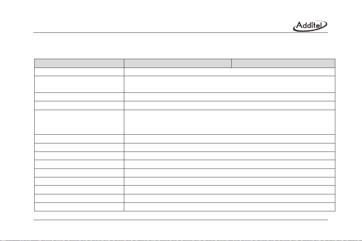
Table 2 General specifications
Specifications
ADT226
ADT227
Operating Temperature
-10°C to 50°C
Specification guaranteed
temperature
10°C to 30°C
Storage Temperature
-20°C to 70°C
Humidity
<95%, non-condensing
Power supply
6600mAh, 23.8Wh lithium battery,
charging time 4~6 hours,
battery pack can be charged independently
User interface
Icon drive menus
Ports protection voltage
50V max
Display
5.0-inch 480x800 mm TFT LCD capacitive screen
Maximum altitude
3000 meters
European Compliance
CE Mark
Electrical Connection
Ø4mm sockets and flat mini-jack thermocouple socket
Size
6.97" x 4.13" x 2.04" (177 mm x 105 mm x 52 mm)
Weight
1.6 lb (0.7 kg)
Battery
Rechargeable Li-ion battery (included)
Page 17
7
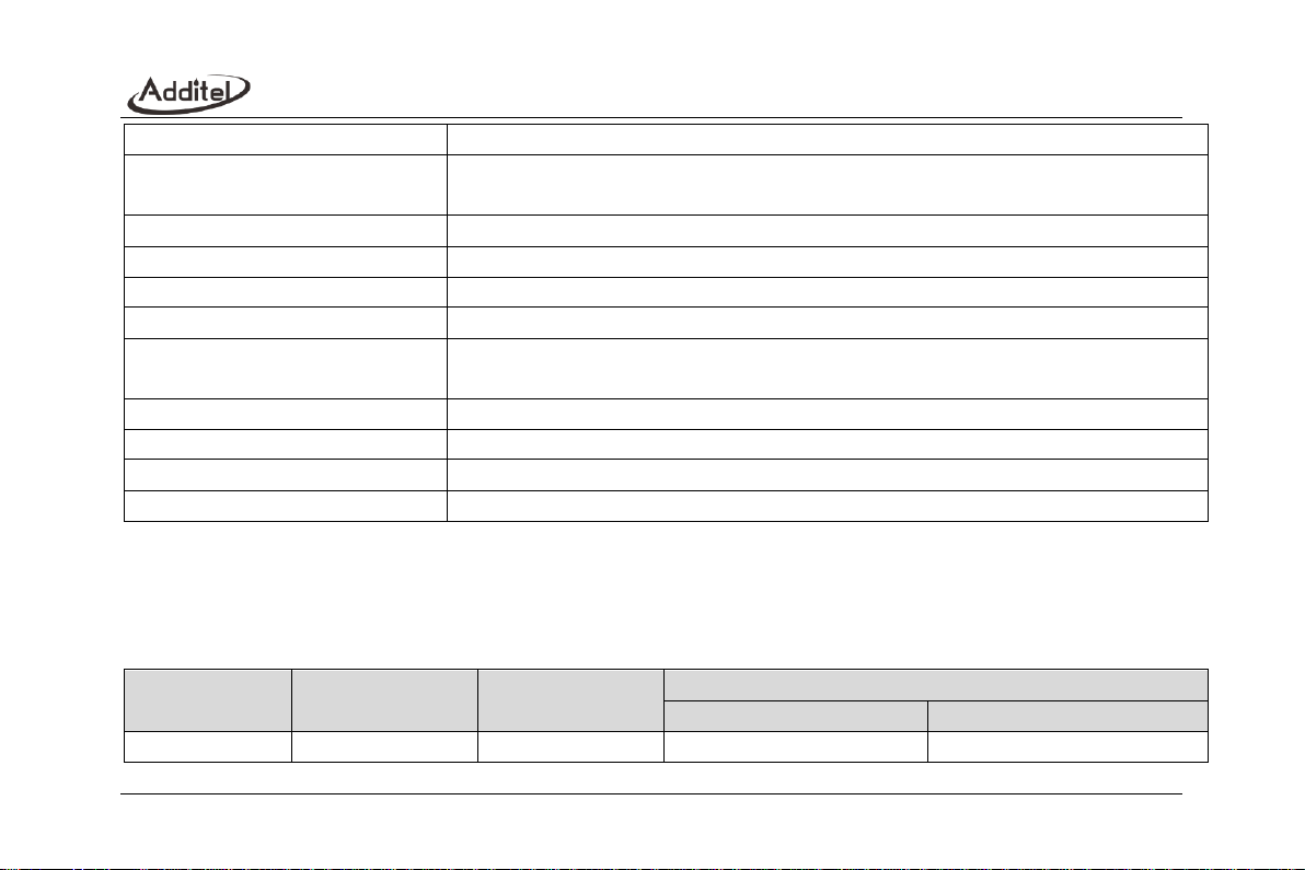
Battery Life
Typically, 16 hours
Battery Charge
110V/220V external power adapter included. Battery can be charged external to the unit.
Typically charge time is 6-8 hours.
External pressure module
Dual channel aerial plug, can connect two digital pressure modules
Warm-up time
Full specification performance is achieved after a 10-minute warm-up time.
ROHS compliant
Rohs II Directive 2011/65/EU, EN50581:2012
Display rate
3 readings per second
Barometric Accuracy (Built-in
barometer)
55Pa
IP protection level
IP67, 1 meter drop test
Communication
Isolate USB-TYPEC (slave), Bluetooth BLE
Calibration
ISO 17025 accredited calibration with data
Warranty
3 years
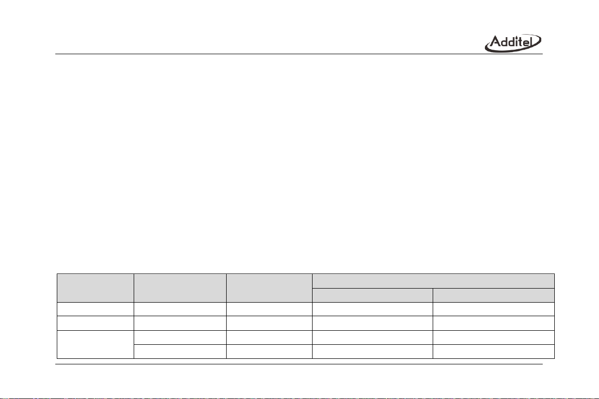
1.3.2 Electrical Measurement Specifications
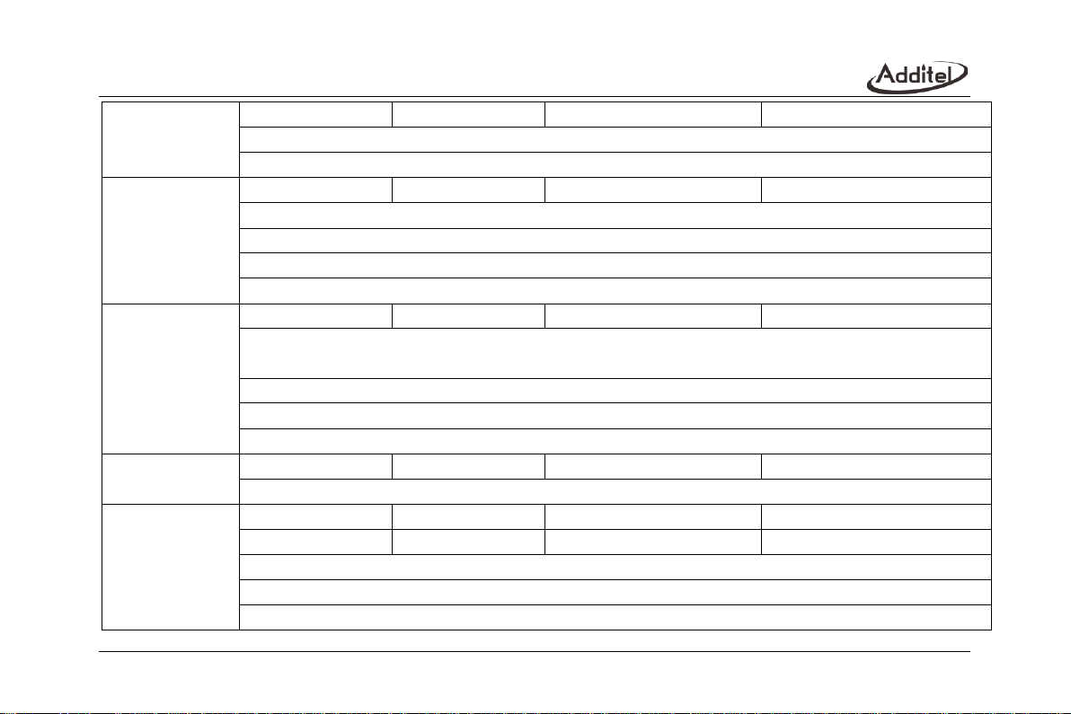
Table 3 Electrical Measurement Specifications
Specifications
Range
Resolution
Accuracy
ADT226
ADT227
Voltage DC
-300 to 300 mV
1 µV
0.015% RDG + 0.005% FS
0.005% RDG + 0.005% FS
Page 18
8
-30 to 30 V
0.1 mV
0.015% RDG + 0.005% FS
0.005% RDG + 0.005% FS
Temperature Coefficient: ±5 ppm FS/°C (-10°C to 10°C and 30°C to 50°C)
Impedance: -300 mV to 300 mV = > 100 MΩ -30 V to 30 V = >1 MΩ
DC High Voltage
-300 to 300 V
10 mV
0.05% RDG + 0.01% FS
0.05% RDG + 0.01% FS
Temperature coefficient: ±0.0025% FS/°C (-10°C to 10°C and 30°C to 50°C)
Maximum input voltage = 300 V, IEC61010 300V CATII
Common mode rejection: >100 dB (at 50 or 60 Hz)
Impedance: > 4 MΩ, DC coupling
AC High Voltage
300V (40 to 500 Hz)
10 mV
0.5% RDG + 0.05% FS
0.5% RDG + 0.05% FS
Temperature coefficient: ±(0.025% RD + 0.0025% FS
)
/°C
(-10°C to 10°C and 30°C to 50°C)
Maximum input voltage = 300 V, IEC61010 300V CATII
9% to 100% of range is suitable for the above accuracy indicators
Impedance: >4 MΩ,<100pF, AC coupling
Current DC
-30 to 30 mA
0.1 µA
0.015% RDG + 0.005% FS
0.01% RDG + 0.005% FS
Temperature Coefficient: ±5ppm FS/°C (-10°C to 10°C and 30°C to 50°C), Impedance: < 40 Ω
Resistance (4-
Wire)
0 to 400 Ω
1 mΩ
0.015% RDG + 0.005% FS
0.005% RDG + 0.005% FS
0 to 4000 Ω
10 mΩ
0.015% RDG + 0.005% FS
0.01% RDG + 0.005% FS
Temperature Coefficient: ±5 ppm FS/°C (-10°C to 10°C and 30°C to 50°C)
2-Wire + 50 mΩ, 3-wire+ 10 mΩ
Excitation current: 0.25 mA
Page 19
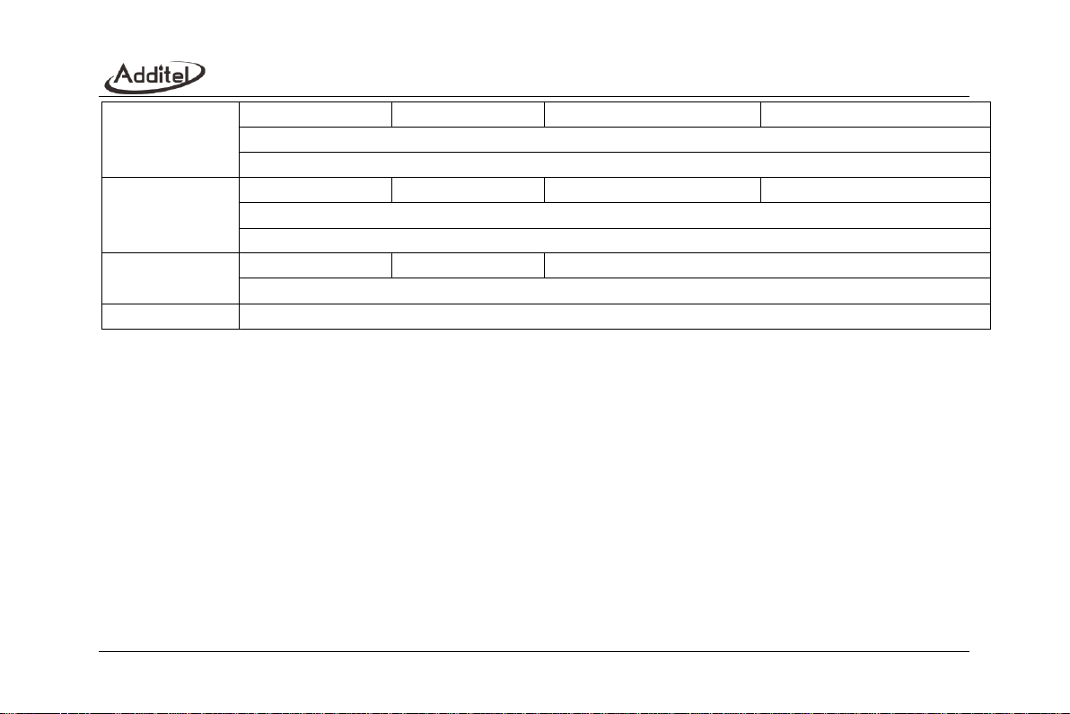
9
Voltage mV (TC)
-10 to 75 mV
0.1 µV
0.015% RDG + 0.005% FS
0.008% RDG + 0.004% FS
Temperature Coefficient: ±5ppm FS/°C (-10°C to 10°C and 30°C to 50°C)
Impedance: >100 MΩ
Frequency
0.01 to 50000 Hz
Auto range, 6-digit
0.005% RDG + 5 on last digit
0.002% RDG + 2 on last digit
Minimum threshold voltage: 2.5 V
Supported units: Hz, kHz, MHz, CPM, CPH, s, ms, µs
Pulse
0 to 9999999
1
N/A
Optional rising edge and falling edge, minimum threshold voltage: 2.5V
Switch
Supports dry or wet switches. Voltage range of 3 to 30 V. Response speed < 10ms
Note 1: When the environmental temperature is (-10~+10) ℃ and (30~50)
℃
, the temperature coefficient is:
(1) Measure of voltage, current, TC and RTD:±5ppmFS/
℃
.
(2) AC High voltage TRMS measurement,
(3) DC high voltage measurement: ±(25ppmRDG+25ppmFS)/
℃
.
Note 2: Input characteristics:
(1) Voltage scale: -300~300mV input impedance >100 MΩ;
(2) Voltage scale: -30~30V input impedance >1MΩ;
(3) Current measure: input impedance<40Ω;
(4) TC measure: input impedance >100 MΩ.
(5) AC High voltage TRMS measurement:
input impedance >4MΩ, <100pF, AC Coupling
maximum input voltage: 300V
,
IEC61010 300V CATII
applied for: 9-100% FS
Page 20
10
(6) DC high voltage measurement:
input impedance >4MΩ, DC Coupling
maximum input voltage: 300V
,
IEC61010 300V CATII
CMRR: >100 dB (50 or 60 Hz)
Note 3: The excitation power supply for RTD measure is 0.2mA, and each position has 4-wire, 3-wire, and 2-wire methods. The
accuracy is as follows:
(1) The accuracy data given in the table is based on the 4-wire method;
(2) The accuracy of the 3-wire method is 10mΩ more than the accuracy of the 4-wire method;
(3) The accuracy of the 2-wire method is 50mΩ more than the accuracy of the 4-wire method.
Note 4: Minimum threshold voltage for frequency and pulse measure: 2.5V
Note 5: Supported frequency units: Hz, kHz, MHz, CPM, CPH, s, ms, us;
Note 6: There are rising edge and falling edge trigger mode available for pulse measure.
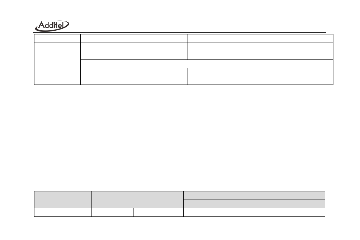
1.3.3 Electrical Output Specifications
Table 4 Electrical Output Specifications
Specifications
Range
Resolution
Accuracy
ADT226
ADT227
Voltage DC
0 to15V
0.1 mV
0.015% RDG + 0.005% FS
0.005% RDG + 0.005% FS
Current DC
0 to 25 mA
0.1 uA
0.015% RDG + 0.005% FS
0.01% RDG + 0.005% FS
Resistance
0 to 400 Ω
1 mΩ
0.015% RDG + 0.005% FS
0.005% RDG + 0.005% FS
0 to 4000 Ω
10 mΩ
0.015% RDG + 0.005% FS
0.01% RDG + 0.005% FS
Page 21
11
Frequency
0.01 to 50000.0 Hz
Auto range, 6-digit
0.005% RDG + 5 on last digit
0.002% RDG +2 on last digit
Voltage mV (TC)
-10 to 75 mV
0.1 uV
0.015% RDG + 0.005% FS
0.0008% RDG + 0.004% FS
Pulse
0 to 9999999
1
N/A
Optional rising edge and falling edge, minimum threshold voltage: 2.5V
Loop power (max
25mA)
24V (226/227)
N/A
±1 V
±1 V
Note 1: When the environmental temperature is (-10~+10) ℃ and (30~50)
℃
, the temperature coefficient is:
(1) Measure of voltage, current, TC and RTD: ±5ppmFS/
℃
.
Note 2: Output characteristics:
(1) Voltage output 0~15V:maximum load current 5mA
,
loading effect 50uV/mA;
(2) Current output 0~25mA
:
maximum open current voltage 24V, drive capacity 1kΩ/20mA, maximum external voltage 50V;
(3) Frequency output: positive square wave, 50% duty cycle, square wave amplitude 0~15V, amplitude accuracy ±0.2%FS, maximum
load current 10mA, supported units: Hz, kHz, MHz, CPM, CPH, s, ms, us;
(4) There are rising edge and falling edge trigger mode available for pulse measure.
(5) TC output
:
maximum load current 5mA, loading effect <5uV/mA;
(6) RTD output
:
maximum excitation current 0~655Ω@2.5mA, 655~4000Ω@0.25mA, 1ms pulse excite supported
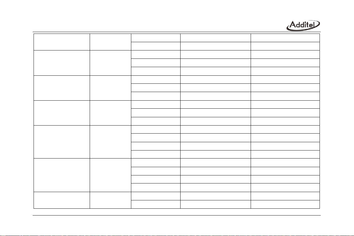
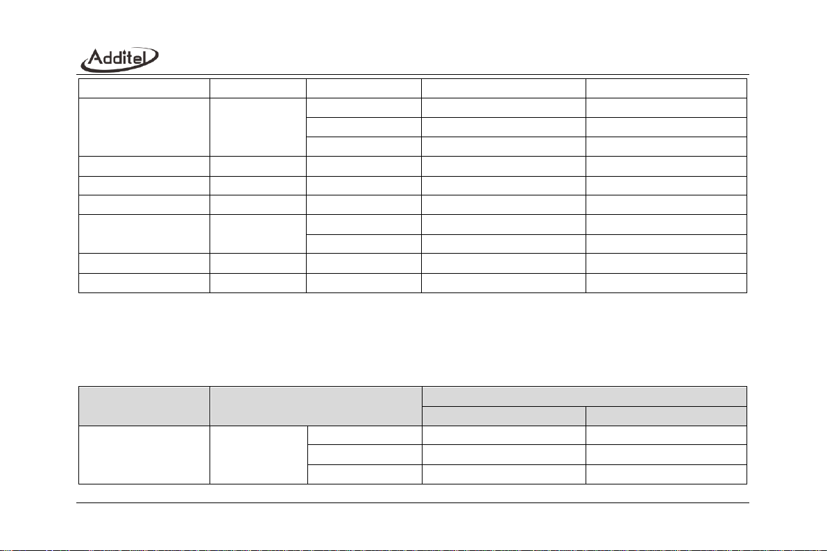
1.3.4 RTD Measurement and Source Specifications
Table 5 RTD Measurement and Source Specifications
Measure and Source
Temperature Range (
℃
)
Accuracy(
℃
)
ADT226
ADT227
PT10(385)
-200~850
-200~200
0.62
0.57
Page 22
12
200~600
0.77
0.67
600~850
0.88
0.75
PT25(385)
-200~850
-200~200
0.29
0.24
200~600
0.40
0.30
600~850
0.47
0.34
PT50(385)
-200~850
-200~200
0.18
0.13
200~600
0.27
0.17
600~850
0.34
0.20
PT100(385)
PT100(391)
PT100(3916)
PT100(3926)
-200~850
-200~200
0.13
0.08
200~600
0.21
0.11
600~850
0.27
0.14
PT200(385)
-200~850
-200~200
0.34
0.32
200~300
0.37
0.34
300~600
0.46
0.41
600~850
0.54
0.48
PT400(385)
-200~850
-200~0
0.17
0.15
0~200
0.21
0.18
200~600
0.30
0.25
600~850
0.37
0.30
PT500(385)
-200~850
-200~200
0.18
0.16
200~600
0.27
0.22
Page 23
13
600~850
0.34
0.27
PT1000(385)
-200~850
-200~200
0.13
0.10
200~600
0.21
0.16
600~850
0.27
0.20
Cu10(427)
-200~260
-200~260
0.59
0.54
Cu50(428)
-200~260
-200~260
0.15
0.11
Cu100(428)
-200~260
-200~260
0.10
0.07
Ni100(617)
Ni100(618)
-60~180
-60~0
0.06
0.05
0~180
0.06
0.05
Ni120 (672)
-80~260
-80~260
0.06
0.04
Ni1000
-50~150
-50~150
0.08
0.07
Note: Compliant with the international temperature scale ITS90. This depends on the maximum tolerance of the RTD measurement and
simulation signal output.
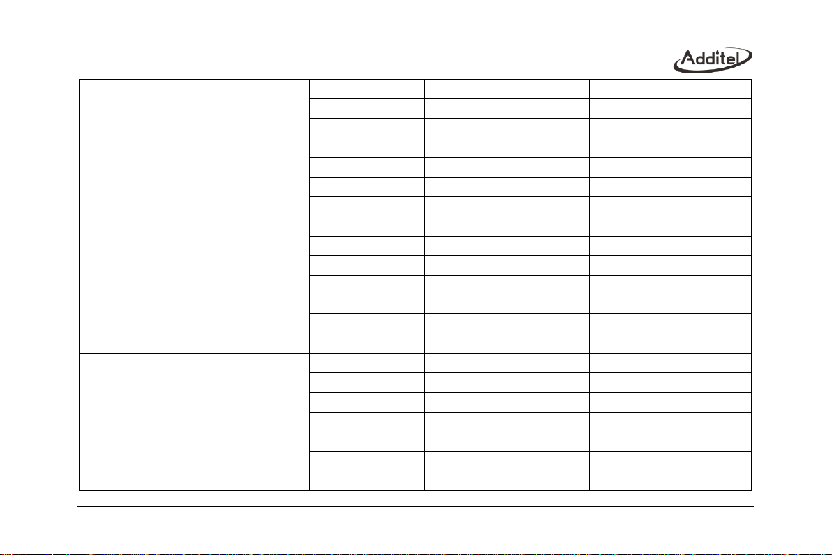
1.3.5 Thermocouple Measurement and Source specifications
Table 6 Thermocouple Measurement and Source Specifications
Measure and Source
Temperature Range (
℃
)
Accuracy(
℃
)
ADT226
ADT227
S
-50~1768
-50~0
0.96
0.76
0~100
0.69
0.56
100~1768
0.64
0.44
Page 24
14
R
-50~1768
-50~0
1.02
0.82
0~200
0.71
0.57
200~1768
0.56
0.38
B
0~1820
200~300
1.89
1.51
300~500
1.25
1.00
500~800
0.78
0.62
800~1820
0.55
0.43
K
-270~1372
-250~-200
0.97
0.72
-200~-100
0.30
0.23
-100~600
0.18
0.12
600~1372
0.35
0.22
N
-270~1300
-250~-200
1.50
1.14
-200~-100
0.44
0.33
-100~1300
0.30
0.19
E
-270~1000
-250~-200
0.54
0.39
-200~-100
0.20
0.15
-100~700
0.15
0.09
700~1000
0.20
0.12
J
-210~1200
-210~-100
0.26
0.19
-100~700
0.15
0.10
700~1200
0.25
0.15
Page 25

15
T
-270~400
-250~-100
0.74
0.55
-100~0
0.15
0.12
0~400
0.11
0.08
C
0~2315
0~1000
0.35
0.24
1000~1800
0.62
0.40
1800~2315
1.02
0.65
D
0~2315
0~100
0.39
0.31
100~1200
0.37
0.25
1200~2000
0.65
0.42
2000~2315
1.03
0.65
G
0~2315
50~100
1.12
0.90
100~200
0.72
0.57
200~400
0.45
0.35
400~1500
0.37
0.25
1500~2315
0.77
0.49
L
-200~900
-200~-100
0.15
0.11
-100~400
0.13
0.08
400~900
0.17
0.10
U
-200~600
-200~0
0.28
0.21
0~600
0.13
0.08
LR
-200~800
-200~0
0.19
0.14
Page 26
16
0~800
0.16
0.10
A
0~2500
0~1200
0.45
0.31
1200~2000
0.78
0.51
2000~2500
1.14
0.74
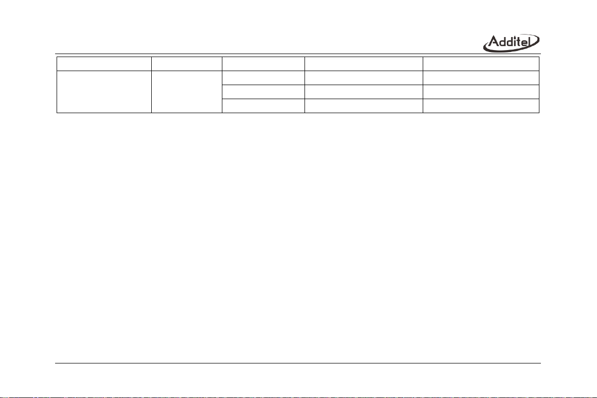
Note: It complies with the international temperature scale ITS90, depends on the maximum tolerance of the TC mV measurement and
simulation signal output.
Page 27
17
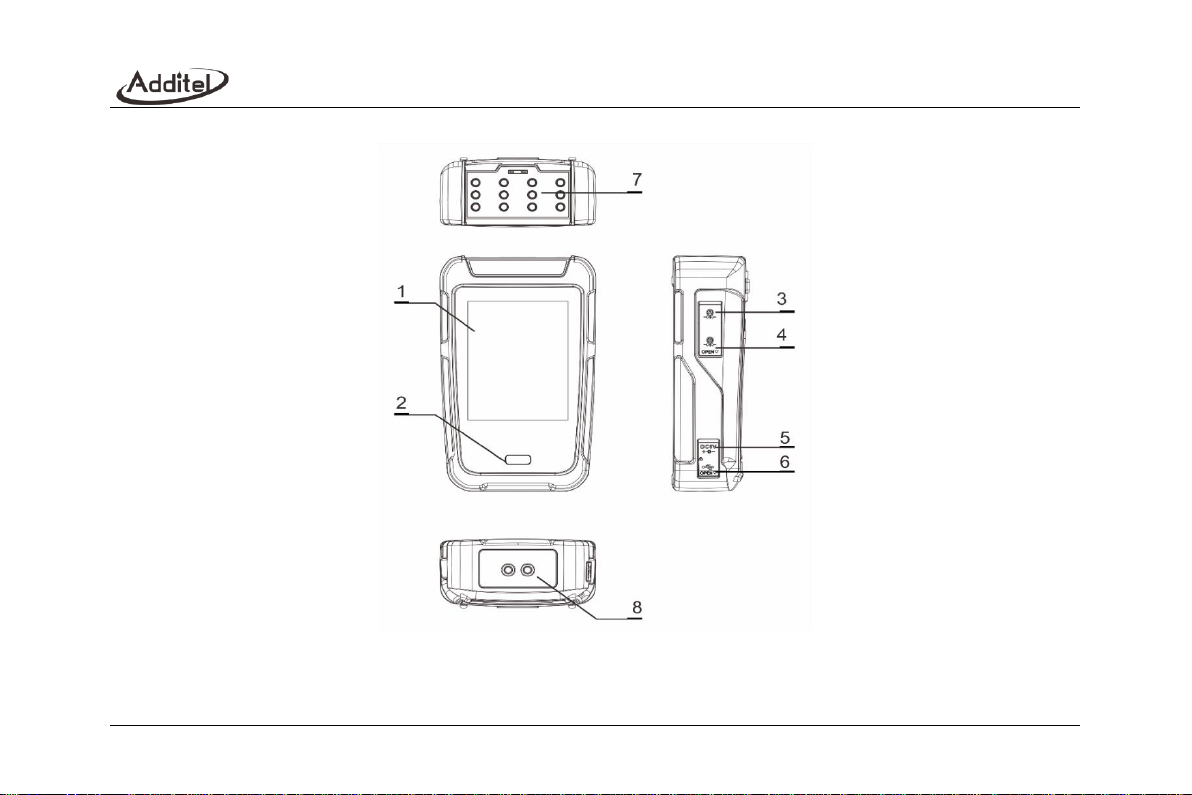
1.4 Basic Structure
Figure 1 Basic Structure
Page 28
18
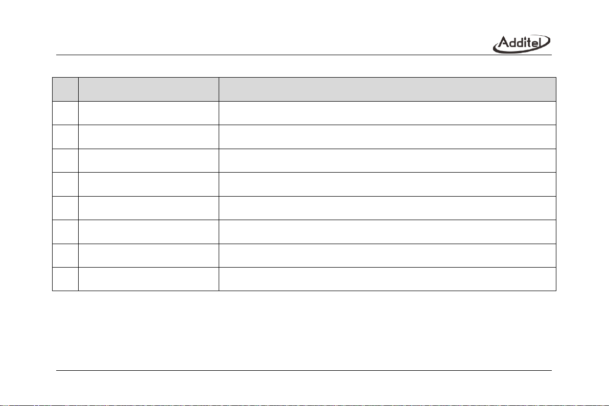
Table 6 Basic Structure
No.
Part Name
Function
1
Display+ capacitive touch screen
Display area, touchable
2
Power key
For switch on/off
3
Lemo type connection B
Connect to external pressure module.
4
Lemo type connection A
Connect to external pressure module.
5
Adaptor port
Power supply from adaptor.
6
USB slave port
For USB communication.
7
Electrical measurement plug
Connection for electrical measurement, including cables and HART communication.
8
AC voltage measure plug
For measuring AC 300V
1.5 Power supply description
By Li-ion battery
Supply the power by 1 pc BP3666A Li-ion battery.
⚫ Li-ion battery is rechargeable by external power independently
Page 29
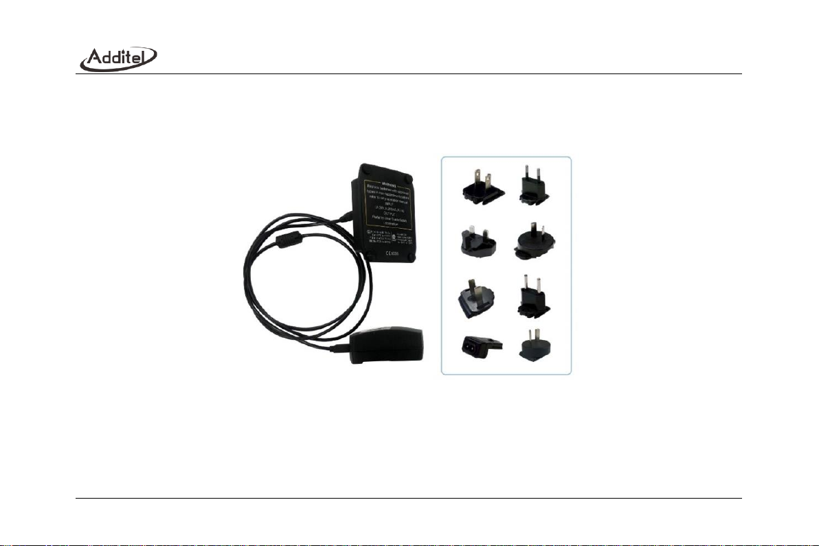
19
⚫ The adapter can quickly adapt to power plugs in various countries
⚫ Do not expose the battery to fire or short circuit the battery
⚫ Only use Additel power adaptors and batteries
Figure 2 Power adaptor
Page 30
20
2. Display and functions
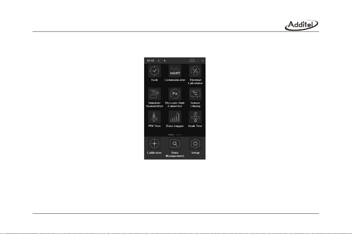
After switching on the device, it will go directly to the Calibrator Function, users can also return to the main page
(see Paragraph 3). The main interface provides access of the functions.
Figure 3 Main interface
2.1 Main interface
In the main interface, there are three sections from top to bottom: status bar, APPs list and main function guide.
(Figure 3: main interface)
1. Status bar: including the time & date, battery, screen lock, external pressure modules, 24V status, Bluetooth,
message center. Note: click the status bar to enter the control center, which provides more view and control items.
Page 31
21
2. APP’s list: shows all the applications provided in the device, including pressure unit converter, leak test, thermal
calculator, communicator, PSV test, sensor library, task, data logger, simulate transmitter, etc.
3. Main function guide: the main function guide at the bottom of the interface provides access to three main functions
of the device: calibrator, data management, system settings.
2.2 Control center
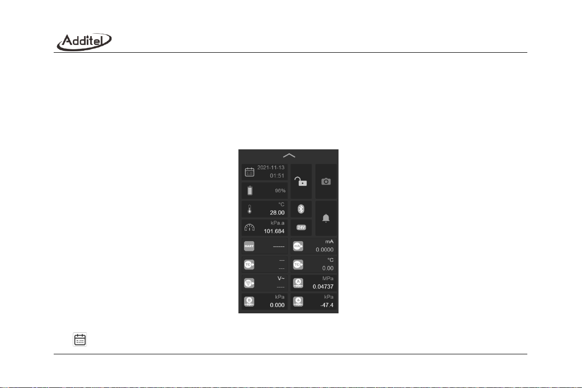
Click the status bar to enter the control center, which provides functions shortcuts and view for information. As shown
in Figure 4.
Figure 4 Control center
: Date and time of the system, click to modify
Page 32
22
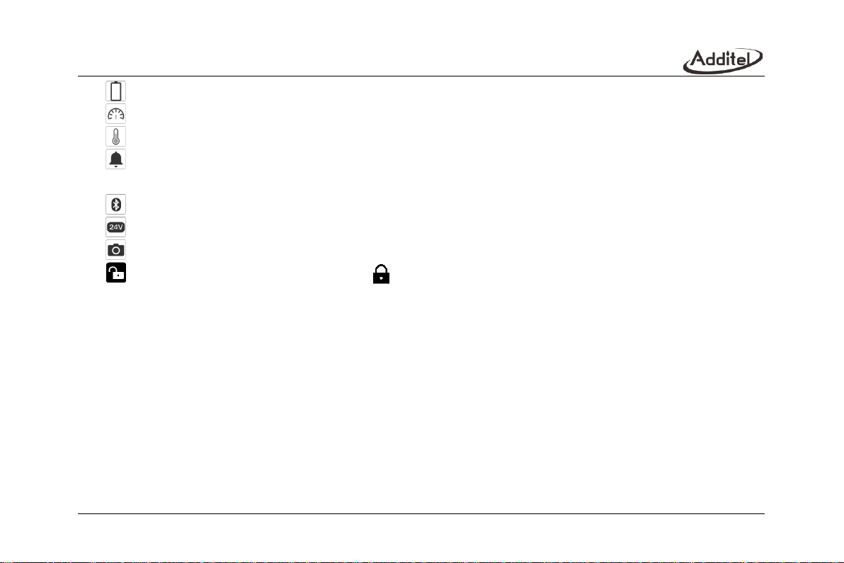
: Battery level, shows battery remaining, plug the adaptor and change the charge mode
: Barometric pressure, click to change its unit
: Internal temperature of the device, click to change its unit
: Message center, there will be a red dot when abnormal, click to enter the message center and show the
abnormal message
: Bluetooth, click to switch on/ off the Bluetooth
: 24V power supply, click to switch on/ off the 24V power supply
: Snapshot, click to take a snapshot
: Screen lock, click to lock the screen. Icon means the screen is locked, operate will be not allowed. Go to
the control center to unlock.
The lower part in the control center displays the signal status of each channel of the calibrator, followed by the
electrical measurement (including HART communication), electrical output, temperature measurement, simulate
temperature output, AC voltage measurement, external channel A (only displayed when the module is connected),
external channel B (only displayed when the module is connected), and differential pressure module channel (displayed
only when the DP module is enabled).
3. Calibrator
Page 33
23
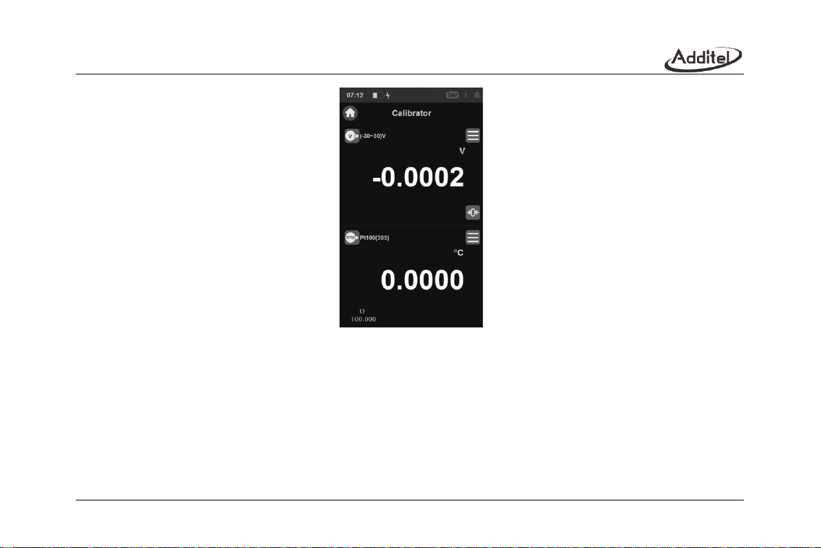
As shown in the Figure 5 of the interface, the ADT227 calibrator can be used to calibrate pressure, loop,
temperature, and flow equipment. The two channels can be displayed simultaneously. Channel 1 (at the top of the
screen) is used for electrical signal measurement, HART, temperature signal measurement and external pressure
module measurement. Channel 2 (at the bottom of the screen) is used for electrical and temperature signal output,
external pressure module measurement. Both channels support a variety of electrical signal types.
The measured or output signal value is displayed in the middle of the individual channel display areas. The icon of
the signal type and the corresponding range information is displayed on the upper left, click this icon to access the menu
for switching the signal type. Click the icon in the upper right corner to set the current channel in the pop-up menu;
Click the icon in the lower right corner to zero the current channel. If the signal type selected in the channel has
multiple values for display (for example, when measuring the TC temperature signal, in addition to the temperature value,
there are also the original millivolt signal value and the cold junction temperature value), the channel will also display
these signal values below the main signal value.
Page 34
24
Figure 5 Calibrator interface
3.1 Electrical Measurement
3.1.1 DC voltage measurement
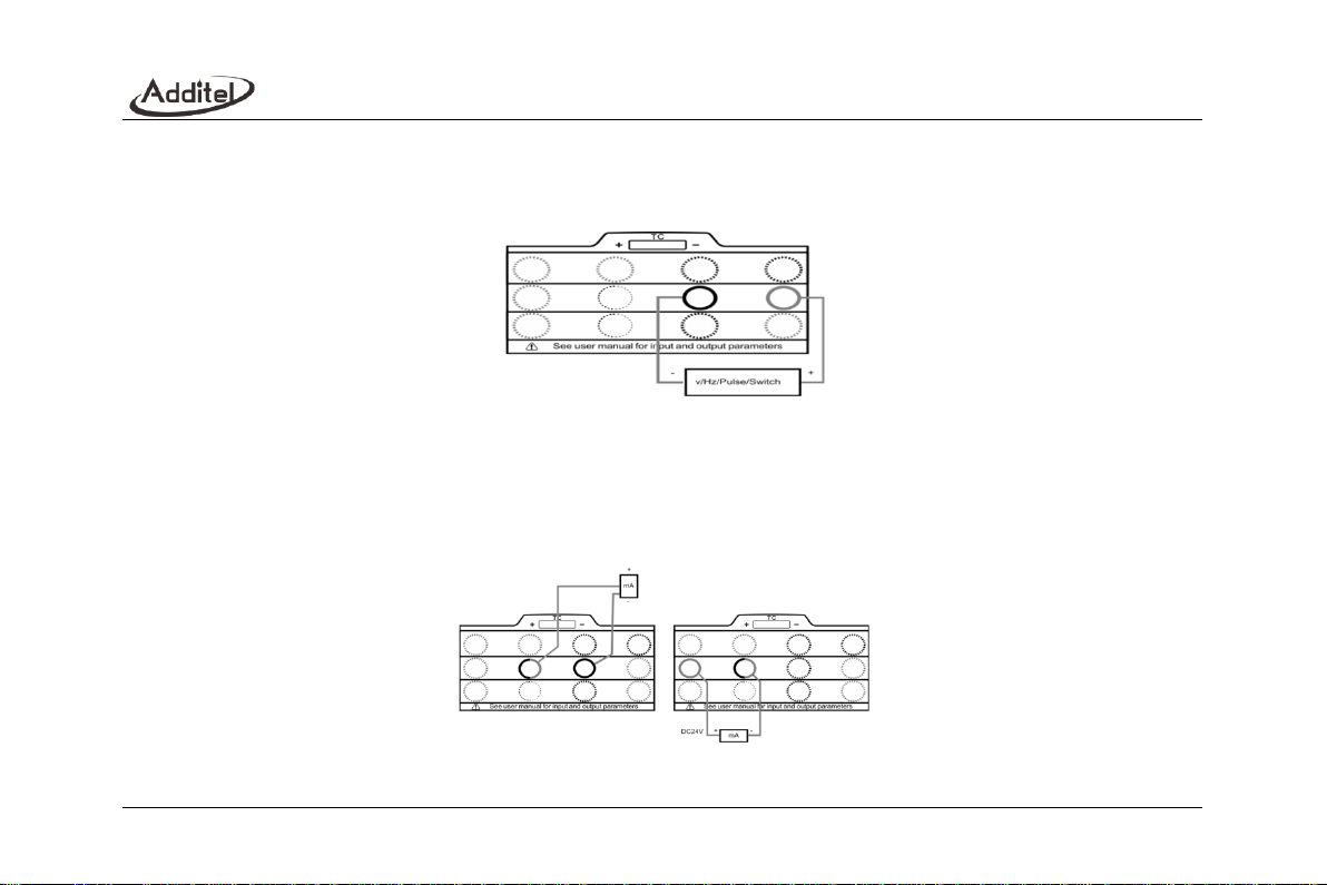
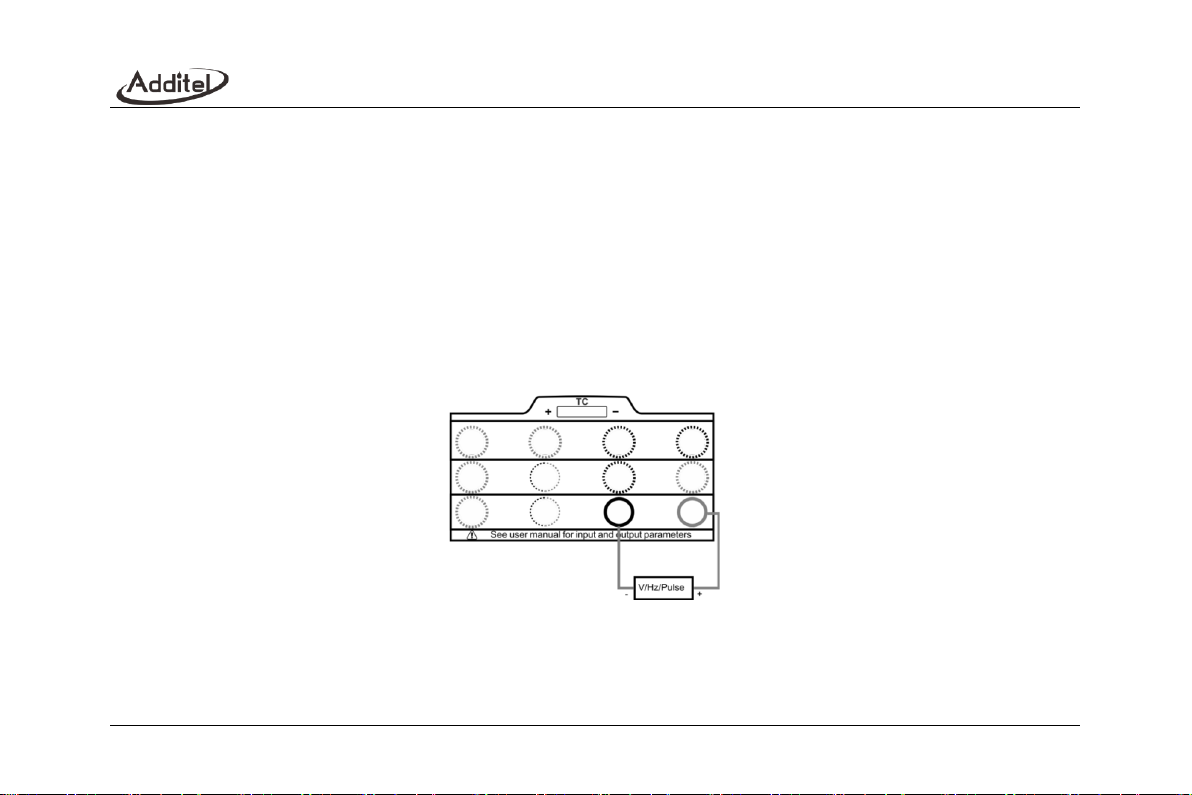
Please connect the leads as shown in the figure (Figure 6 Voltage measurement). Then switch the measurement
signal of channel 1 to voltage measurement.
Page 35
25
In order to ensure the measurement accuracy and adapt to more usage scenarios, two different ranges can be
selected for voltage measurement in channel: (-30~30) V and (-300~300) mV, users should select the appropriate
measurement item according to the use situation.
Figure 6 Voltage/ pulse/ frequency/ switch Measurement
3.1.2 Current measurement
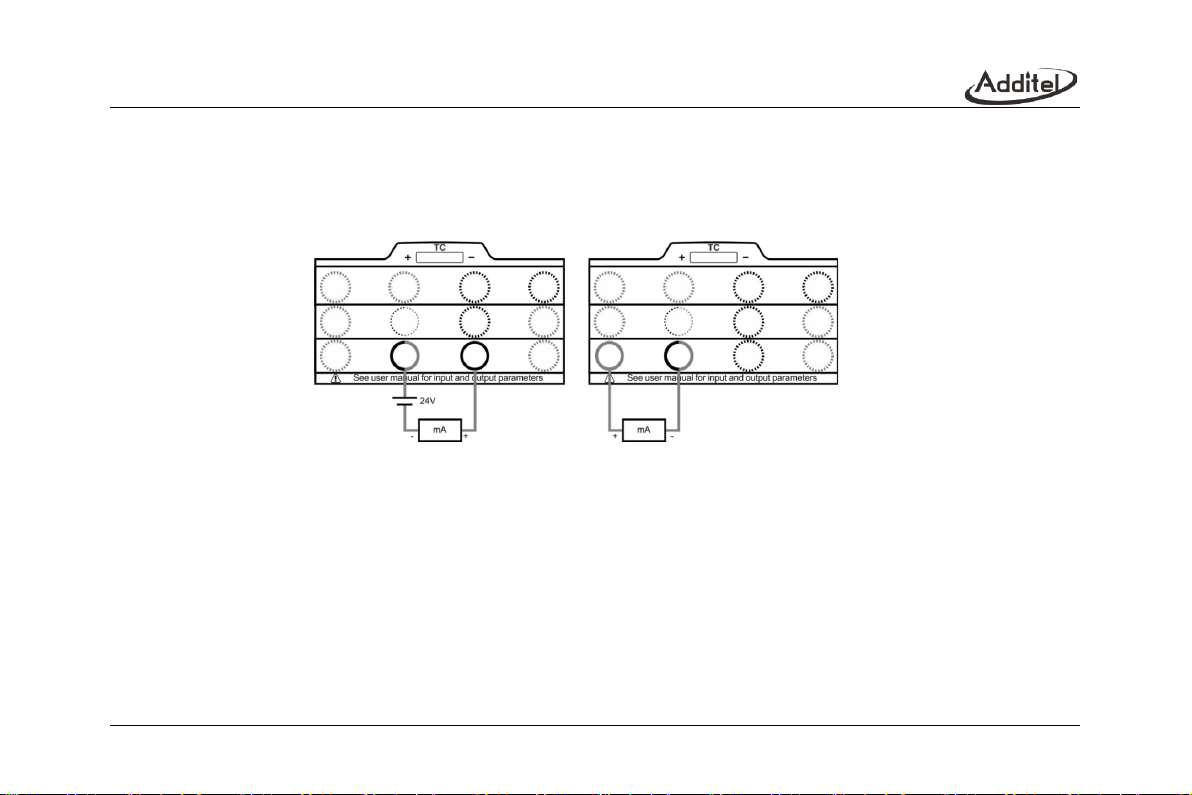
Please connect the leads as shown in the figure (Figure 7 Current measurement). Then switch the measurement
signal of channel 1 to current measurement (-30~30) mA.
Figure 7 Current Measurement
Page 36

26
3.1.3 Switch measurement
The wiring method of the switch measurement function is the same as the voltage measurement, please connect as
shown in the figure 6. Then switch the measurement signal of channel 1 to switch measurement.
The switch measurement also works on channel 2, the calibrator can display the measured value of channel 2 when
the switch action occurs. For example: channel 1 selects switch measurement, channel 2 selects external pressure
module for pressure measure. At this time, when the switch channel detects the on-off state change, it will record the
pressure value of channel 2 at that time. In this case, the device can be used to calibrate a typical pressure switch
device. Click the switch icon in channel 1 and click the "on-off data" option in the channel menu on the right, user can
view the last 10 records in the pop-up on-off data display page.
3.1.4 Pulse measurement
The wiring method of the pulse measurement function is the same as the voltage measurement, please connect as
shown in the figure 6. Then switch the measurement signal to pulse measurement (0 ~9999999) Pulse.
Pulse measurement allows the user to set the pulse counting method. In the pulse measurement mode, enter the
setting menu to select the counting method.
3.1.5 Frequency measurement
The wiring method of the frequency measurement function is the same as the voltage measurement, please connect
as shown in the figure 6. Then switch the measurement signal to frequency measurement (0.01~50k) Hz.
3.1.6 AC voltage measurement
Use the AC voltage measurement port at the bottom of the calibrator to measure the AC voltage, then switch
channel 1 to ACM.
Page 37
27
3.1.7 Scaling
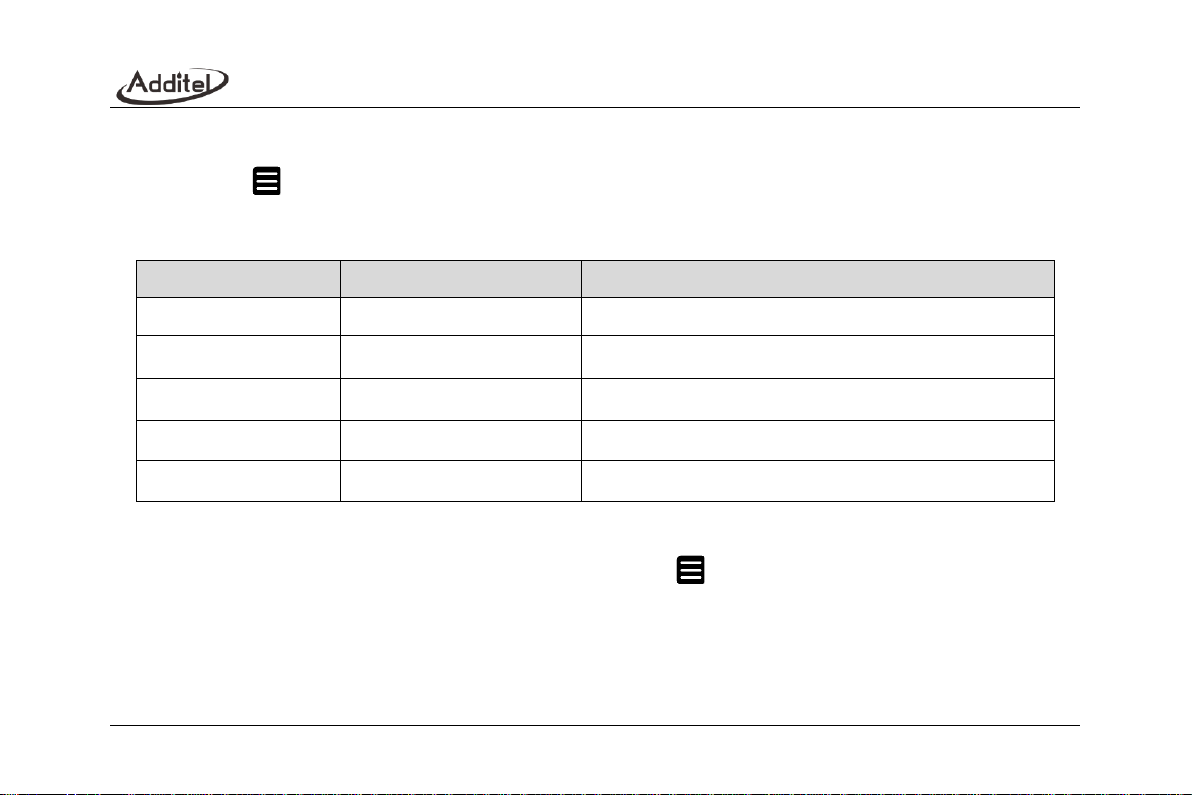
The scaling function gives the calibrator the ability to convert electrical measurement signals into other signals. Click
the menu button of the measurement channel, select the scaling menu item in the pop-up menu, and the parameter
configurations related to scaling will be displayed (see Table 9).
Table 9 Scaling configurations
Subject
Valid Value
Description
Enable/disable
Enable/disable
Enable or disable the scaling function
Input range
(
-9999999~9999999
)
Range before scaling
Output range
(
-9999999~9999999
)
Range after scaling
Resolution
0/0.1/0.01/0.001
The number of decimal places displayed after scaling
Transfer function
Linear, square, or square root
Scaling transfer function
3.1.8 Filter
The calibrator provides two filtering methods: first-order linear filtering and moving average filtering to process data
to meet the needs of different usage scenarios. Click the menu button of the measurement channel, select the filter
menu item in the pop-up menu, and the filter setting interface will be displayed (see Table 10).
Table 10 Filter configurations
Page 38
28
3.1.9 Zeroing
The device provides a short circuit zeroing function for current/voltage signals. this helps to eliminate the zero drift.
The supported zeroing range is 1% FS.
3.1.10 Statistics
Click icon in the channel and select the statistics in the pop-up menu. Then there will be Max, Min and Avg
below the channel 1, click icon to reset the statistics data.
3.2 Pressure measurement
The pressure measurement function is only available when an external pressure module is connected. This
calibrator provides two external module Lemo type connections A and B. When a pressure module is connected to
connection A or B, user needs to select on for measurement. Click the pressure unit above the pressure measurement
value to switch the pressure unit in the pop-up unit selection interface.
Subject
Valid Value
Description
Enable/disable
Enable/disable
Enable or disable the filter function
Method
first-order linear filter or
moving average filter
Filtering algorithm
Filter coefficient
0.01 ~ 1
Only available when the first-order linear filter is selected
Number of samples
1~100
Only available when the moving average filter is selected
De-extremum pairs
0~10
Only available when the moving average filter is selected
Page 39
29
3.2.1 Pressure measurement settings
Click the menu button in the pressure measurement channel and click the "Settings" menu in the pop-up menu
to set the pressure type, resolution, stability, tare, and other functions of the current pressure measurement channel, see
Table 11.
Table 11 Pressure measurement settings
Subject
Valid Value
Description
Resolution
4/5/6
Resolution of current measurement channel
Pressure type
Gauge/absolute
Current measurement channel pressure type
Measurement frequency*
1~10Hz
Data acquisition frequency of the current measurement channel
Stability enable
Enable/disable
Whether to turn on the stability judgment function
Stability value
0.003-1
A value for judging whether the pressure is stable. If the measured
value fluctuates less than this value within the stable time, the
calibrator will judge as stable
Stabilization time
1-60
Time to judge the pressure stability
Tare enable
Enable/disable
Enable or disable tare function
Tare value
(
-9999999~9999999
)
Correction value of the tare function
Tare units
Pressure units
All pressure units
*Note: Only available for some external pressure module.
Page 40
30
3.2.2 Filter
See paragraph 3.1.8.
3.2.3 Module information
The pressure measurement provides a view of the information for the external pressure module, click icon in
the pressure measurement channel, and select module information in the pop-up menu to view the information.
3.2.4 Zeroing
In the gauge pressure mode, when the device is vented, it can be zeroed if there is deviation in the zero point, so as
to eliminate the zero drift. The supported zero range is 1% FS.
3.2.5 Statistics
See paragraph 3.1.10.
3.3 Temperature measurement
The calibrator supports thermocouple (TC) and thermal resistance (RTD)
temperature measurement.
3.3.1 Thermocouple measurement
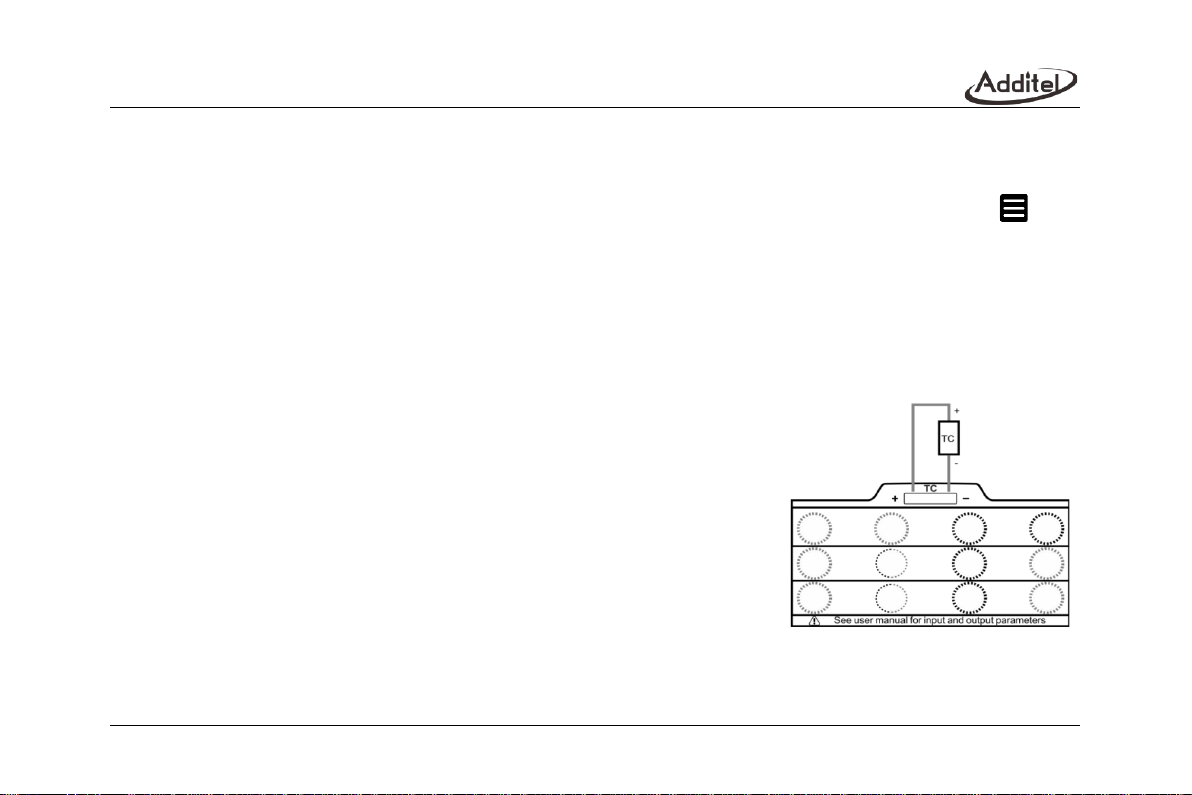
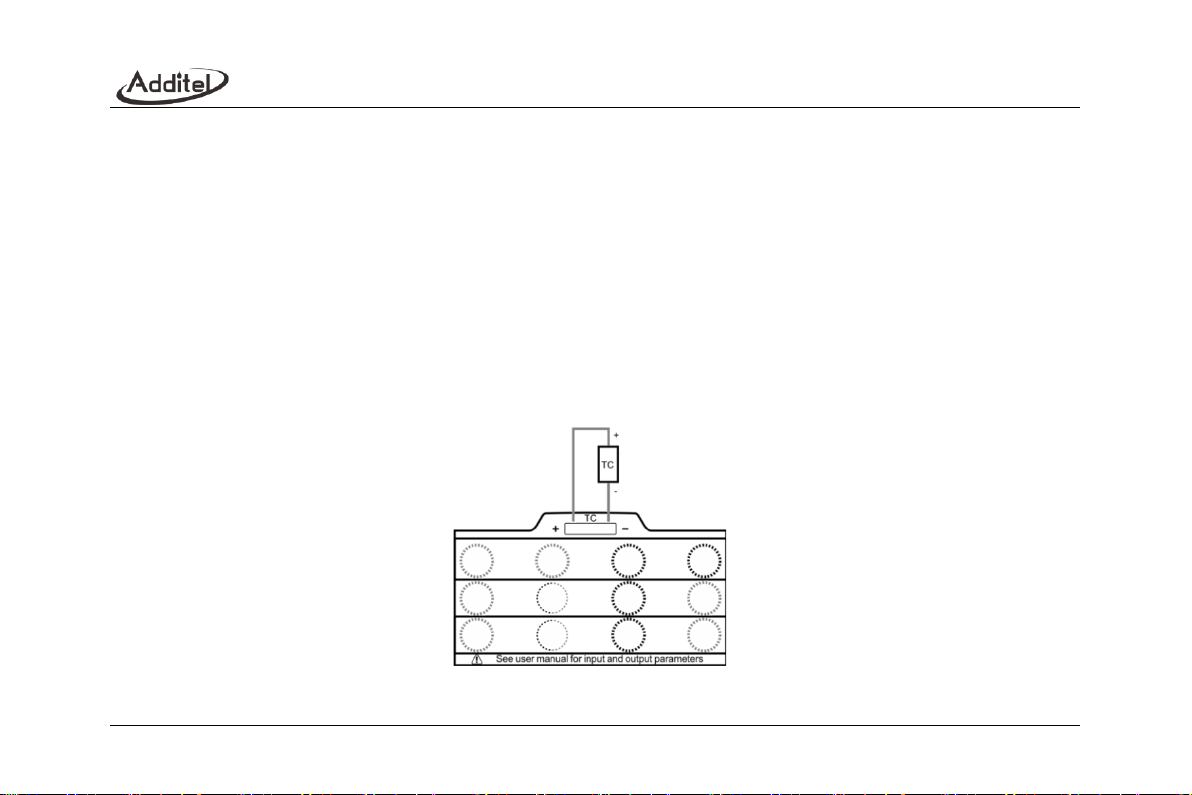
The connection configuration for a thermocouple measurement is shown in
the Figure 8 Thermocouple measurement. Once connected, switch the
measurement signal of channel 1 to TC measurement.
Figure 8 Thermocouple measurement
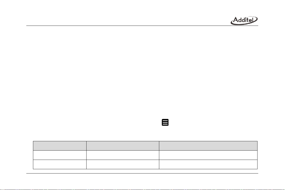
Page 41
31
3.3.2 Thermocouple settings
Click the "Setup" button of the thermocouple measurement channel to set various parameters for the thermocouple
measurement function, see Table 12.
Table 12 TC settings
Subject
Valid Value
Description
Sensor type
mV/ All supported TC types
Select the type of thermocouple sensor
Cold junction type
Int/Ext/Custom
Select the cold junction compensation method, Int means to use
the built-in cold junction sensor of the calibrator. Ext is the
external CJC to be fixed at a value and custom is based on an
external sensor measurement.
Ext CJC value
-80~300
Set customer value for the cold junction compensation value,
only available when user selects fixed as the cold junction type
Temperature unit
K / ℉/ ℃
Temperature unit selection
Resolution
0/0.1/0.01/0.001
Temperature display resolution
Page 42
32
3.3.3 RTD measurement
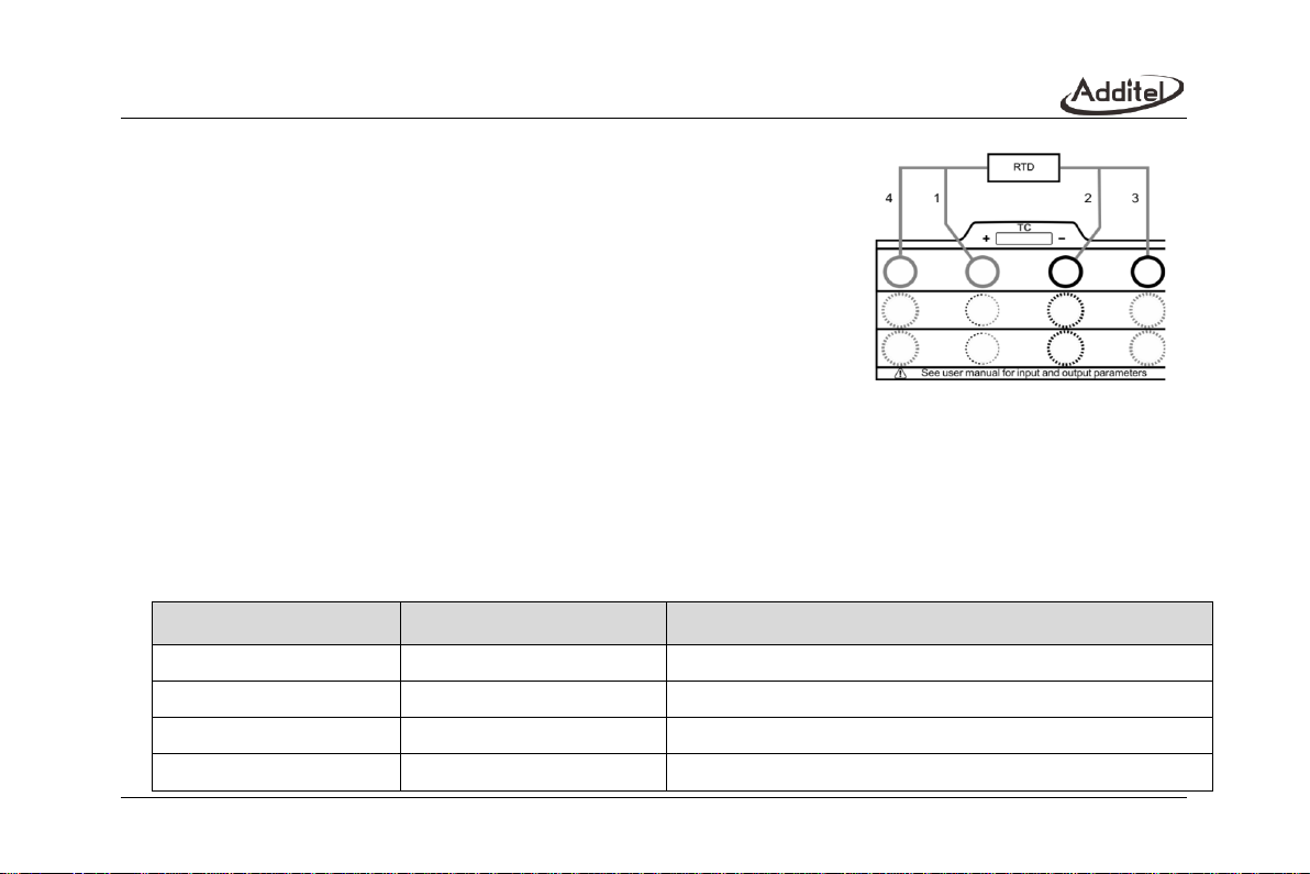
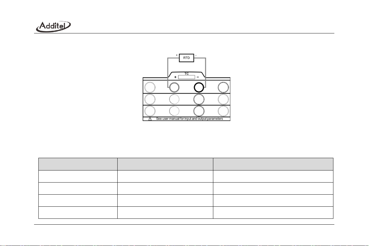
The connection configuration for an RTD measurement is shown in the
Figure 9, RTD measurement. Once connected, click the channel setup icon
and select the RTD measurement.
3.3.4 RTD settings
Click the "Setup" button of the RTD measurement channel to set various parameters for the RTD measurement
function. See Table 13.
Table 13 RTD measurement settings
Item
Valid Value
Comment
Sensor type
Ω/All supported RTD types
Select the type of thermal resistance sensor
Wires
2/3/4
Select the RTD wire
Scale
400Ω/4000Ω
Available for Ω sensor
Temperature unit
K / ℉/
℃
Temperature unit selection
Figure 9 RTD measurement
Page 43
33
Resolution
0/0.1/0.01/0.001
Temperature display resolution
3.3.5 Zeroing
See paragraph 3.1.8.
3.3.6 Statistics
See paragraph 3.1.10.
3.4 HART calibration
The device provides HART bus communication, using the simplified DD file, provide general settings, service and
calibration for HART temperature and pressure transmitters. It is recommended to read the transmitter’s manual before
use.
Note: the calibrator will always be the master during communicating with the HART device. In order to avoid harm to
the controlling system, please separate the HART device from the controlling system before connecting the calibrator
with the HART device.
Page 44
34
3.4.1 Search and connection
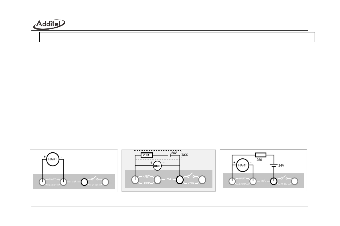
Switch to HART on the Calibrator page, the calibrator will automatically use the last selected power supply
configuration (default is the internal resistance and internal source), and search for the address "0". After searching for
the HART device, it will automatically connect and display its value. Click the menu icon to select search or click the
HART measurement channel screen when the HART device is not connected to enter the HART power supply
configuration interface. The configuration provided by the calibrator is as Figure 10, 11 and 12.
After selecting the configuration, go to the search interface. Start searching for HART devices from address "0", if
the search is success, it will stop searching and display the HART device list and main information, otherwise the
calibrator will start searching from address "1" until address "15", After completing the search, the calibrator will list all the
searched HART devices, and can display up to 15 HART devices at the same time.
3.4.2 HART Setting
In the Calibrator page, switch to HART channel and click icon to go to the settings, including device
information, sensor information and device output, see Table 14.
Table 14 HART settings
Subject
Parameter
Description and valid value
Device
information
Label
Support letter, symbol and number, the length cannot be greater than 8 characters
Date
Any date supported by transmitter
Information
Support letter, symbol and number, the length cannot be greater than 32 characters
Description
Support letter, symbol and number, the length cannot be greater than 16 characters
Figure 12 External source + external resistor
(supports loop current measurement)
Figure 11 External source + external resistor
Figure 10 Internal source + internal resistor
Page 45
35
Final Assembly Number
Support integer, the length cannot be greater than 8 characters
Preambles
Integer 5~20
Manufacturer
Read only
Device type
Read only
Device ID
Read only
Write-protect
Read only
Universal Version
Read only
Software Version
Read only
Hardware Version
Read only
Device Version
Read only
Sensor*
Sensor S/N
Read only
Sensor unit
Read only
Sensor lower limit
Read only
Sensor upper limit
Read only
Sensor minimum scale
Read only
Device
output
Process Variable/Range
Units
Can be changed to any unit supported by transmitter, the upper/ lower limit are along
with
Lower Limit of PV Range
Cannot exceed the sensor lower limit
Upper limit of PV Range
Cannot exceed the sensor upper limit
Transfer Function
Linear or square root
damp
Data filter time, unit is S
Page 46
36
Poll Address
Default 0, integer 0-15
Burst Mode
Enable or disable, depends on the transmitter
Burst Command
Set burst command
Alarm State
Read only
Note: The temperature transmitter can provide additional setting items such as sensor type, wires, sensor status, CJC type and
value according to the function supported by the transmitter.
3.4.3 Process variables
In the HART page choose electrical measurement, click icon and choose Process variables, it can show
process variables, output current, percentage, second variable, third variable and loop current. Among these, the units of
second and third variable depend on different devices.
3.4.4 Diagnosis/ Service
1. Current loop test
♦ Click the icon to select Diagnosis/ Service and enter the current loop test. Conduct the current loop test, the
value range of this parameter is (4-20) mA.
♦ The HART measurement value at the top of the calibrator page is the real value of the current loop.
2. Zeroing (only for pressure transmitter)
♦ Select zeroing in the HART Diagnosis/ Service interface to enter the zeroing interface.
♦ Ensure that the current measured value is close enough to the zero point, otherwise it may cause zero failure.
Page 47

37
3. Current Adjustment
♦ By adjusting the scaling coefficient of current output of the transmitter, the output current value of the transmitter will
maintain the same as the actual loop current output value.
♦ It provides adjustment of D/A zero point (4mA) and D/A full scale (20mA): press the screen to get the value for
adjustment.
4. Sensor adjustment
♦ The Sensor adjustment is used to adjust the PV of the transmitter, usually including one or two adjustment points
(lower point and upper point). Some transmitters do not support this function (please refer to the transmitter's
manual).
♦ Lower point adjustment
(1) First, provide the external standard source to the transmitter manually. After stabilized, input the standard source
display value directly by the number keys; For the pressure transmitter, the standard source display value can be
directly obtained through the external pressure module. In this case, click the Get icon on the calibration page to
get the standard value of the pressure module directly.
Page 48

38
Note: For some transmitters, it is not necessary to input the adjustment value, the transmitter automatically uses the upper and
lower limits of the range (the lower limit of the range corresponds to the lower point adjustment value, and the upper limit of the range
corresponds to the upper point adjustment value) as the adjustment value. In this case, just input any value;
(2) Execute the Trim command. After that, the PV value will change according to the trimmed point value.
♦ Upper point adjustment
Same as the lower point adjustment.
♦ Single point adjustment
Same as the lower point adjustment.
♦ Restore to factory setting
After selecting "Restore Factory", a dialog box will appear "Are you sure you want to perform this operation?", click
OK to continue. After that, the transmitter's lower and upper point values will be restored to the factory settings.
Note: The current loop test and D/A adjustment is only available when the transmitter address is 0.
Note: The sensor adjustment provides corresponding support items according to the transmitter function.
Note: If the HART transmitter used does not have all the above functions, contact the manufacturer.
Page 49
39
3.5 Output
The calibrator provides a variety of electrical signal output and analog temperature output functions to cope with
various usage scenarios and different devices under test.
The output function of the calibrator not only supports manual setting of set points for signal output, but also
provides two automatic output functions: automatic ramp output and automatic step output, and two convenient manual
output functions: manual step output and manual fine-tuning output.
3.5.1 Voltage output
The connection configuration for an output of voltage, frequency or pule is shown in figure 13. Once connected,
click the channel setup icon and select (0-15V).
Figure 13 Voltage, frequency, pulse
output
Page 50
40
3.5.2 Current output
The connection configuration for an output of voltage is shown in the Figure 14. Once connected, click the channel
setup icon and select the (0~25)mA .
3.5.3 Frequency output
The connection configuration for a frequency output is shown in the Figure 13 Voltage, frequency, pulse output.
Once connected, click the channel setup icon and select the (0.01~50k)Hz.
The frequency output function provides a setting menu, in which the amplitude of the frequency output can be set.
Figure 14 Current output
Page 51
41
3.5.4 Pulse output
The wiring method of using the pulse output function is the same as the voltage output (Figure 13
voltage/frequency/pulse output). After connecting as shown in the figure 14, click the channel menu of channel 2 to
collapse it and select (1~9999999). The pulse output option provides a setting menu, and the amplitude and frequency of
the pulse output can be set in the setting menu.
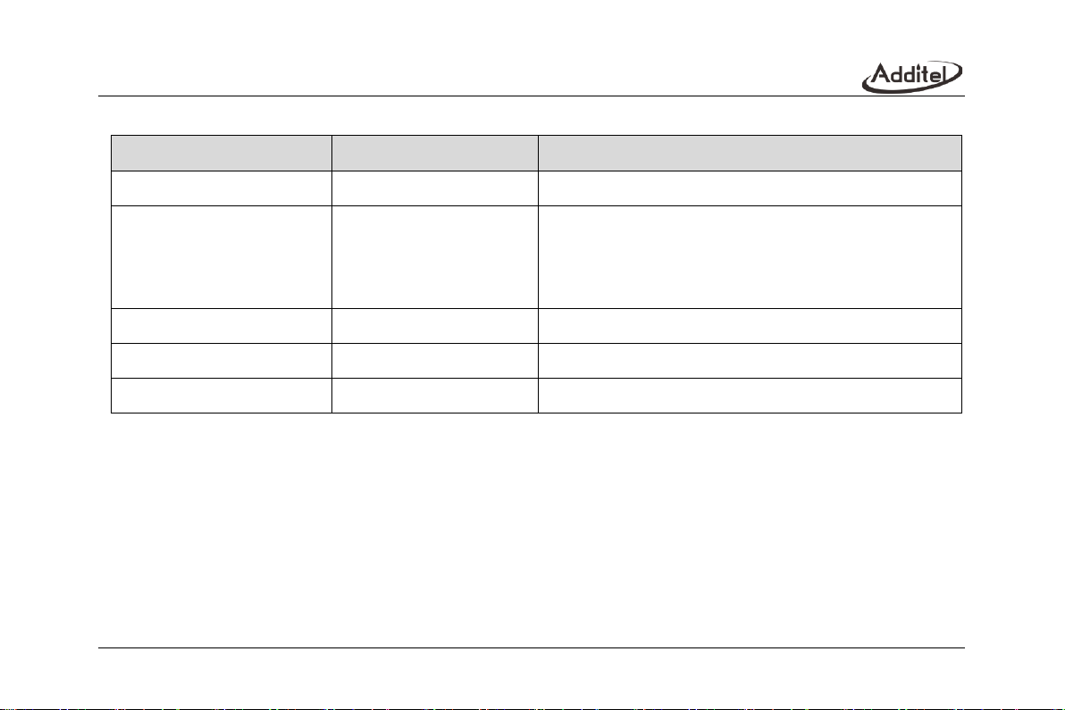
3.5.5 Simulate Thermocouple (TC) output
The wiring method of simulating TC output is shown in the figure (Figure 15 Simulate thermocouple output). After
connecting as shown in the figure 15, click the channel menu icon of channel 2 and select the TC output to use the
simulate thermocouple output function.
Click the "Settings" menu item in the simulate TC output menu to enter the simulate TC setting menu. The setting
menu provides a variety of settable parameters for the simulate TC output function, see Table 15.
Figure 15 Simulate Thermocouple Output
Page 52
42
Table 15 TC Output Setting
Subject
Valid Value
Description
Sensor Type
mV/ TC sensor
Select sensor type
Cold junction type
Int/Ext/Custom
Select cold junction(CJC) type, Int means internal CJC, Ext
means external CJC, custom means an external sensor
providing a measurement.
CJC value
-80~300
Available when the cold junction type is Ext
Temp Unit
K / ℉/ ℃
Select the temperature unit
Decimal digits
0/0.1/0.01/0.001
Decimal accuracy of temperature display
3.5.6 Simulate RTD output
The wiring method of an analog thermal resistance output is shown in the figure (Figure 16 simulate RTD output).
After connecting the wiring as shown in figure 16, click the channel menu for channel 1 and select the RTD to use the
simulate RTD output function.
Click the "Settings" menu item in the menu of the simulate RTD to enter the simulate RTD setting menu. The setting
menu provides a variety of settable parameters for the simulate RTD output function.
Page 53
43
Figure 16 Simulate RTD Output
Table 16 RTD Output Settings
Subject
Valid Value
Description
Sensor Type
Ω/RTD sensor
Select RTD sensor
Scale
400Ω/4000Ω/ Auto
Available for sensor type Ω
Temp. Unit
K / ℉/ ℃
Select the temperature unit
Resolution
0/0.1/0.01/0.001
Decimal accuracy of temperature display
Page 54
44
3.5.7 Set point output
Click the signal output value in channel 2 of the calibrator and input the set point value you want to output in the pop-
up set point input keyboard and click the confirm button to set the output value of the current option.
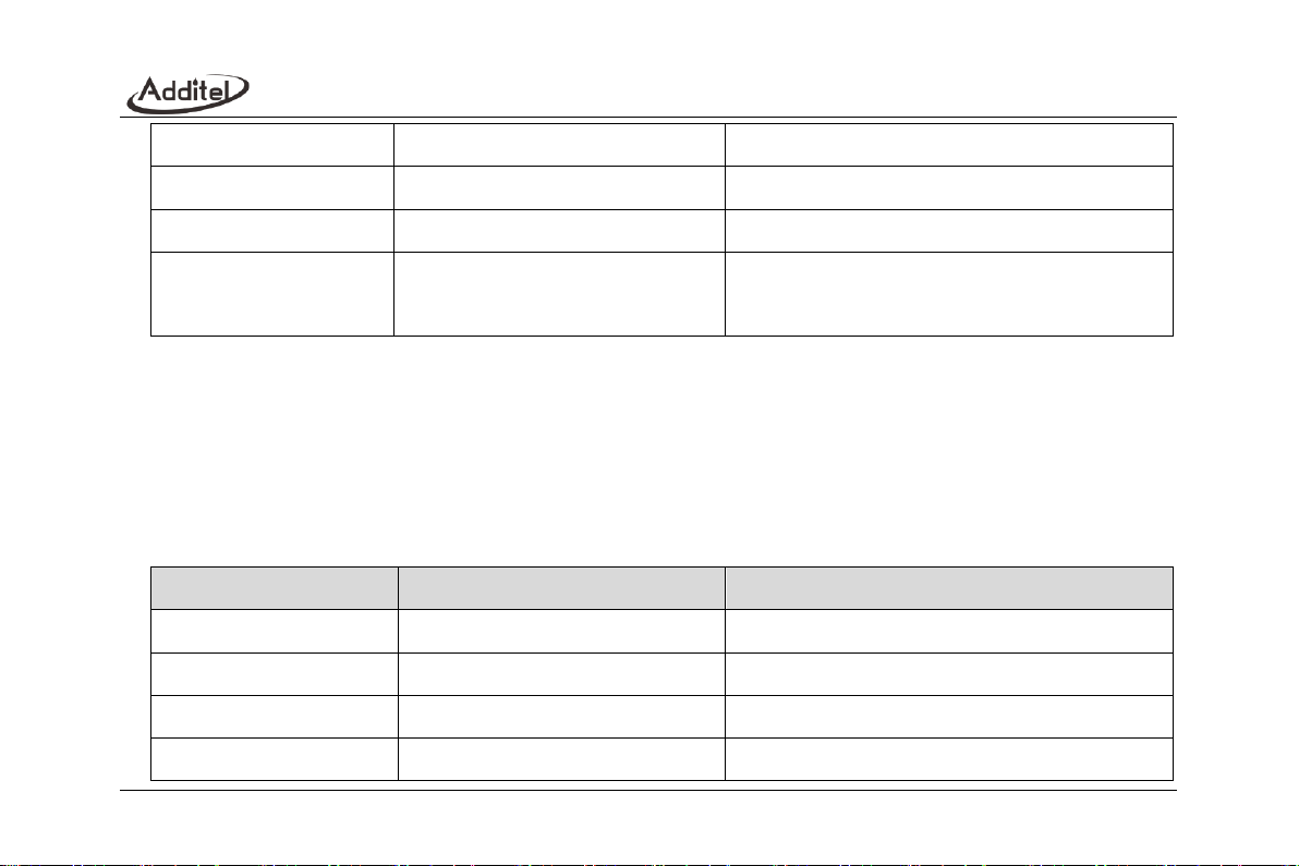
3.5.8 Ramp output
The three electrical settings of voltage, current, and frequency of the calibrator, and the two simulate temperature
output options of, simulate thermocouple and simulate thermal resistance, all support automatic ramp output mode. The
Ramp can increase or decrease the output value smoothly and continuously. In fact, a small step value is used to form a
Ramp signal, which is represented by a Ramp gradient in the calibrator. The calibrator will automatically calculate the
Ramp gradient according to the start and end values of the Ramp and the rise and fall time. When the start value and
end values are fixed, the longer the ramp time, the slower the ramp output and the smaller the ramp gradient.
A complete ramp output stroke includes an up stroke (from the start value ramp to the end value) and a down stroke
(from the end value ramp to the start value), when the rise time and fall time are the same, the actual output points of the
up stroke and the down stroke are symmetrical one by one. Click icon to select ramp output and go to the settings,
as shown in Table 17
Table 17 Ramp Output Settings
Subject
Valid Value
Description
Range
Numbers
Ramp start and end value
Rise time
(1~999999)
Up stroke run time
Page 55
45
Fall time
(1~999999)
Down stroke run time
High point dwell
(0~999999)
High point dwell time
Low point dwell
(0~999999)
low point dwell time
Cycle index
(0~100)
Ramp cycle index (a complete up and down stroke is a
cycle), if this item is set to 0, it means an infinite cycle.
3.5.9 Automatic step output
The three electrical channel settings for voltage, current, and frequency of the calibrator, and the two simulate
output options all support automatic step output mode. In the automatic step output mode, the calibrator outputs signals
in sequence according to the output points set by the user. The automatic step function provides flexible setting items to
control the step output behavior and create different types of output points. As shown in Table 18.
Table 18 Automatic step output settings
Subject
Valid Value
Description
Stroke type
One way/ round
Select stroke type
Cycle times
(0~100)
Automatic step cycle times, if set 0, it means infinite loop
Cycle interval
(0~999999)
Interval time between cycles
Dwell time
(0~999999)
Dwell time between step points
Page 56
46
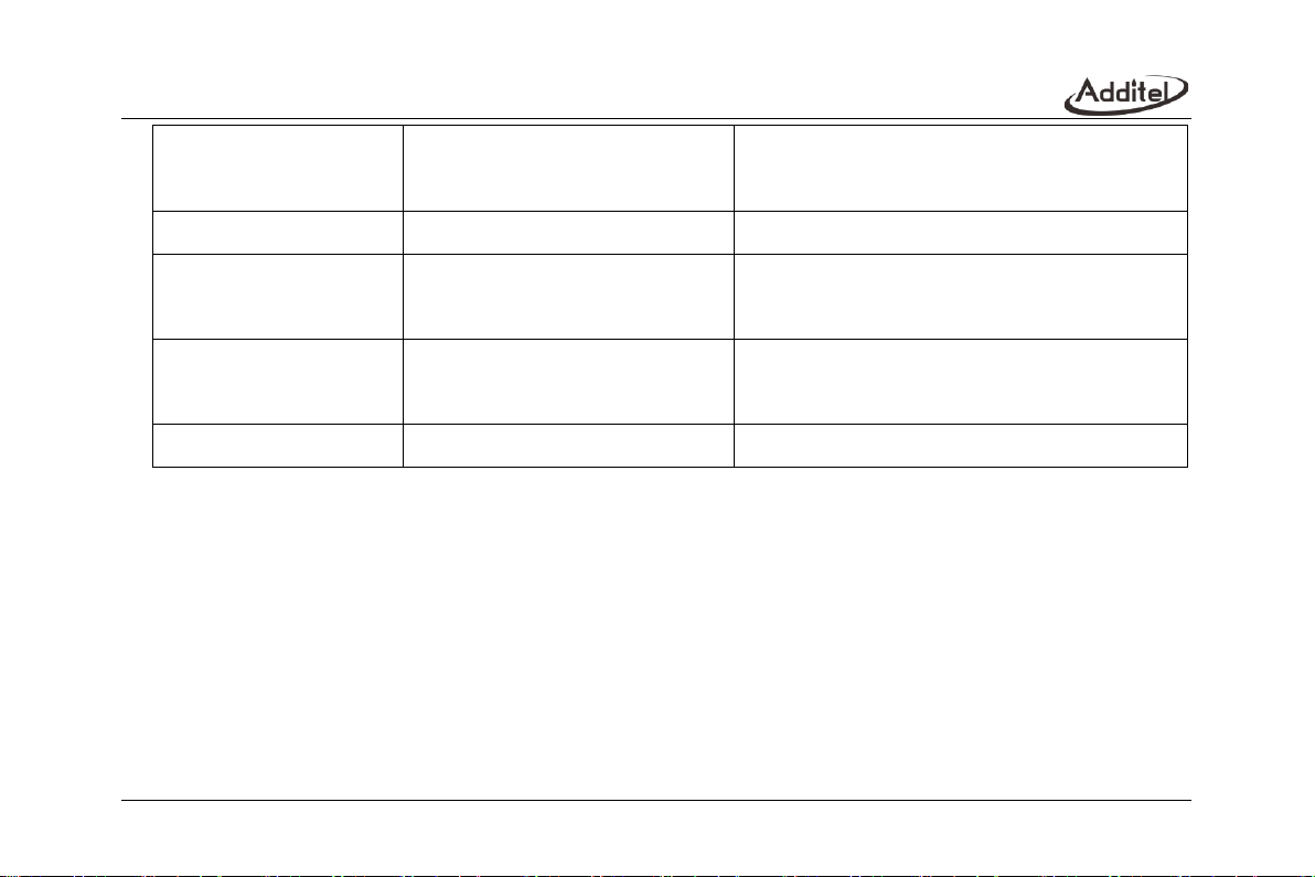
Step mode
Step point/ percentage/ engineering
unit/ custom
Select step mode
Number of step points
(2~16)
Number of step points, available for Step point mode
Step size
Percentage: 7~100
Engineering unit: dynamic range
Step size, available for percentage/ engineering unit
Step point list
Step point
Add or delete set points, available for custom step
mode
Scale
Numbers
Lower and upper point of the automatic step scale
3.5.10 Manual step output
The current, voltage and frequency output, along with the simulate TC, simulate RTD of the calibrator, can all
provide an output using the manual step function. Open the settings menu of the corresponding types in the above list
and click the "Manual step" menu item to enter the manual step mode. The manual step mode allows users to customize
the manual step output range, and output according to any percentage step. Click the left or right button under the
channel to adjust the output value according to the current set step.
Click the step range value in the middle of the left and right buttons under the channel to pop up the range input
interface, where the user can customize the output range of the manual step, and the customized step output range
cannot exceed the output range of the current signal type.
Page 57
47
The step length setting menu button of manual step is at the bottom right of channel 2, click this button to select
the step length of 25%, 100%, or manually input a custom step length by the user.
Click the button at the top right of channel 2 to exit manual step mode.
3.5.11 Fine adjustment output
The current, voltage, frequency and simulate temperature outputs of the calibrator can all be used in the fine-
adjustment output mode. In the above configurations, open the settings menu of the corresponding configuration and
click the "fine adjustment" menu item to enter the fine adjustment output mode. In the fine-adjustment output mode,
users can adjust the output value bit-by-bit as needed to achieve the purpose of fine-adjustment the output value.
In the fine-adjustment mode, click the value in the middle of the channel to move the cursor, and click the up and
down icon on the right side of the channel to adjust the value of the current cursor position. In the process of
adjusting the output value using the fine-tuning output mode, the output value cannot exceed the output range of the
current signal type. Click the icon on the upper right of channel 2 to exit the fine-tuning output mode.
Page 58
48
4. System settings
On the main screen of the device, click the icon in the right bottom to enter the system setting interface. It
includes Bluetooth, power management, system calibration, services, personalization, and product information.
4.1 Bluetooth communication
The calibrator includes Bluetooth communication. Click the "Bluetooth Communication" menu item in the system
settings interface to enter the Bluetooth communication setting interface. The Bluetooth communication setting interface
provides the enabling and disabling of the Bluetooth communication function and the query function of the Bluetooth
device name and physical address.
4.2 Power management
4.2.1 Brightness
Change the LCD’s brightness by adjusting the brightness bar.
4.2.2 Battery information
Show the current battery connection status and information.
4.2.3 Auto backlight off
◆
The backlight turns to lowest automatically after a certain period of time that no keypad operation and communication.
◆
Supported durations of: Never, 30s, 1 min, 5mins, 15mins and 30mins.
◆
After the backlight closed, the first press to the keypad will only activate the backlight, only after this can the press
takes effect.
Page 59

49
4.2.4 Auto sleep after backlighting goes off
◆
The backlight turns off after the set time has exceeded with no keypad and communication activity. At this time, the
automatic timing to sleep mode starts, then the calibrator will go to sleep.
◆
Supported durations of: Never, 1min, 5mins, 15mins and 30mins.
◆
When using AC adapter, the calibrator cannot auto sleep.
◆
This function will be invalid when performing Pressure control, Auto step or Task.
◆
The Auto sleep will be invalid when the Auto backlight off is set to Never.
4.2.5 Auto power off after sleep
◆
The backlight will be turned off if there is no keypad or communication activity within the set time, and the automatic
shutdown timer will start after the start of sleep. After reaching the set time, the automatic shutdown will take effect.
◆
Supported duration of: Never, 5mins, 15mins, 30mins, 1hour and 2hours.
◆
When using AC adapter, the calibrator cannot auto power off.
◆
This function will be invalid when performing Pressure control, Auto step or Task.
◆
The Auto power off will be invalid when the Auto backlight off is set to Never.
4.3 Services
4.3.1 Calibration
Click the " Calibration" menu item in the service interface and enter the calibration password "123456" in the pop-up
password input box to enter the system calibration interface. In the system calibration interface, you can calibrate all the
measurement and output signals in the device. The calibration process is as follows:
Page 60

50
1. Select the signal to be calibrated in the signals list.
2. Use a high-precision reference, after fully warming up, follow the calibration guide in the interface and click the "Start"
button to start the calibration.
3. According to the reference calibration point provided on the interface, select the appropriate standard value, and enter
it.
4. Click the "Finish" button to send the calibration data to the module to complete the calibration.
5. Click the "Restore to factory data" button at the bottom of the calibration interface to restore the factory calibration data
of the device. Click the “Cancel Zero" button below to clear data of the current readings.
4.3.2 Maintenance
Enter the password for this function, default password is 123456.
◆
Maintenance record: view and edit maintenance information.
◆
Calibration record: view the calibration history.
◆
Pressure module overpressure record: view the pressure module overpressure information.
◆
Operation information: view barometric pressure, mainboard, and battery information.
4.3.3 4.3.3 Restore to factory data
Enter the password for this function, default password is 123456.
◆
Restore to the factory data will not restore the system calibration data.
4.4 Personalization
4.4.1 Sound
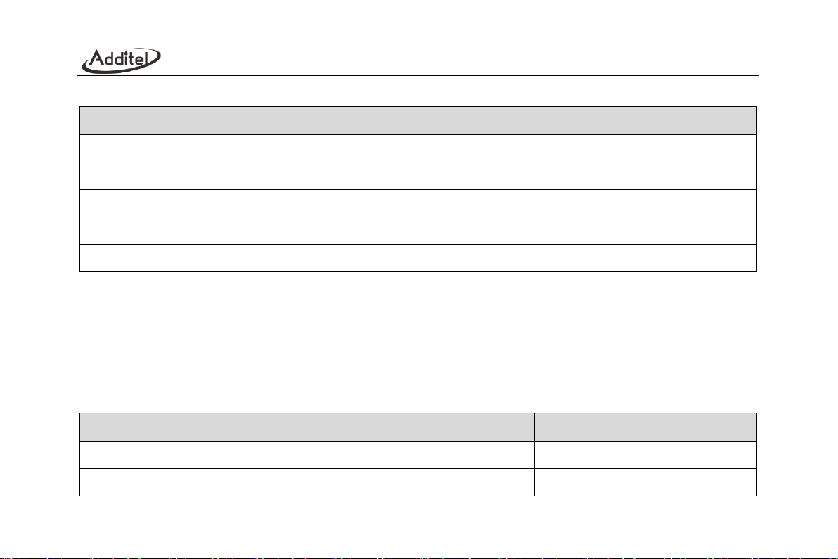
Change the sound level by adjusting the volume bar. It also provides a sound configuration feature. see Table 19.
Page 61
51
Table 19 Sound settings
Subject
Valid Value
Comment
Touch sound
On / Off
Touch sound setting
Prompt sound
On / Off
Prompt sound setting
Over range sound
On / Off
Over range sound setting
Snapshot sound
On / Off
Snapshot sound setting
Stable sound
On / Off
Stable sound
4.4.2 Language
The device provides a multi-language user interface. Use this menu to change from the provided languages.
◆
After the language is selected, the device needs to be restarted for the changes to take effect.
4.4.3 Date & Time
The device provides customizable settings for time and date, as shown in Table 20.
Table 20 Date & time
Subject
Valid Value
Comment
Date
2020-1-1 ~ 2048-12-31
Date setting
Time
00:00 ~ 23:59
Time setting
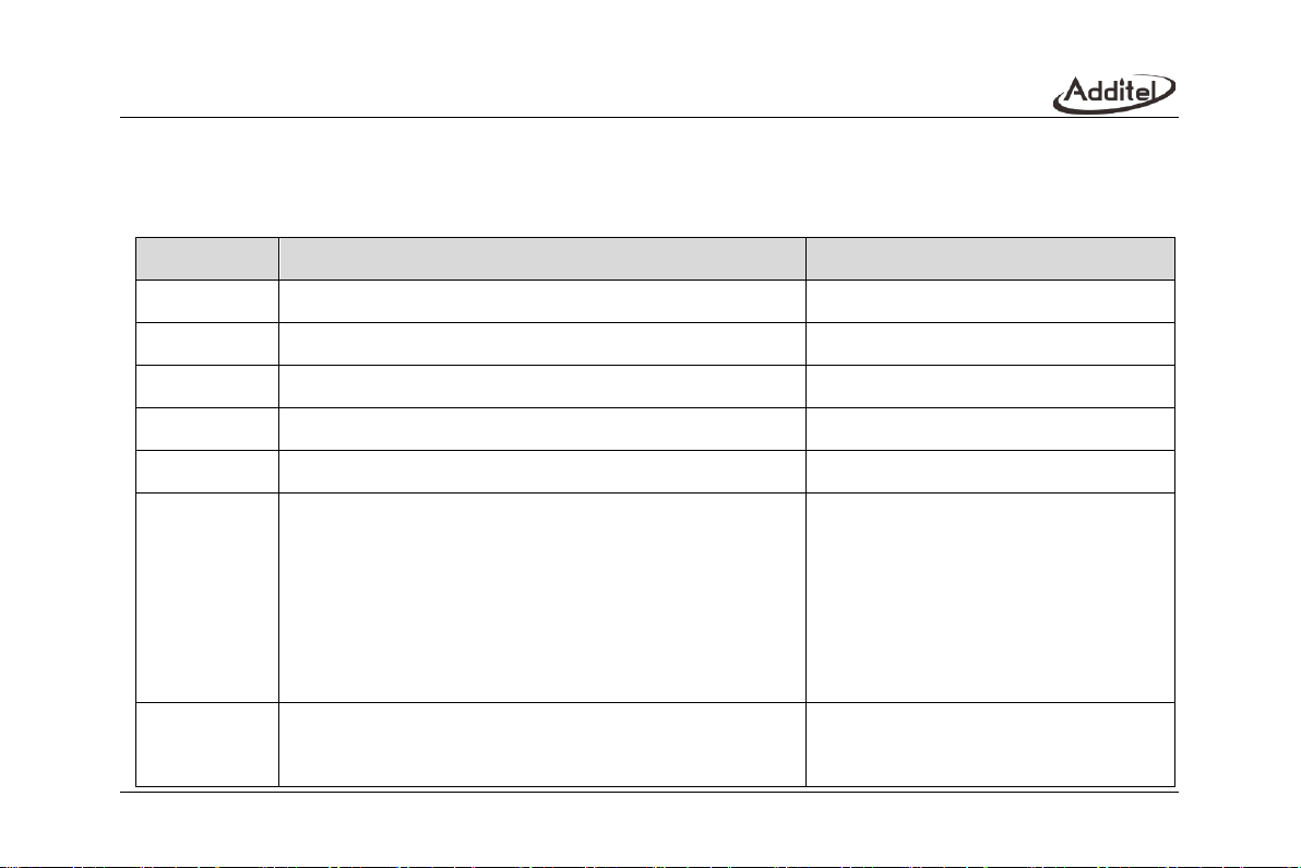
Page 62
52
Date format
Y-M-D / M-D-Y / D-M-Y
Date format setting
Separator
-,/,.
Date separator setting
Time zone
UTC±00:00~12:00
Set device time zone
24 hours
enable
24-hour or 12-hour format
4.5 Product information
Product information is read-only information, includes basic information and the module information.
◆
Basic information: including model, serial number, and system version information.
◆Module information: including Bluetooth, electrical board version, electrical output board version, temperature board
version, ACM board version.
◆
External module information: including external module A and external module B.
5. Data management
◆
Classified management by functional modules, the data saved by each function is kept under the corresponding item,
which is convenient for users;
◆
The functional modules that can save data files include: snapshot, pressure leak test, etc.
◆
Users can delete the data in batches.
Page 63
53
6. Task
The calibrator provides a powerful task function, which can realize fully automatic calibration. At the same time, the
calibration data can be automatically collected, stored, and analyzed, and it can be easily executed and viewed. Click the
task icon on the main interface of the device to enter the task interface.
The documenting task provides task types for four types of equipment: pressure, temperature, flow, and loop. There
are multiple detailed classifications under each task type, and a total of 19 types of DUTs are supported. The process of
using the document task function is as follows:
(1) Create task: Click the add task button at the bottom left of the interface, and click the task type you want to create in
the pop-up DUT type selection interface.
(2) According to the task creation interface presented on the interface, input the information needed to create the task
accurately and in detail (for example: task name, DUT range, etc.). After completing the information, click the OK
button to save the task information. The tasks created after the task information is saved and will be added to
the task list in the main interface of the task.
(3) Select the task just created and click the button to run the task. Complete the configuration required for task
operation and execute the task according to the guidance of the task operation interface.
(4) After the task is executed, click the save button and complete the information required for saving the task data in
the pop-up task saving interface. Click the confirm button to save the task data.
6.1 Calibration pressure devices
6.1.1 Dial pressure gauge and digital pressure gauge
1. Connect to DUT
Connect the external pressure module to the Lemo type connection A or B.
Page 64
54
2. Create the task
Create the corresponding DUT tasks as described above and input the necessary information.
Table 21 Pressure gauge task setting
Subject
Valid value
Description
Name
Numbers, letters, symbols
Task name
S/N
Numbers, letters, symbols
Task S/N
Model
Numbers, letters, symbols
Model of DUT
Pressure type
GP/AP/DP
Pressure type of DUT
Input range
Numbers
Input range of DUT
Accuracy
0.06%,0.1%,0.16%,0.25%,0.4%,0.6%,1%,1.6%,2.5%,4%,custom
Accuracy of DUT. If choose custom, the
input number means the accuracy level of
the dial pressure gauge. For example: input
1.5 for gauge level of 1.5, the range is
(0.001~100)
Division value
0.05/ custom
The minimum resolution of DUT
(0.001-100 for custom)
Page 65
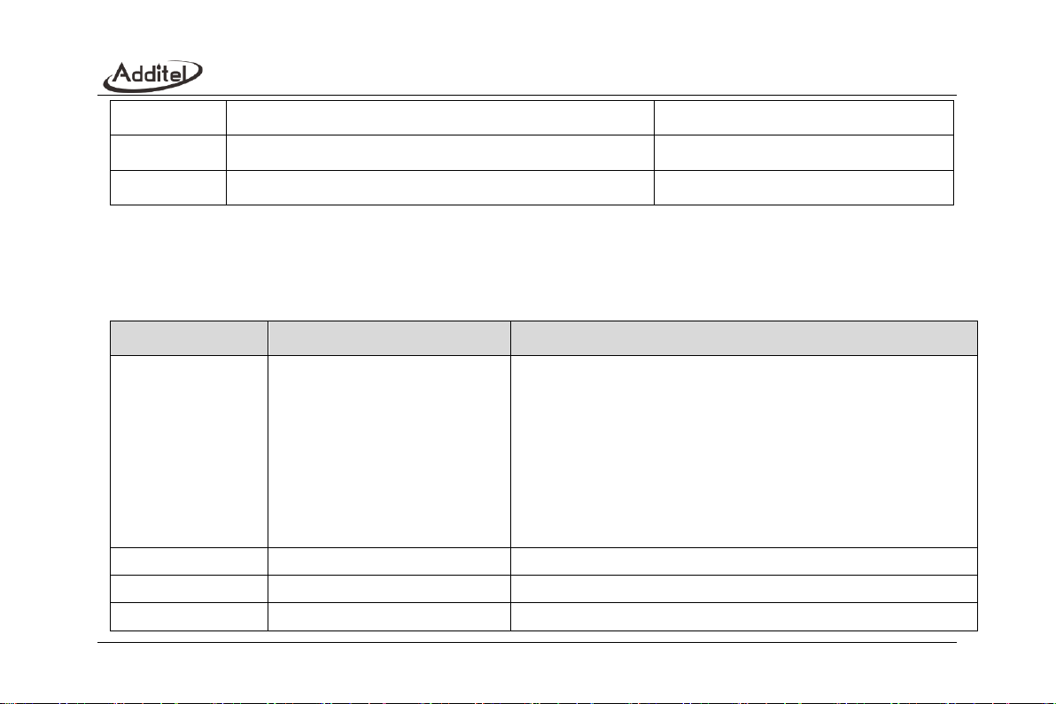
55
Owner
Numbers, letters, symbols
Owner of DUT
Location
Numbers, letters, symbols
Location of DUT
Note
Numbers, letters, symbols
Additional information
3. Task setting
After starting the task, go to the task information interface and set the required information for the task to run. If
multiple pressure modules are connected, you will also need to select which module to use to perform the task.
Table 22 Task running setting
Subject
Valid value
Description
Set point list
The effective value of the set point
pressure depends on the pressure
range of the DUT; up to 17 points
can be set
Set the calibration point for this task, and the calibrator will
automatically set the default calibration points according to the range of
the DUT and the number of set points. However, you can click "Set
Point List" to manually set the calibration points. At this time, the unit of
the set point is consistent with the unit of the DUT. Use the arrow
button on the bottom of the screen or click the number of set points
and then enter the number of set points through the keyboard to
change the number of set points or modify a set point individually.
Cycle count
1,2,3
Cycles during calibration
Strokes
One way/ Round trip
Stroke during calibration
Tapping
On/ off
Tapping on or off
Page 66
56
4. Start the task
◆ Click Start to start the task.
◆ Click button or to switch between lines mode and table mode.
◆ Calibration process:
(1) After the pressure is stable at the set point, read and enter the displayed value of the DUT on the task
interface.
(2) Click the right icon to go to the next point.
(3) Repeat step 1 and 2 until the entire task is finished.
5. Finish the task
After the task is finished, the task report will automatically come up. In the task report page, you can view the detailed
data of each set point. Click the save button at the bottom right of the interface to input the information required and
save the task data of the result.
Table 23 Save task data setting
Subject
Valid value
Description
Operator
Numbers, letters, symbols
Information for operator
Date and time
Valid date and time
Date and time of the task performing
Temperature
Number(℃ as unit)
Ambient temperature when task performing
Humidity
Number(%RH as unit)
Ambient humidity when task performing
Page 67
57
Save as
As found/ As left/ Both
Result type
6.1.2 Pressure transmitter
1. Connect to DUT
◆ Connect the external pressure module to the Lemo type connection A or B.
◆ Connect the DUT output with calibrators electrical module according to DUT output signal type. (current: figure
7/voltage: figure 6/HART: figure 10 or 11)
2. Create the task
Create the corresponding DUT tasks as described above and input the necessary information.
Table 24 Pressure transmitter task setting
Subject
Valid value
Description
Name
Numbers, letters, symbols
Task name
S/N
Numbers, letters, symbols
Task S/N
Model
Numbers, letters, symbols
Model of DUT
Pressure type
GP/AP/DP
Pressure type of DUT
Input
Numbers
Input range of DUT
Page 68
58
Output
Analog signal
:
4~20mA,0~10mA,0~20mA,1~5V,0~5V,0~10V,custom
Output range of DUT
HART device
:
host variable, percentage,
output current, loop current
Accuracy
0.05%,0.1%,0.2%,0.5%,
1%,1.5%,2%,2.5%,custom
Accuracy of DUT. If custom is selected, the input
number establishes the accuracy level of this
pressure transmitter.
Transfer function
Linear / square / square root
Transfer function of the DUT signal
Owner
Numbers, letters, symbols
Owner of DUT
Location
Numbers, letters, symbols
Location of DUT
Note
Numbers, letters, symbols
Additional information
3. Task setting
Refer to the task setting in paragraph 6.1.1.3.
4. Start the task
For part of the content, refer to Start the task in paragraph 6.1.1.4.
The calibrator will automatically use the measured value of the voltage measurement, current measurement, or the
HART measurement according to the DUT output type set by the user, without manually input.
5. Finish the task
Page 69
59
Refer to Finish the task in paragraph 6.1.1.5.
6.1.3 Pressure switch
1. Connect to DUT
Connect the external pressure module to the Lemo type connection A or B. Connect the DUT output with
calibrator’s electrical module. (Figure 6)
2. Create the task
Create the corresponding DUT tasks as described above, and input the necessary information
Table 25 Pressure switch task setting
Subject
Valid value
Description
Name
Numbers, letters, symbols
Task name
S/N
Numbers, letters, symbols
Task S/N
Model
Numbers, letters, symbols
Model of DUT
Pressure type
GP/AP/DP
Pressure type of DUT
Range
Numbers
Input range of DUT
Accuracy
0.5%,1%,1.5%,2%,
2.5%,4%,custom
Accuracy of DUT. If choose custom, the input number means the
accuracy level of this pressure switch.
Set point
Numbers
Action set point of the DUT
Set action type
Open / closed
Action type of the DUT
Page 70
60
Dead band
Numbers
Dead band range of the DUT
Owner
Numbers, letters, symbols
Owner of DUT
Location
Numbers, letters, symbols
Location of DUT
Note
Numbers, letters, symbols
Additional information
3. Task setting
Refer to the task setting in paragraph 6.1.1.3.
4. Start the task
◆ For part of the content, refer to Start the task in paragraph 6.1.1.4
◆ When the pressure switch moves (open/close) during the task, the calibrator will automatically record the
pressure value at the moment of the action, without manually input.
5. Finish the task
Refer to Finish the task in paragraph 6.1.1.5.
6.1.4 I/P Converter
1. Connect to DUT
◆ Connect the external pressure module to the Lemo type connection A or B.
◆ As shown in the Figure 17, connect the DUT output with calibrator’s electrical module.
Page 71
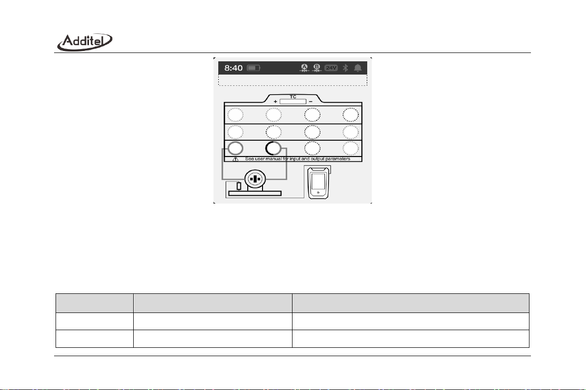
61
Figure 17 I/P converter
2. Create the task
Create the corresponding DUT tasks as described above and input the necessary information.
Table 26 I/P Converter task setting
Subject
Valid value
Description
Name
Numbers, letters, symbols
Task name
S/N
Numbers, letters, symbols
Task S/N
Page 72
62
Model
Numbers, letters, symbols
Model of DUT
Pressure type
GP/AP/DP
Pressure type of DUT
Input
4~20mA,4~12mA,12
~
20mA,custom
Input range of DUT
Output
Numbers
Output range of DUT
Accuracy
0.025%,0.05%,0.1%,0.16%,0.25%,
0.4%,1%,1.6%,2.5%,4%, custom
Accuracy of DUT. If choose custom, the input number means the
accuracy level of this I/P converter.
Transfer function
Linear / square / square root
Transfer function of the DUT
Owner
Numbers, letters, symbols
Owner of DUT
Location
Numbers, letters, symbols
Location of DUT
Note
Numbers, letters, symbols
Additional information
3. Task setting
Refer to the task setting in paragraph 6.1.1.3.
4. Start the task
◆ For part of the content, refer to Start the task in paragraph 6.1.1.4.
◆ During the task performing, the calibrator will output the corresponding current according to the set point list,
and automatically record the DUT output pressure, without manual input.
5. Finish the task
Page 73
63
Refer to Finish the task in paragraph 6.1.1.5.
6.2 Calibrate temperature devices
6.2.1 Temperature indicator
1. Connect to DUT
Connect the DUT input to the TC output (Figure 15) or RTD (Figure 16) output of the calibrator.
2. Create the task
Create the corresponding DUT tasks as described above and input the necessary information.
Table 27 Temperature indicator task setting
Subject
Valid value
Description
Name
Numbers, letters, symbols
Task name
S/N
Numbers, letters, symbols
Task S/N
Model
Numbers, letters, symbols
Model of DUT
Input
Numbers
Input range of DUT, switchable temperature units
Sensor type
TCs or RTDs optional
Sensor type of the DUT
Accuracy
0.06%,0.1%,0.16%,0.25%,0.4%,
0.6%,1%,1.6%,2.5%,4%, custom
Accuracy of DUT
Owner
Numbers, letters, symbols
Owner of DUT
Location
Numbers, letters, symbols
Location of DUT
Note
Numbers, letters, symbols
Additional information
Page 74

64
3. Task setting
Refer to the task setting in paragraph 6.1.1.3.
4. Start the task
◆ For part of the content, refer to Start the task in paragraph 6.1.1.4.
◆ During the task performing, the calibrator simulates and outputs a temperature signal to the DUT, users need to
manually input the value.
5. Finish the task
Refer to Finish the task in paragraph 6.1.1.5.
6.2.2 Temperature transmitter
This type of task is for calibrating temperature transmitter without sensor. It will use the calibrator’s simulate
temperature output as the sensor.
1. Connect to DUT
◆ Connect the DUT with the measurement and output module of the calibrator, as shown in the Figure 18.
Page 75
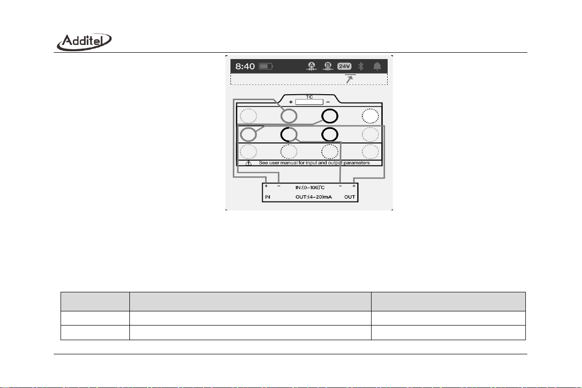
65
2. Create the task
Create the corresponding DUT tasks as described above and input the necessary information. See Table 28.
Table 28 Temperature transmitter task setting
Subject
Valid value
Description
Name
Numbers, letters, symbols
Task name
S/N
Numbers, letters, symbols
Task S/N
Figure 18 Temperature transmitter
Page 76
66
Model
Numbers, letters, symbols
Model of DUT
Input
Numbers
Input range of DUT
Sensor
TCs or RTDs optional
Sensor type of the DUT
Output
Analog signal
:
4~20mA,0~10mA,0~20mA,1~5V,0~5V,0~10V,custom
Output range of DUT
HART devices
:
Process variables, percentage,
Output current, loop current
Accuracy
0.06%,0.1%,0.16%,0.25%,0.4%,
0.6%,1%,1.6%,2.5%,4%, custom
Accuracy of DUT, the input is
customizable
Transfer
function
Linear / square / square root
Transfer function of the DUT signal
Owner
Numbers, letters, symbols
Owner of DUT
Location
Numbers, letters, symbols
Location of DUT
Note
Numbers, letters, symbols
Additional information
3. Task setting
Refer to the task setting in paragraph 6.1.1.1.
4. Start the task
◆ For part of the content, refer to Start the task in paragraph 6.1.1.4.
◆ During the task performing, the calibrator simulates and outputs a temperature signal to the DUT, measures
and records the electrical signal output of the DUT. No manual input required.
Page 77

67
5. Finish the task
Refer to Finish the task in paragraph 6.1.1.5.
6.2.3 Temperature transmitter with sensor
This type of task is for calibrating temperature transmitters with a sensor. During calibration, it requires that you put
the DUT into a temperature source (such as ADT875/878 dry well or thermostatic bath). At the same time, use a
reference sensor to connect to the TC/RTD measurement ports on the calibrator, as shown in Figure 19.
Page 78
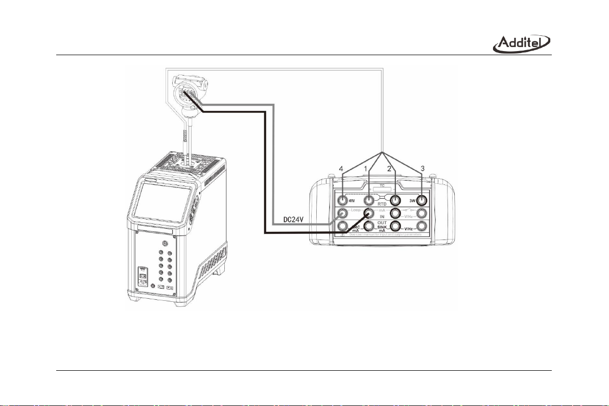
68
1. Connect to
DUT
Figure 19 Temperature transmitter with sensor
Page 79

69
◆ According to the Figure 8 or 9 and the type of reference sensor, to measure the TC or RTD. Then according to
Figure 6 or 7 to measure the voltage or circuit based on the transmitter’s output type.
1. Connect the DUT as shown in figure 19.
2. Create the task
Refer to paragraph 6.2.2.
3. Task setting
Refer to the task setting in paragraph 6.1.1.1.
4. Start the task
◆ For part of the content, refer to Start the task in paragraph 6.1.1.4.
◆ During the task performing, the calibrator simulates and outputs a temperature signal to the DUT, measures
and records the electrical signal output of the DUT. No manual input required.
5. Finish the task
Refer to Finish the task in paragraph 6.1.1.5.
6.2.4 Temperature switch
This type of task is for calibrating temperature switch without sensor. It will use the calibrator’s simulate temperature
output as the sensor.
1. Connect to DUT
◆ Connect the DUT with the measurement and output module of the calibrator, as shown in the Figure 20.
Page 80
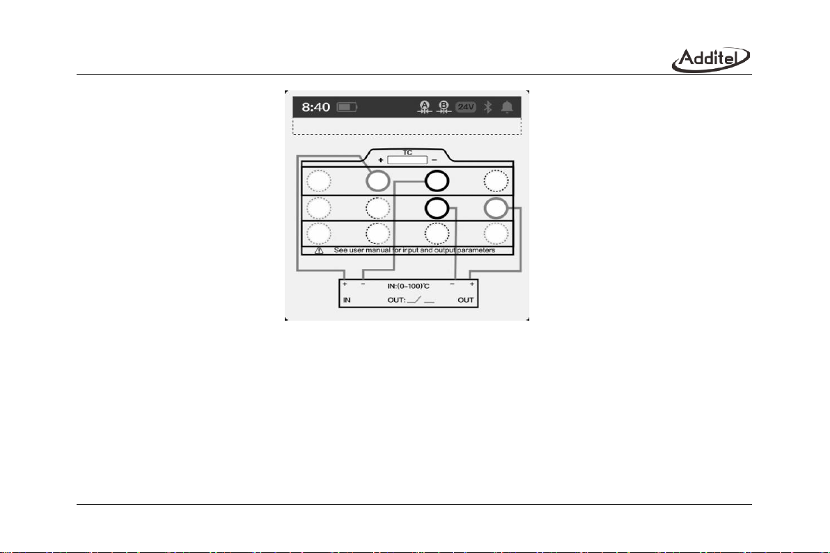
70
Figure 20 Temperature switch
2. Create the task
Create the corresponding DUT tasks as described above and input the necessary information. See Table 29.
Table 29 Temperature switch task setting
Page 81
71
Subject
Valid value
Description
Name
Numbers, letters, symbols
Task name
S/N
Numbers, letters, symbols
Task S/N
Model
Numbers, letters, symbols
Model of DUT
Range
Numbers
Input range of DUT
Sensor
TCs or RTDs optional
DUT sensor type
Accuracy
0.06%,0.1%,0.16%,0.25%,0.4%,
0.6%,1%,1.6%,2.5%,4%,custom
Accuracy of DUT, the input is customizable
Set point
Numbers
Action set point of DUT
Set action type
Opened/ closed
Action type of DUT
Dead band
Numbers
Dead band range of the DUT
Owner
Numbers, letters, symbols
Owner of DUT
Location
Numbers, letters, symbols
Location of DUT
Note
Numbers, letters, symbols
Additional information
3. Task setting
Refer to the task setting in paragraph 6.1.1.3.
4. Start the task
◆ For part of the content, refer to Start the task in paragraph 6.1.1.4.
◆ When the DUT moves (opened/closed) during the task, the calibrator will automatically record the temperature
output at the moment of the action, no manual input required.
Page 82

72
5. Finish the task
Refer to Finish the task in paragraph 6.1.1.5.
6.2.5 Temperature switch with sensor
This type of task is for calibrating temperature switch with sensor. During calibration, it requires to put the DUT into a
temperature source (such as ADT875/878 dry well or thermostatic bath, as shown in Figure 21.
Page 83
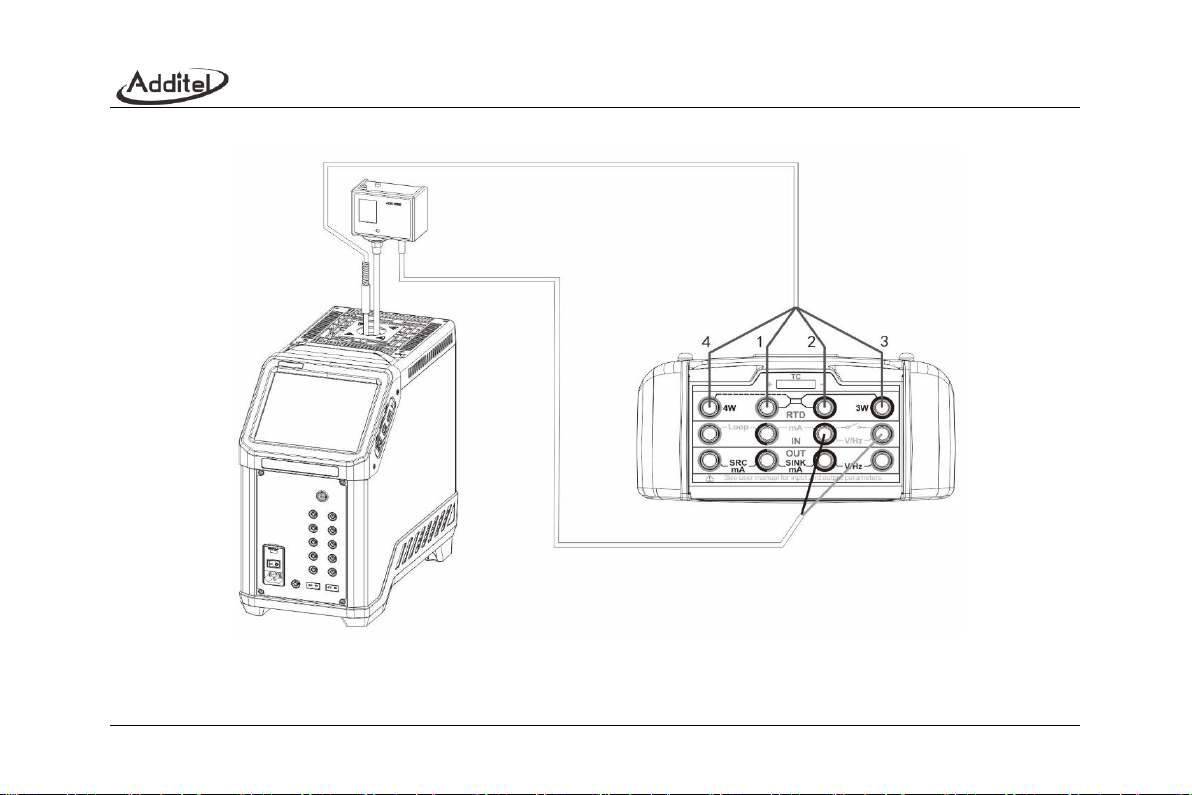
73
Figure 21 Temperature switch with sensor
Page 84

74
1. Connect to DUT
◆ According to the Figure 8 or 9 and the type of reference sensor, to measure the TC or RTD. Then according to
Figure 6 to measure the switch signal.
2. Create the task
Refer to paragraph 6.2.4.
3. Task setting
Refer to the task setting in paragraph 6.1.1.1.
4. Start the task
◆ For this part of the content, refer to Start the task in paragraph 6.1.1.4.
◆ When the DUT moves (open/close) during the task, the calibrator will automatically record the temperature
value at the moment of the action, without manual input.
5. Finish the task
Refer to Finish the task in paragraph 6.1.1.5.
Page 85
75
6.3 Calibrate flow devices
6.3.1 Delta- pressure flowmeter
1. Connect DUT
◆ Connect the external pressure module to the module Lemo type connection A or B.
◆ Connect DUT output with the electrical module of the calibrator according to the signal type of DUT output
(current/ voltage), as shown in the Figure 6 or 7.
2. Create the task
Create the corresponding DUT tasks as described above and input the necessary information. See Table 30.
Table 30 Delta-pressure flowmeter task setting
Subject
Valid value
Description
Name
Numbers, letters, symbols
Task name
S/N
Numbers, letters, symbols
Task S/N
Model
Numbers, letters, symbols
Model of DUT
Input
Numbers
Input range of DUT
Output
Numbers
Output range of DUT, switch the unit to change the input signal
type (current/ voltage)
Accuracy
0.06%,0.1%,0.16%,0.25%,0.4%,
0.6%,1%,1.6%,2.5%,4%,custom
Accuracy of DUT, the output is customizable
Transfer function
Linear / square / square root
Transfer function of the DUT signal
Page 86
76
Owner
Numbers, letters, symbols
Owner of DUT
Location
Numbers, letters, symbols
Location of DUT
Note
Numbers, letters, symbols
Additional information
3. Task setting
Refer to the task setting in paragraph 6.1.1.3.
4. Start the task
◆ For part of the content, refer to Start the task in paragraph 6.1.1.4.
◆ The calibrator will automatically use the measured value of the voltage or current to set the DUT output type,
no manual input required.
5. Finish the task
Refer to Finish the task in paragraph 6.1.1.5.
6.3.2 Instantaneous flowmeter
1. Connect to DUT
◆ According to the type of the DUT, connect the DUT input with the current output (Figure 14), voltage/ frequency
output (Figure 13) of the calibrator’s electrical output module.
2. Create the task
Create the corresponding DUT tasks as described above and input the necessary information. See Table 31.
Page 87
77
Table 31 Instantaneous flowmeter task setting
Subject
Valid value
Description
Name
Numbers, letters, symbols
Task name
S/N
Numbers, letters, symbols
Task S/N
Model
Numbers, letters, symbols
Model of DUT
Input
Numbers
Input range of DUT, switch the unit to change the input signal
type (current/ voltage/ frequency)
Output
Numbers
Output range of DUT, variety of flow units available
Decimals
Option 0~3
The last decimal digit of the DUT’s display
Accuracy
0.06%,0.1%,0.16%,0.25%,0.4%,
0.6%,1%,1.6%,2.5%,4%,custom
Accuracy of DUT, the output is customizable
Transfer function
Linear / square / square root
Transfer function of the DUT signal
Owner
Numbers, letters, symbols
Owner of DUT
Location
Numbers, letters, symbols
Location of DUT
Note
Numbers, letters, symbols
Additional information
3. Task setting
Refer to the task setting in paragraph 6.1.1.3.
4. Start the task
◆ For part of the content, refer to Start the task in paragraph 6.1.1.4.
Page 88
78
◆ The calibrator will automatically switch the output electrical signals to the DUT according to the type of DUT
input set by the user, then the user will need to manually input the value of each set point.
5. Finish the task
Refer to Finish the task in paragraph 6.1.1.5.
6.3.3 Flow volume totalizers
1. Connect to DUT
◆ Connect the DUT input with the frequency output module of the calibrator, as shown in the Figure 14.
2. Create the task
Create the corresponding DUT tasks as described above and input the necessary information. See Table 32.
Table 32 Flow volume totalizers task setting
Subject
Valid value
Description
Name
Numbers, letters, symbols
Task name
S/N
Numbers, letters, symbols
Task S/N
Model
Numbers, letters, symbols
Model of DUT
Frequency
Numbers
Frequency of DUT input signal
Amplitude
Numbers
Amplitude of DUT input signal
Flow unit
Option
Flow unit of DUT, variety of flow units available
Decimals
Option 0~3
The last decimal digit of the DUT’s display
Total flow
Numbers
Expected total flow when the task finish
Page 89
79
K-Param
Numbers
K coefficient of DUT (The flow rate represented by each signal
pulse)
Tolerance
Numbers
Tolerance of DUT
Owner
Numbers, letters, symbols
Owner of DUT
Location
Numbers, letters, symbols
Location of DUT
Note
Numbers, letters, symbols
Additional information
3. Task setting
Refer to the task setting in paragraph 6.1.1.1.
4. Start the task
◆ For part of the content, refer to Start the task in paragraph 6.1.1.4.
◆ The calibrator will automatically generate a continuous pulse output according to user's settings. After all the
pulses are output, users will need to enter the current accumulative flow value of the DUT into the calibrator.
◆ Repeat the above steps until all task cycles finish.
5. Finish the task
Refer to Finish the task in paragraph 6.1.1.5.
6.3.4 Tachometer/ vortex meters
1. Connect to DUT
◆ According to the output signal type of DUT, connect the DUT output with the current measurement (Figure 7) or
voltage/ frequency measurement (Figure 6) of the calibrator.
Page 90
80
2. Create the task
Create the corresponding DUT tasks as described above and input the necessary information. See Table 33.
Table 33 Tachometer task setting
Subject
Valid value
Description
Name
Numbers, letters, symbols
Task name
S/N
Numbers, letters, symbols
Task S/N
Model
Numbers, letters, symbols
Model of DUT
Input
Numbers
Input range of DUT, variety of flow units available
Output
Numbers
Output range of DUT, switch the unit to change the output
signal type (current/ voltage/ frequency)
Decimal digits
Option 0~3
The last decimal digit of the DUT’s display
Accuracy
0.06%,0.1%,0.16%,0.25%,0.4%,
0.6%,1%,1.6%,2.5%,4%,custom
Accuracy of DUT, the output is customizable
Transfer function
Linear / square / square root
Transfer function of the DUT signal
Owner
Numbers, letters, symbols
Owner of DUT
Location
Numbers, letters, symbols
Location of DUT
Note
Numbers, letters, symbols
Additional information
3. Task setting
Refer to the task setting in paragraph 6.1.1.3.
Page 91
81
4. Start the task
◆ For part of the content, refer to Start the task in paragraph 6.1.1.4.
◆ The calibrator will automatically record the measured signal value, the current display of DUT needs to be
entered manually.
5. Finish the task
Refer to Finish the task in paragraph 6.1.1.5.
6.4 Calibrate loop devices
6.4.1 Loop indicators
1. Connect to DUT
◆ Connect the DUT input with the electrical output module of the calibrator, as shown in the Figure 14 (for current
output) or 13 (for voltage output).
2. Create the task
Create the corresponding DUT tasks as described above and input the necessary information. See Table 34.
Table 34 Loop readout task setting
Subject
Valid value
Description
Page 92
82
Name
Numbers, letters, symbols
Task name
S/N
Numbers, letters, symbols
Task S/N
Model
Numbers, letters, symbols
Model of DUT
Range
(4~20)mA,(0~10)mA,(0~20)mA,(1~5)V,(0~5)V,(0~10)V, custom
Input range of DUT
Accuracy
0.025%,0.05%,0.1%,0.16%,0.25%,0.4%,1%,1.6%,2.5%,4%,custom
Accuracy of DUT
Owner
Numbers, letters, symbols
Owner of DUT
Location
Numbers, letters, symbols
Location of DUT
Note
Numbers, letters, symbols
Additional information
3. Task setting
Refer to the task setting in paragraph 6.1.1.1.
4. Start the task
◆ For part of the content, refer to Start the task in paragraph 6.1.1.4.
◆ During the task performing, the calibrator will output the corresponding electrical signal according to the set
point and the DUT input type (current/voltage) set by the user. For the measured value at each set point, users
need to manually input them.
5. Finish the task
Refer to Finish the task in paragraph 6.1.1.5.
Page 93
83
6.4.2 Loop signal source
1. Connect to DUT
◆ Connect the DUT with the measurement module of the calibrator, as shown in the figure 7 (for current
measurement) or 6 (for voltage measurement).
2. Create the task
Create the corresponding DUT tasks as described above and input the necessary information. See Table 35.
Table 35 Loop signal source task setting
Subject
Valid value
Description
Name
Numbers, letters, symbols
Task name
S/N
Numbers, letters, symbols
Task S/N
Model
Numbers, letters, symbols
Model of DUT
Range
(4~20)mA,(0~10)mA,(0~20)mA,(1~5)V,(0~5)V,(0~10)V, custom
Output range of DUT
Accuracy
0.025%,0.05%,0.1%,0.16%,0.25%,0.4%,1%,1.6%,2.5%,4%,custom
Accuracy of DUT
Transfer
function
Linear / square / square root
Transfer function of the DUT
Owner
Numbers, letters, symbols
Owner of DUT
Location
Numbers, letters, symbols
Location of DUT
Note
Numbers, letters, symbols
Additional information
Page 94

84
3. Task setting
Refer to the task setting in paragraph 6.1.1.
4. Start the task
◆ For part of the content, refer to Start the task in paragraph 6.1.1.4.
◆ During the task performing, the calibrator will output electrical signals according to the set point and measure
the DUT output signal, no manual input required during the process.
5. Finish the task
Refer to Finish the task in paragraph 6.1.1.5.
6.4.3 Signal isolator/ converters
1. Connect to DUT
◆ Connect the DUT input with the output module of the calibrator, as shown in the figure 14 (for current output) or
13 (for voltage output). Connect the DUT output with the electrical measurement module of the calibrator
according to the DUT signal type, as shown in figure 7(Current Measurement) and figure 6(Voltage
Measurement).
2. Create the task
Create the corresponding DUT tasks as described above and the necessary information. See Table 26
Table 36 Signal isolator task setting
Page 95
85
Subject
Valid value
Description
Name
Numbers, letters, symbols
Task name
S/N
Numbers, letters, symbols
Task S/N
Model
Numbers, letters, symbols
Model of DUT
Input
(4~20)mA,(0~10)mA,(0~20)mA,(1~5)V,(0~5)V,(0~10)V, custom
Input range of DUT
Output
(4~20)mA,(0~10)mA,(0~20)mA,(1~5)V,(0~5)V,(0~10)V, custom
Output range of DUT
Accuracy
0.05%,0.1%,0.2%,0.5%,1%,1.5%,2%,2.5%,custom
Accuracy of DUT
Transfer
function
Linear / square / square root
Transfer function of the DUT
Owner
Numbers, letters, symbols
Owner of DUT
Location
Numbers, letters, symbols
Location of DUT
Note
Numbers, letters, symbols
Additional information
3. Task setting
Refer to the task setting in paragraph 6.1.1.4.
4. Start the task
◆ For part of the content, refer to Start the task in paragraph 6.1.1.4.
◆ While the task is performing, users need to manually control the electrical signal corresponding to the DUT
output according to the set point and input the reading of the DUT electrical signal into the calibrator, the
Page 96
86
calibrator will give the task result according to the measured value and entered reading as well as the accuracy
analysis set by users.
5. Finish the task
Refer to Finish the task in paragraph 6.1.1.5.
6.4.4 Limit Switches
1. Connect to DUT
◆ Connect the DUT input with the output module of the calibrator, as shown in the figure 14 (for current output) or
13 (for voltage output).
◆ Connect the DUT output with the electrical module of the calibrator, as shown in Figure 6.
2. Create the task
Create the corresponding DUT tasks as described above and input the necessary information.
Table 37 Limit switches task setting
Subject
Valid value
Description
Name
Numbers, letters, symbols
Task name
S/N
Numbers, letters, symbols
Task S/N
Model
Numbers, letters, symbols
Model of DUT
Range
(4~20)mA,(0~10)mA,(0~20)mA,(1~5)V,(0~5)V,(0~10)V, custom
Input range of DUT
Accuracy
0.5%,1%,1.5%,2%,2.5%,custom
Accuracy of DUT
Set point
Numbers
Action set point of DUT
Page 97
87
Set action type
Open/ closed
Action type of DUT
Dead band
Numbers
Switch difference range of the DUT(dead
band)
Owner
Numbers, letters, symbols
Owner of DUT
Location
Numbers, letters, symbols
Location of DUT
Note
Numbers, letters, symbols
Additional information
3. Task setting
Refer to the task setting in paragraph 6.1.1.3.
4. Start the task
◆ For part of the content, refer to Start the task in paragraph 6.1.1.4.
◆ When the DUT acts (open/close) during the task performing, the calibrator will automatically record the
electrical signal value at the moment of the action, no manual input required.
5. Finish the task
Refer to Finish the task in paragraph 6.1.1.5.
7. Applications
7.1 Pressure Unit Converter
Click on the right top of the main interface, select Application, and enter the pressure unit converter.
It supports switching between different units.
Page 98
88
7.2 Leak Test
In the Leak test function, connect the pressure gauge and the calibrator in a gas circuit, then perform leak test to
check for the leakage. Click the blank area in the leak test page to enter the settings, see Table 38.
Table 38 Leak test setting
Subject
Valid value
Description
Pressure type
Gauge/ absolute
Pressure type of DUT, see the calibrator model
Unit
Pressure unit
Pressure unit of DUT
Wait time
Numbers
Set the waiting time before testing
Test time
Numbers
Set the time for leak test
Rate unit
Second/ minute
Unit displayed
7.2.1 Leak Test Performing
1. Connect to gas circuit
a. Connect the device to the gas circuit;
b. Click the start icon at the bottom of the screen, apply pressure to the leak test point;
c. Start counting down the waiting time, and record the real-time pressure at the end of the waiting time as the initial
pressure;
d. Start the test, count down the test time, and start to calculate the real-time leakage, real-time leakage = initial
pressure-real-time pressure;
Page 99
89
e. Record the pressure at the end of the test time as the end pressure;
f. The entire leak detection process ends, and the final leakage = initial pressure - end pressure;
2. The entire process will be displayed in stages in the leak curve at the bottom of the screen.
7.3 PSV test
The PSV test is used for evaluating the opening pressure of the safety valve. In order to ensure the accuracy of the
test, after starting the test, the pressure gauge/calibrator will automatically read the data with a high-speed of 10 times
per second and continuously record the real-time pressure data. It will calculate the maximum pressure and draw the
real-time pressure curve to visually show the trend of the pressure. Click on the start button in bottom area of the PSV
test page to enter the setup, as shown in Table 39.
Table 39 PSV test setting
Subject
Valid value
Description
Pressure type
Gauge/ absolute
Pressure type of DUT, see the calibrator
model
Unit
Different modules support different pressure units
Select corresponding pressure unit
7.3.1 PSV test performing
1. Connect air circuit
a. Connect the device to the air circuit;
Page 100

90
b. Press the Start icon on the right of the screen to start performing, apply the pressure gradually to the safety
valve;
c. Count down the test time and record the real-time pressure value and create the pressure curve, then record the
maximum pressure during the process;
d. Count down complete, the entire leak test process finishes, save the data;
2. The entire process will be shown in the leak test curve at the bottom of the screen
7.4 Thermal calculator
The calibrator provides thermal calculator app, dedicated to variety of industrial TC, RTD and customized type of
sensor. Using the thermal calculator is convenient for converting between temperature and electrical signals of different
sensors.
7.5 Sensor library
In order to meet the needs of custom sensor types, the calibrator provides a sensor library function. In the sensor
library function, users can define new sensor types according to their needs and set relevant parameters in the sensor.
The sensor library supports a total of four types of custom sensors: ITS-90, CVD, RTD and TC.
7.6 Simulate transmitter
The calibrator provides simulate transmitter function, which can easily use the calibrator as a transmitter. Click the
simulate transmitter icon on the main interface to enter the simulate transmitter function. Before using this function,
you should set the transmitter function in the setting menu. Details are shown in Table 40.
Table 40 Simulate transmitter settings
 Loading...