

Page 1
–
1. Disconnect the negative terminal on the battery. With the vehicle on level ground and the
emergency brake set.
2. You will need the following tools:
a. 3/4" Wrench
b. 3/4" Socket
c. 9/16" Wrench
d. 7/36" Allen Wrench
e. 7/16" Wrench
f. 7/16" socket
g. Ratchet
h. Adjustable Wrench
i. 1/2" Drill Bit
j. Dril
k. Teflon Tape
3. Included Items:
a. Aluminum Frame Mount Plates (2)
b. Aluminum Center Mount Plate (1)
c. Cooler Assembly with Dual Fans (1)
d. Painless Performance Fan Relay Wiring Kit - P/N 30102 (1)
e. -10 Port Plug with O-Ring to -8 AN Fitting (2)
f. -8 AN Black Push Lock Fitting (2)
g. -8 AN Black Push Lock high Pressure Hose (15 ft)
h. 3/4" Hose Clamp(4)
i. 3/8" Button Head Allen Bolts(4)
j. 3/8" Nylock nuts(4)
k. 3/8" Washers(8)
l. 1/4" x 1" Hex Head Bolt(6)
m. 1/4" Nylock nuts(6)
n. 1/4" Flat Washers(12)
o. 1/2" Hex Head Bolt(4)
p. 1/2" Hex Nut(4)
q. 1/2" Flat Washer(8)
Page 2
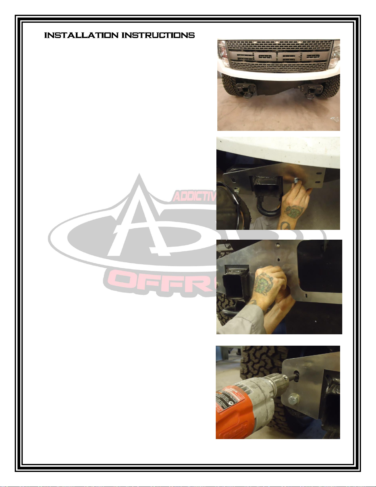
1. Remove front bumper from truck and put aside.
2. Attach the Two(2) aluminum mount plates to the
frame horns, using the 2 holes per side that line up.
Leave the hardware loose at this point.
1. Bolt aluminum cooler mount between the two
outer aluminum mounts using the provided 6 - 3/8"
button head bolts. Tighten these to 20 - 25 ft/lbs.
at this time.
2. Drill the 4 remaining holes, 2 holes on the
aluminum mount plates on each side, to 1/2".
Page 3

3. Next, Bolt the CBR Cooler Unit to the back side of the
center mount plate. Use the supplied 1/4" Hex Head
Bolts, Hex Nuts and Flat Washers.
4. To complete Installation using Factory Bumper, please proceed to Step 7. If you are installing an
A.D.D . Bumper, please skip to Step 8. This is where an assistant or two will come in very
handy.
5. For Stock bumper: Carefully remove the 1/2" Hex Head Bolts and Nuts that are in the position
of the factory bumper studs on the frame horn. Then carefully attach the bumper with the
aluminum frame mount plates between it and the frame horns. Tighten the bumper according
to factory specifications and proceed to the Plumbing and Electrical Instructions.
6. For A.D.D. Bumper: Remove the 1/2" Hex head Bolts and Nuts and hold the bracket to the
frame and carefully line up the Bumper and use the Hardware included with the Bumper to
attach it to the truck. Once all of the hardware is installed, torque to 75 ft. lbs and proceed to
the Plumbing and Electrical Instructions.
Electrical Installation
1. Mount the relay under the hood in a convenient location as close to the fan as possible.
2. Find Temperature Sensor included with the Wiring Kit and place it in the 1 1/2" Pipe Fitting on
the CBR Cooling Assembly. Be sure to use the Teflon tape on the threads to eliminate leaks.
Route the black wire from the relay to the thermostat and cut it to length. Crimp one of
the red female spade terminals onto the wire and attach it to the thermostat. Take the
rolled up black wire and crimp the other red female spade terminal to one end. Attach
this end to the thermostat. Route and attach the other end of the wire to a good
ground. Use one of the supplied ring terminals to make this ground connection.
3. Route and connect the red wire to the Fan “+” Terminal or power wire coming from the
fan motor. Printed “To Electric Fan”.
NOTE: WITH THIS RELAY YOU CAN OPERATE A FAN RATED UP TO 30
AMPS OR TWO FANS AS LONG AS THE TOTAL CURRENT DRAW
FOR BOTH IS LESS THAN 30 AMPS.
Page 4

4. Mount the circuit breaker provided in a convenient location as close as possible to
whichever power source (battery or large terminal on the starter solenoid) you are using
for the fan relay.
5. Route the red wire from the relay to one side of the circuit breaker installed in step 4. Cut
to length and install using a small yellow ring terminal. With another small yellow ring
terminal take the remaining red wire and connect the unused post on the circuit breaker to
the battery source. This wire is printed “To Battery/Constant Hot”
6. Route the gray/white wire to the ignition switch or fan switch; whichever is more
convenient. This wire must see an ignition switched 12 volts in order for the relay to
operate. If you apply battery 12 volts to this wire, the fan will run until the thermostat
senses the engine has cooled off to below 185 degrees Fahrenheit.
Plumbing Installation
1. Lightly oil the O-Rings of the -10 AN Port Plug with O-Ring to -8 AN Fittings and install into the -
10 port on the Cooler unit. Do not over tighten.
2. Attach the -8 AN Push lock fittings to the fitting installed in step 2.
3. Cut the Hose into 2 - 7 1/2' pieces. Push the Hose over the barb of the Push lock fitting and slide
all the way until it is seated flat. Repeat this for the other section of hose.
4. Locate the Factory Cooler Hose that runs between the
small factory transmission cooler and the radiator.
Remove the hose clamps and take out this hose.
5. Safely route the hoses from the cooler unit to the fittings exposed in step 5 on the factory cooler
and the radiator. Cut the hoses to length leaving some play for flex.
IMPORTANT: Before attaching the second hose, carefully fill the cooler unit with the
Recommended Transmission Fluid. This can be achieved by placing a funnel in the unattached
hose and slowly adding until the unit is completely full. Failure to properly full the unit will
may result in insufficient cooling and/or low fluid error.
6. Connect the last hose and secure all of the hose connections using the supplied hose clamps.
7. Clean up and have a cold beverage. That was a good install!
Page 5

For additional support or technical questions,
please call 480.671.0820 or
email info@addictivedesertdesigns.com
 Loading...