

Page 1
Safety information
RECEIVER
B
R
IG
H
T
S
H
A
R
P
100
ADDERLINK
OUT
OUT
TRANSMITTER
ADDERLINK
IN
IN
10
0
• For use in dry, oil free indoor environments only.
• Do not use to link between buildings.
• Not suitable for use in hazardous or explosive
environments or next to highly ammable
materials.
• Ensure that all twisted pair interconnect cables
are installed in compliance with all applicable
wiring regulations.
• Do not connect the CATx link interface (RJ45
style connector) to any other equipment,
particularly network or telecommunications
equipment.
• Where possible, avoid laying the twisted pair
link cable(s) alongside power cables.
• Warning – the power adapter contains live
parts.
• No user serviceable parts are contained within
the power adapter - do not dismantle.
• The primary means to cease operation of the
modules is to remove the power adapter lead.
Ensure that the power adapter is positioned
near to the equipment and is easily accessible.
• Do not use the power adapter if the power
adapter case becomes damaged, cracked or
broken or if you suspect that it is not operating
properly.
• Replace the power adapter with a manufacturer
approved type only.
• If you use a power extension cable with the
modules, make sure the total ampere rating of
the devices plugged into the extension cable
do not exceed the cable’s ampere rating. Also,
make sure that the total ampere rating of all the
devices plugged into the wall outlet does not
exceed the wall outlet’s ampere rating.
• Do not attempt to service the modules yourself.
• The modules and power supplies can get
warm in operation – do not situate them in an
enclosed space without any ventilation.
• The modules do not provide ground isolation
and should not be used for any applications that
require ground isolation or galvanic isolation.
• Use only with grounded outlets at both the
computer and monitor. When using a backup
power supply (UPS), power the computer, the
monitor and the module from the same supply.
• For correct operation, the transmitter
and receiver modules must have ground
connections. At the computer end, this is
achieved by ensuring that the computer that
the module is connected to has a ground
connection. At the audio/visual device end, this
can be achieved by ensuring that the power
supply is connected to a grounded power
outlet. Alternatively, a ground connection will
be made via the monitor, if the monitor is itself
grounded.
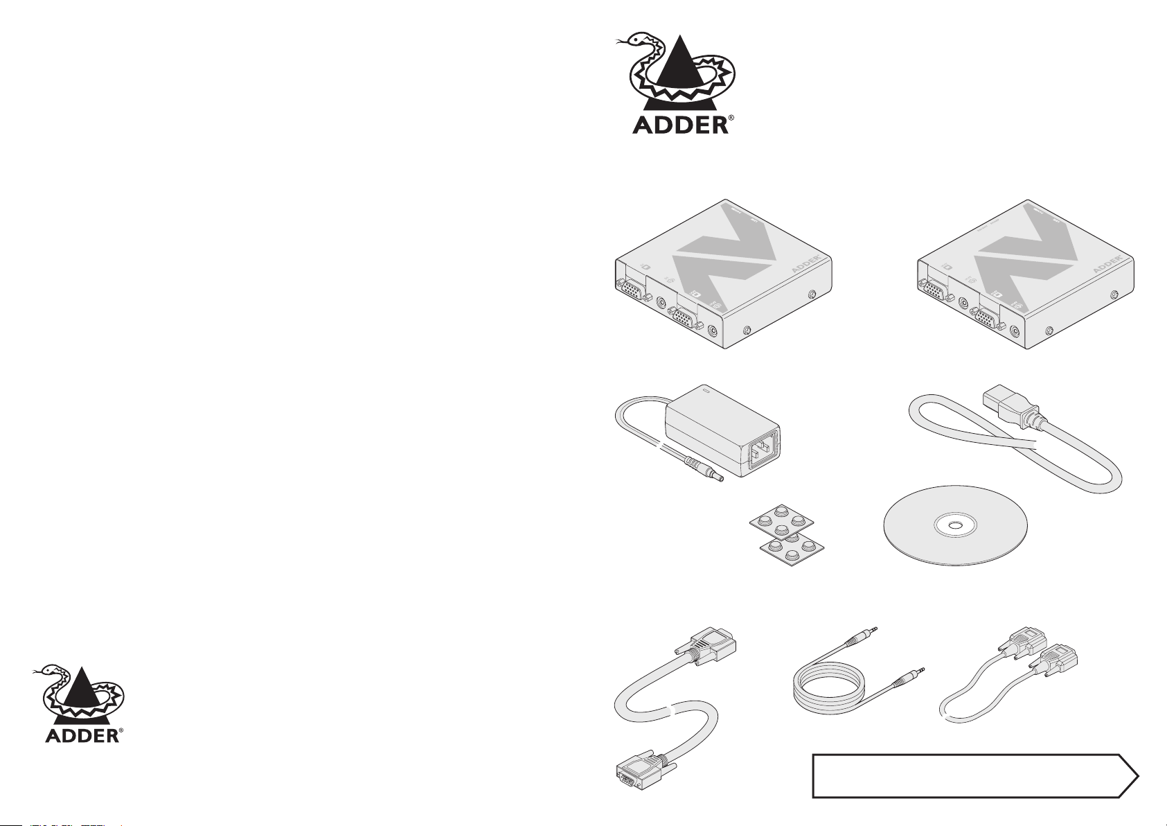
What’s in the box
AdderLink AV
transmitter*
AdderLink AV
Quick Start
* AdderLink
AV100 and
AV200 models are both
packaged as transmitter and
receiver pairs. AV104, AV101, AV100R and
AV100T modules are packaged separately.
For each module:
Power supply adapter
and country-specic
mains cable
AdderLink AV
receiver*
Warranty
Adder Technology Ltd warrants that this product shall be free from defects in workmanship and materials
for a period of two years from the date of original purchase. If the product should fail to operate correctly
in normal use during the warranty period, Adder will replace or repair it free of charge. No liability can
be accepted for damage due to misuse or circumstances outside Adder’s control. Also Adder will not be
responsible for any loss, damage or injury arising directly or indirectly from the use of this product. Adder’s
total liability under the terms of this warranty shall in all circumstances be limited to the replacement value
of this product. If any difculty is experienced in the installation or use of this product that you are unable to
resolve, please contact your supplier.
Adder Technology Limited,
Technology House,
Trafalgar Way, Bar Hill,
Cambridge, CB3 8SQ,
United Kingdom
Tel: +44 (0)1954 780044
Fax: +44 (0)1954 780081
© 2005 Adder Technology Limited • Release 1.0a • October 2005 • Part No. ADD0060
All trademarks are acknowledged. Documentation by Corporate Text & Design (www.ctxd.com)
Adder Corporation,
29 Water Street,
Newburyport,
MA 01950,
United States of America
Tel: +1-888-932-3337
Fax: +1-888-275-1117
Email: support@adder.com
Web: www.adder.com
Self adhesive
rubber feet
What you may additionally need
Video cable
Adder P/N: VSC18
Full user guide available on the CD-ROM and also at www.adder.com
CD-ROM
containing skew
test pattern and
documentation
Stereo audio cable
Adder: P/N VSC22
Serial cable
Adder P/N: CAB-9M/9F-2M
Connection overview inside
Page 2
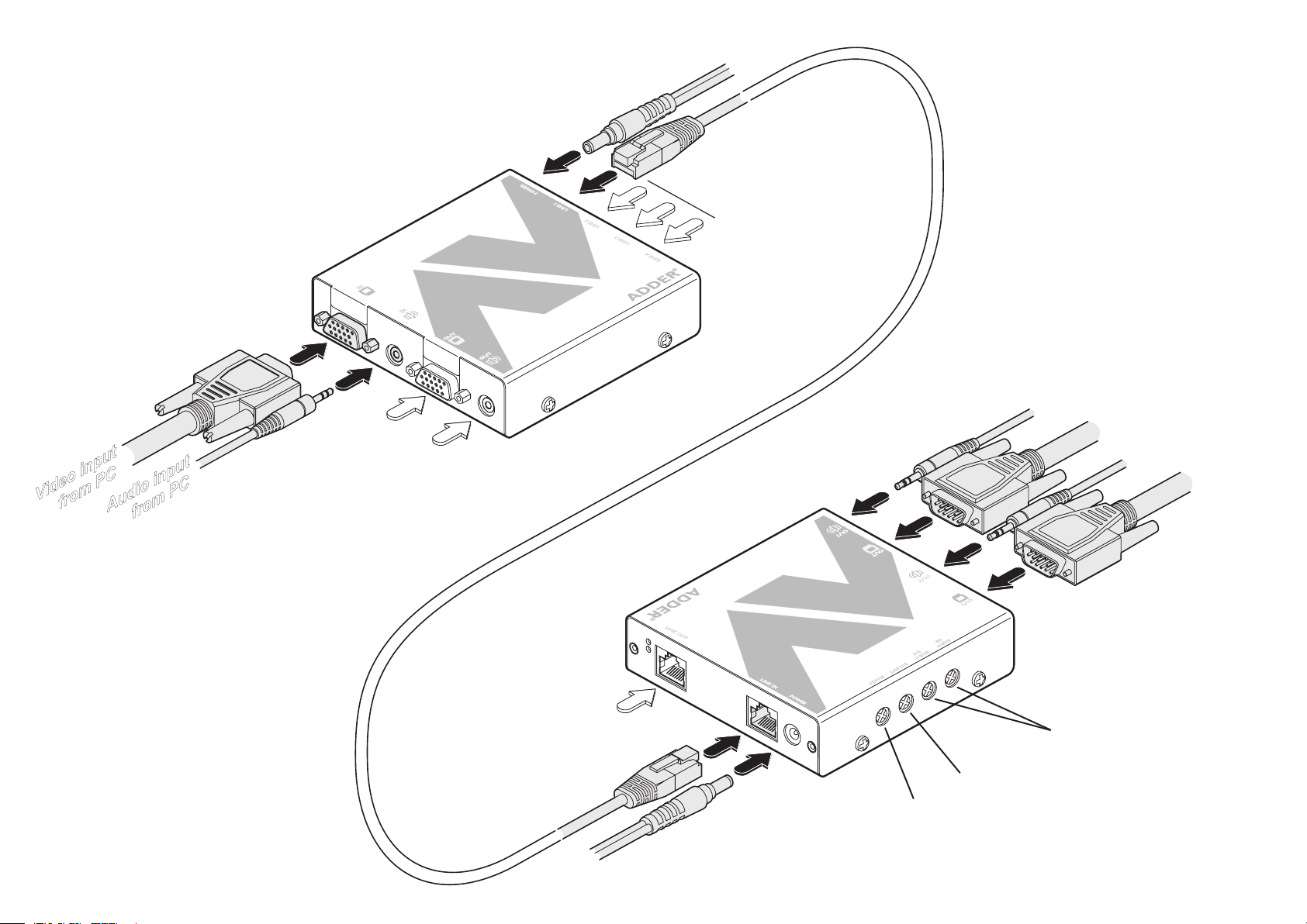
Video
input
from
PC
Optional
output
to
local
video
monitor
Power
input
CATx
link
connections
to
receivers
2, 3
and
4
(AV104
models
only)
Audio
input
from
PC
Optional
output
to
local
speakers
CATx
link
up
to
300m
(
1000
feet)
Audio
output
to
speakers
Audio
output
to
speakers
Video
output
to
display
V
ideo
output
to
display
Power
input
Optional
link
output
to
a
cascaded
receiver
(AV101
models
only)
TRANSMITTER
LINK
2
LINK
3
LINK
4
10
4
ADDERLINK
IN
IN
RECEIVER
SKEW
GB
SKEW
RG
BRIGHT
SHARP
L
INKOU
T
101
ADDERLINK
OUT
OUT
Connection overview
• For full explanations of connections, including cascade
connections, please refer to the full user guide provided
on the CD-ROM and also at www.adder.com.
• Please consult the Safety information on the rear page
of this quick start guide.
Locations
Please consider the following important points
when planning the positions of your AdderLink AV
modules:
• Take care not to exceed the maximum link
cable lengths (please refer to the section
‘Making cascade connections’ in the main user
guide for a full explanation).
• Ensure that the transmitters are as close as
possible to the source PC system and the
receivers are similarly close to the display
modules. Use video connection cables that are
correctly shielded and are no longer than 6m
in length.
• Wherever possible, choose routes for the
CATx twisted pair link cables that avoid mains
power cables.
• Remember a mains power socket is required
for each transmitter and receiver.
Resolutions and cable lengths
The maximum resolutions achievable are:
1600 x 1200 x 60Hz at 200m and 1280
x 1024 x 60Hz at 300m. If you are using
lower resolutions then it may be possible
to achieve longer transmission distances
although we do not recommend runs
longer than 300m in any installation. If
you are running shorter cables then it may
be possible to use more cascades.
Sharpness adjustment dial
Adjustments for skew compensation
between colours (AV101 and AV200
models only)
Brightness adjustment dial
 Loading...