


AdderView DDX
Experts in
Connectivity
Solutions
Switching
Solutions
User Guide

Contents
Introduction
Welcome ................................................................................................................ 2
Cable type and distance rules ................................................................ 2
Access permissions ........................................................................................ 3
Port designations ............................................................................................ 3
Supplied items ....................................................................................................... 4
Optional extras .....................................................................................................6
Installation
Locations ................................................................................................................ 7
Connections .......................................................................................................... 8
Computer connections: Video ..................................................................... 8
Computer connections: USB .......................................................................8
Computer connections: Data link ..............................................................8
Switch connections: Computer links .........................................................9
Switch connections: User console links ....................................................9
Switch connections: Network link..............................................................9
Switch connections: Options port .............................................................. 9
Switch connections: Power ........................................................................10
Console connections: Video .......................................................................11
Console connections: USB .........................................................................11
Console connections: Audio ......................................................................12
Console connections: Data link ................................................................12
Console connections: Options port ........................................................12
Console connections: Power .....................................................................13
Conguration
Accessing DDX Matrix .....................................................................................14
Using DDX Matrix .............................................................................................15
The Dashboard page ...................................................................................15
Quick guide to creating a new installation .............................................16
The Control page .........................................................................................17
The Congure pages ...................................................................................18
Congure > Consoles ...........................................................................20
Congure > Consoles > Receivers ....................................................22
Congure > Computers .......................................................................23
Congure > Computers > Transmitters ...........................................25
Reallocating ports ...................................................................................26
The Users page .............................................................................................27
The Maintenance pages ...............................................................................28
Maintenance > Diagnostics ..................................................................28
Maintenance > System Operations ....................................................29
Maintenance > Settings .........................................................................30
Resetting and recovering .................................................................................31
Operation
Viewing the OSD................................................................................................32
Using Audio .........................................................................................................33
Indicators .............................................................................................................34
Further information
Getting assistance ..............................................................................................36
Appendix 1 - Link cable interference protection ........................................37
Appendix 2 - Firmware upgrades ...................................................................38
Warranty and Safety information ...................................................................39
Radio frequency energy ....................................................................................40
INSTALLATION
CONFIGURATIONOPERATION
FURTHER
INFORMATION
INDEX
Index
1
Introduction
WELCOME
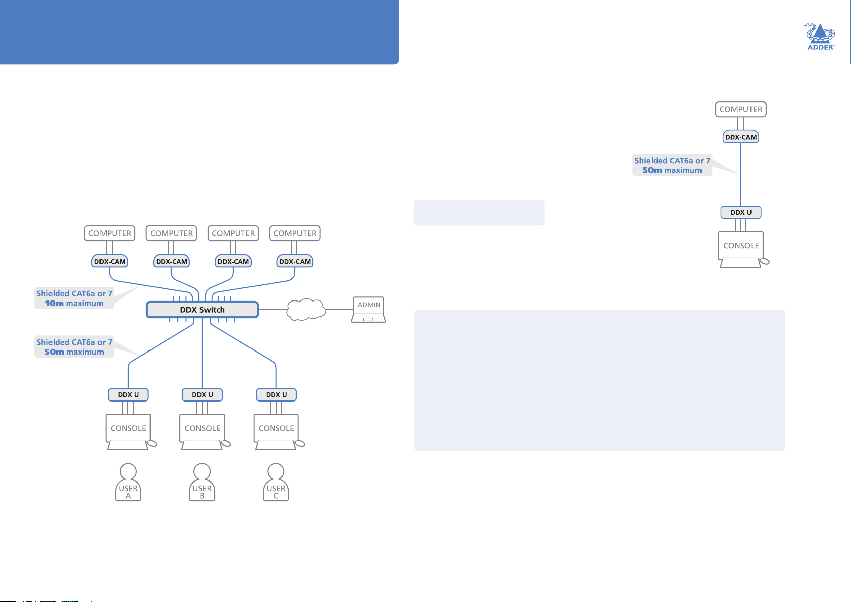
Thank you for choosing the AdderView DDX system. This adaptive system makes
sharing numerous host computers among multiple users straightforward and exible.
Every computer is linked, via its USB and video ports, to a compact DDX-CAM
module while each set of peripherals are connected to a DDX-USR module (to form
Consoles).
The various computers and consoles are then linked, via CAT6a or CAT7 cable
with S/FTP, S/STP or PiMF shielding (see Appendix 1 for details), to a central
DDX switch. Each user can then, subject to the privileges granted by the admin, gain
quick access to any of the required computers.
If required, computers and consoles can be individually connected
in order to take advantage of the DDX extender properties
without the switching.
Note: Do not use unshielded
cables with the DDX modules.
Cable type and distance rules
• Cable screening/shielding is required. The best cable shielding specications for use
with the DDX system are: S/FTP, S/STP or PiMF.
• Extension distances up to 50m are supported with single uninterrupted runs of
recommended cable (shielded CAT6a or CAT7 cable).
• CAT5 or CAT5e cables must not be used with this product.
• Overall cable runs must be reduced by 5m for each additional cable coupling.
• All patch cables should be as short as possible and should be no longer than 2m.
• It is recommended that Adder shielded CAT7 cables are used for maximum
performance.
INSTALLATION
CONFIGURATIONOPERATION
FURTHER
INFORMATION
An integral part of DDX switches is the DDX Matrix, a browser-based conguration
and management tool that allows one or more remote admin user(s) to monitor
and maintain all aspects of operation.
INDEX
2
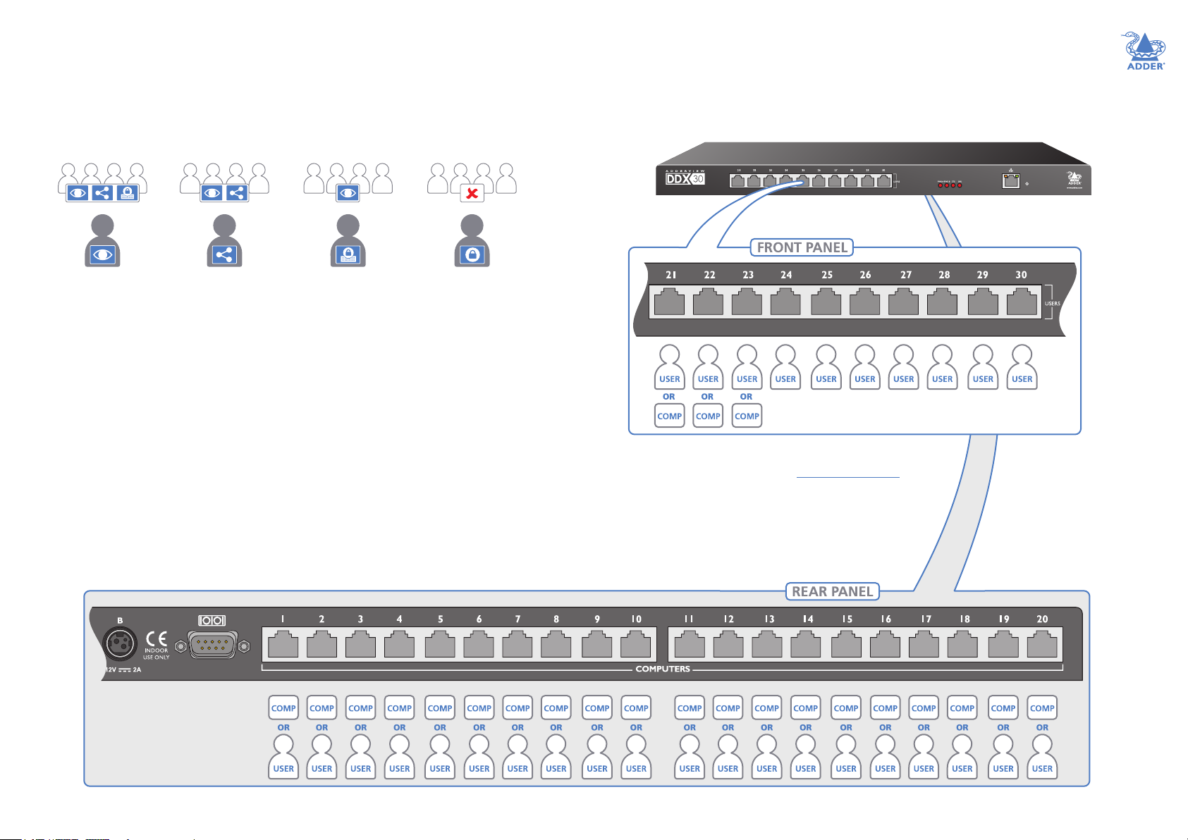
Access permissions
The DDX switch uses a system of hierarchal Access permissions to mediate
between numerous consoles and multiple computers. Each console is granted the
use of up to four types of access permissions to each computer, most of which
inuence how other users can gain simultaneous access to the same computer. The
four access permissions, and their effects on other console users are as follows:
Port designations
By default the DDX switch provides 10 user console ports on its front panel and
20 computer ports along its rear panel, however, these designations are not xed.
If your installation requires a greater number of computers or has a need for
more user consoles, you can alter the allocation of these standard ports to suit:
INSTALLATION
VIEW ONLY
The console user
can view the chosen
computer’s output but
cannot control it.
Once selected,
other consoles can
simultaneously use
VIEW ONLY,
SHARED ACCESS or
EXCLUSIVE
for the same computer.
Note: The hierarchy of permissions shown here increases from left to right.
SHARED ACCESS
The console user can
view and control the
chosen computer’s
output.
Once selected,
other consoles can
simultaneously use
VIEW ONLY or
SHARED ACCESS
for the same computer.
EXCLUSIVE
The console user can
view and control the
chosen computer’s
output.
Once selected,
other consoles can
simultaneously use
VIEW ONLY
for the same computer.
PRIVATE
The console user can
view and control the
chosen computer’s
output.
Once selected, all
other consoles are
completely locked
out from the same
computer.
CONFIGURATIONOPERATION
Ports 21 to 23 can be reallocated as computer ports.
For more details, please see Reallocating ports.
FURTHER
INFORMATION
Any of the 20 rear
panel computer ports
can be reallocated as
user console ports
INDEX
3
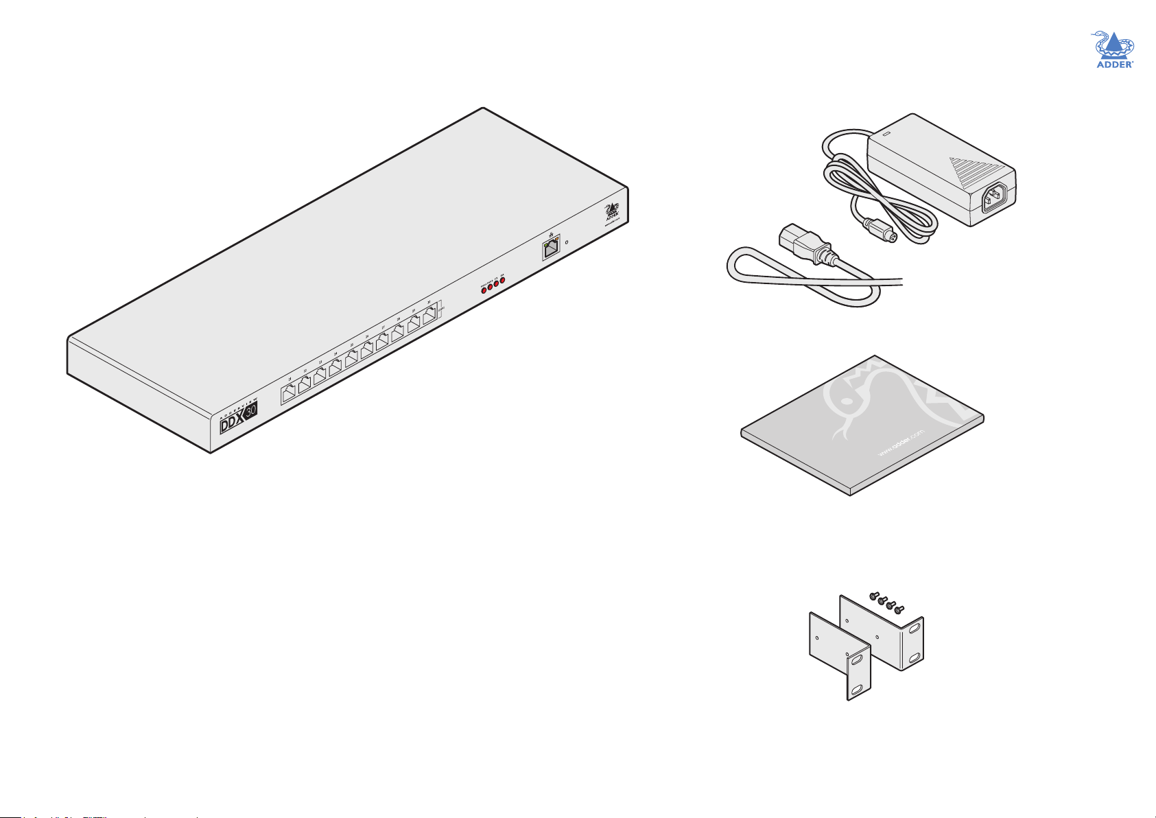
SUPPLIED ITEMS
DDX switch package
AdderView DDX
switch
Power adapter with locking
connector and country-
specic power cord
INSTALLATION
CONFIGURATIONOPERATION
Information wallet
containing:
Four self-adhesive rubber feet
Safety document
19” rack mount
brackets and four
screws
FURTHER
INFORMATION
INDEX
4

DDX-USR package
DDX-USR module
DDX-CAM DisplayPort option
DDX-CAM module with USB
and DisplayPort connections
Part number: DDX-CAM-DP
INSTALLATION
Power adapter with locking
connector and country-
specic power cord
Information wallet
containing:
Four self-adhesive rubber feet
Safety document
DDX-CAM DVI option
DDX-CAM module with USB
and DVI-D connections
Part number: DDX-CAM-DVI
CONFIGURATIONOPERATION
FURTHER
INFORMATION
INDEX
5
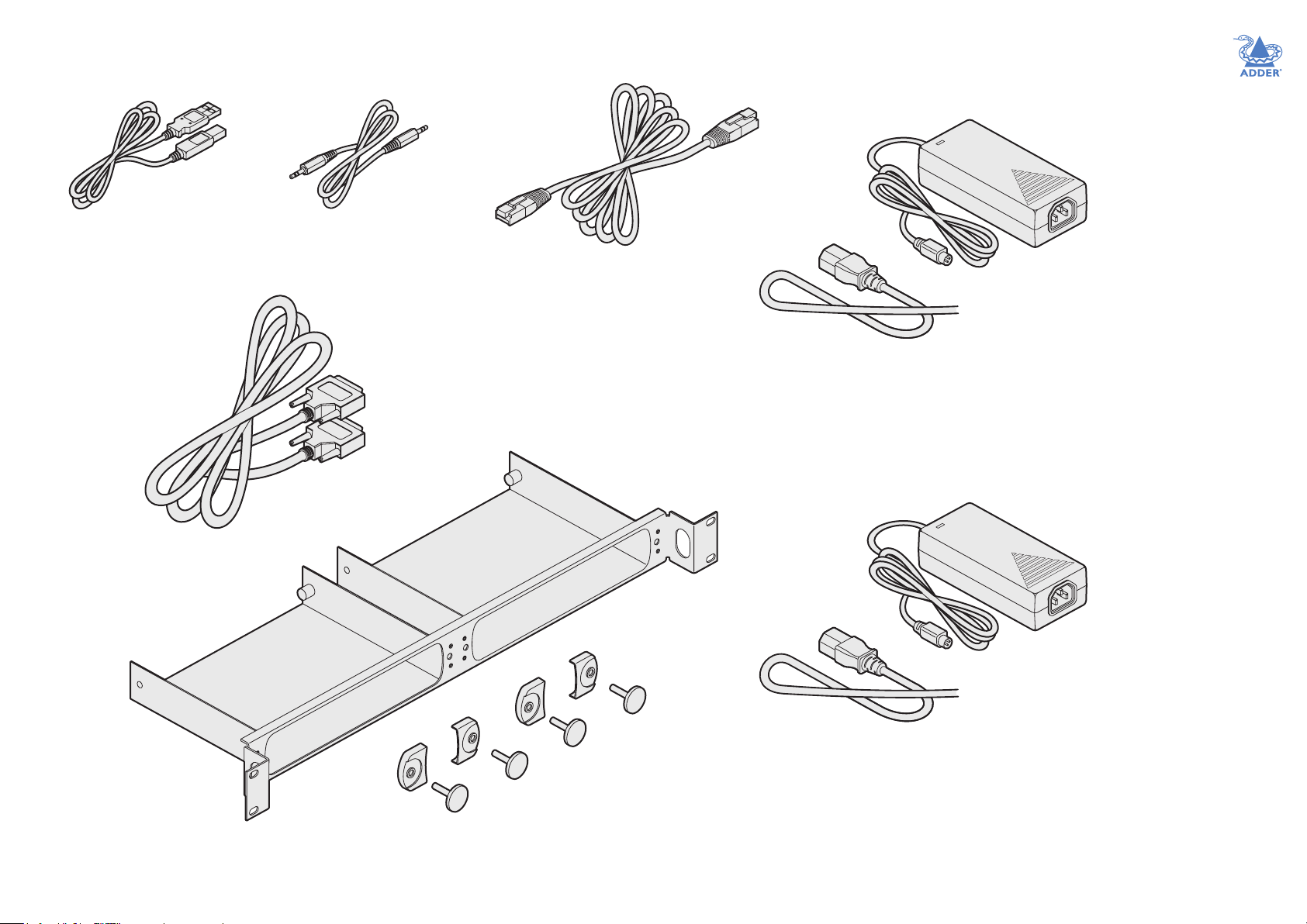
OPTIONAL EXTRAS
USB cable 2m (type A to B)
Part number: VSC24
DVI-D 2m cable
Part number: VSCD1
Audio cable 3m (3.5mm stereo jacks)
Part number: VSC22
CAT7 shielded cable
3m
Part number: VSCAT7-3M
10m
Part number: VSCAT7-10M
30m
Part number: VSCAT7-30M
50m
Part number: VSCAT7-50M
Dual DDX-USR rack mount bracket
plus four retaining clamps and bolts
Part number: RMK8
Replacement power adapter with locking
connector for DDX-USR module
Part number: PSU-IEC-12VDC-1.5A
Country-specic power cords
CAB-IEC-AUS (Australia)
CAB-IEC-EURO (Central Europe)
CAB-IEC-UK (United Kingdom)
CAB-IEC-USA (United States)
CAB-IEC-JAPAN (Japan)
Additional or replacement power adapter
with locking connector for DDX switch
Part number: PSU-IEC-12VDC-5A
Country-specic power cords
CAB-IEC-AUS (Australia)
CAB-IEC-EURO (Central Europe)
CAB-IEC-UK (United Kingdom)
CAB-IEC-USA (United States)
CAB-IEC-JAPAN (Japan)
INSTALLATION
CONFIGURATIONOPERATION
FURTHER
INFORMATION
INDEX
6

Installation
LOCATIONS
Please consider the following important points when planning the position of the
AdderView DDX modules:
• If used, position the DDX switch in a central position that serves the host computer
systems and user modules without exceeding the maximum link lengths. It will also
require a source of mains power.
• Situate each DDX-USR module close to the peripherals to which it will be connected
and near to a source of mains power.
• Consult the precautions listed within the Safety information section.
INSTALLATIONCONFIGURATIONOPERATION
FURTHER
INDEX
7
INFORMATION

CONNECTIONS
Connections do not need to be carried out in the order given within this guide, however,
where possible connect the power in as a nal step. Connections are split into the
following three areas:
• Computer connections - a DDX-CAM module links to each host computer.
• Switch connections - when used, a DDX switch unit sits at the heart of the system.
• Console connections - the peripherals (keyboard, display, etc.) connect to DDX-USR modules.
Computer connections: Video
Two types of DDX-CAM modules are available:
• DVI-D and USB,
or
• DisplayPort and USB.
If a computer has more than one video output, use additional DDX-CAM modules to
separately link the additional video stream(s) with other ports on the DDX switch.
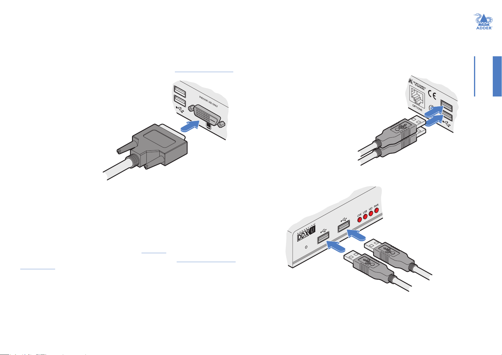
To connect the video port
1 Connect the video lead of the DDX-CAM
to the DVI-D or DisplayPort video port of
the host computer.
DVD-D video
port on the
host computer
Computer connections: USB
Each DDX-CAM module requires a single USB connection to the computer. This
provides essential power for the DDX-CAM module in addition to the USB signals. Each
DDX-USR module acts as a USB 2.0 hub and thus provides four sockets for peripherals.
To connect the USB port
1 Connect the USB cable of the DDX-CAM module
to a vacant USB socket on your host computer.
INSTALLATIONCONFIGURATIONOPERATION
USB lead from
the DDX-CAM
Computer connections: Data link
Each DDX-CAM module is linked via a shielded (S/FTP or S/STP) CAT6a or CAT7 cable
either to a central DDX switch module or directly to a DDX-USR module (for a single
system installation).
Maximum link cable lengths:
• DDX-CAM to DDX switch - 10 metres (32 feet) maximum.
• DDX-CAM to DDX-USR module - 50 metres (164 feet) maximum.
DVI-D video
lead from the
DDX-CAM
DisplayPort
video lead
from the
DDX-CAM
OR
DisplayPort
on the host
computer
To link the DDX-CAM module
1 Connect the RJ-45 plug of the link cable to the
socket located at the end of the DDX-CAM module.
Shielded CAT6a
or CAT7 link
from DDX switch
or DDX-USR
module
FURTHER
INFORMATION
INDEX
Note: Do not use unshielded
cables with the DDX modules.
8
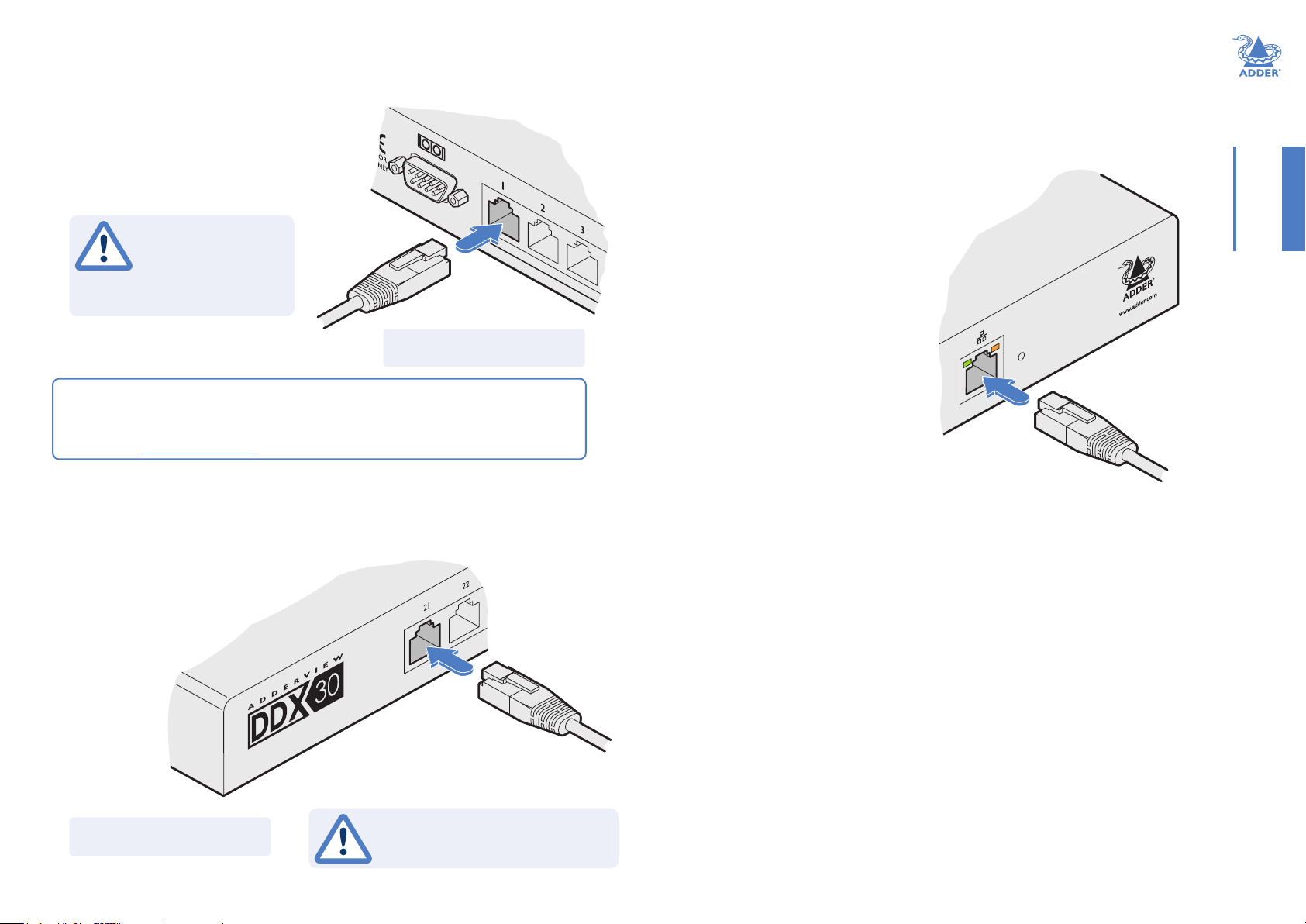
Switch connections: Computer links
The host computer links are made to the sockets on the rear panel of the DDX switch.
To connect a computer link
1 Connect a shielded (S/FTP or S/STP) CAT6a
or CAT7 cable (10m maximum) from the
remote DDX-CAM computer module to a
vacant RJ-45 socket on the rear panel of the
DDX switch.
Switch connections: Network link
All system conguration is carried out via an Ethernet link, allowing adjustments to be
made by authorized admin users located next to the DDX unit, or anywhere. The autosensing network port can determine between 10, 100Mbps or 1Gbps links and can also
adjust to straight or cross-over cables.
To connect a network link
1 Connect the CATx cable from an Ethernet switch or from
a local computer.
These are NOT
Ethernet/network
ports and must NEVER
be connected to any
networking equipment.
Shielded CAT6a or CAT7 link from a
remote DDX-CAM computer module
Note: Do not use unshielded
cables with the DDX modules.
Reallocating ports
By default the DDX switch provides 20 computer ports along its rear panel and 10
user ports along its front panel. If necessary, these standard arrangements can be
changed. See Reallocating ports.
Switch connections: User console links
The user console links are made via the sockets at the front of the DDX switch.
To connect a user console link
1 Connect a shielded (S/FTP or S/STP)
CAT6a or CAT7 cable (50m
maximum) from the remote
DDX-USR module to a
vacant RJ-45 socket
on the front
panel of the
DDX switch.
INSTALLATIONCONFIGURATIONOPERATION
From a network switch
or nearby computer
Switch connections: Options port
The options port is reserved for future use.
FURTHER
INFORMATION
Note: Do not use unshielded
cables with the DDX modules.
Shielded CAT6a or CAT7 link from
a remote DDX-USR module
These are NOT Ethernet/network
ports and must NEVER be connected
to any networking equipment.
INDEX
9
Switch connections: Powe r
Each DDX switch is supplied with a single power adapter but offers the facility to use
a second input in order to provide operational redundancy. The DDX unit can operate
perfectly well from a single power adapter operating alone. When two adapters are
connected, the unit will spread its load between them; should one power input fail, 100%
of the load will be transferred to the other power adapter without a break in operation.
Remote checking of the power inputs is possible at any time via the browser interface -
see Maintenance > Diagnostics for details.
There is no on/off switch on the DDX unit, so operation begins as soon as power is
applied at either port.
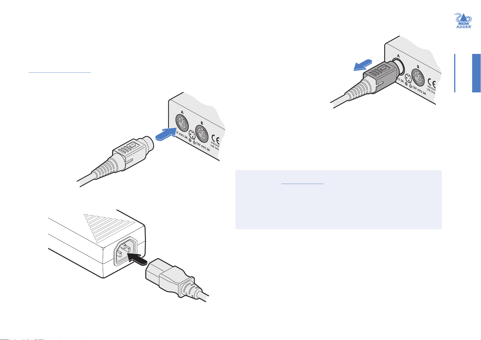
To connect the power adapter
1 Attach the output plug of the supplied power adapter to
either power input socket on the left side of the rear panel.
From the
power adapter
2 Connect the IEC connector of the supplied country-specic power cord to the socket
of the power adapter.
To disconnect the power adapter
1 Isolate the power adapter from the
mains supply.
Note: If you are replacing one of dual
power adapters during operation, it is
not necessary to also remove power
from the other adapter.
2 Grasp the outer body of the power
adapter plug where it connects with
the module.
3 Gently pull the body of the outer
plug away from the module. As the
body of the plug slides back, it will
Gently pull back the plug outer
body to release the lock
release from the socket and you can
fully withdraw the whole plug.
IMPORTANT: Please read and adhere to the electrical safety information
given within the Safety information section of this guide. In particular, do not
use an unearthed power socket or extension cable.
Note: Both the modules and the power supplies generate heat when in operation and will
become warm to the touch. Do not enclose them or place them in locations where air cannot
circulate to cool the equipment. Do not operate the equipment in ambient temperatures
exceeding 40 degrees Centigrade. Do not place the products in contact with equipment whose
surface temperature exceeds 40 degrees Centigrade.
INSTALLATIONCONFIGURATIONOPERATION
3 Connect the power cord to a nearby main supply socket.
4 Where power redundancy is required, repeat steps 1 to 3 for a second power adapter.
FURTHER
INFORMATION
INDEX
10
Console connections: Video
A Single Link DVI-D port is provided on the rear panel of the user module.
The DDX-USR module supports one video display with pixel clocks up to 165MHz
(equivalent to a maximum resolution of 1920 x 1200 at 60Hz - aka ‘WUXGA’).
If a second display is required to support a dual video installation, use another DDX-
USR module to drive the second display, and combine the two user modules into a single
Console within the DDX Matrix conguration application - See Congure > Computers.
To connect the video display
1 Connect the DVI-D video cable from your video
display to the video output port on the rear panel
of the user module.
From your
video display
Console connections: USB
The DDX-USR module contains a USB hub that can support up to four v1.1 or v2.0 USB
devices (in any combination). All four USB sockets, two on the front panel and two on
the rear, are identical in operation.
Note: In multi-head installations, the USB devices must be attached only to the DDX-USR
module that drives the main display.
To connect USB devices
1 Connect your USB keyboard and mouse to any of
the four sockets distributed on the front and rear
panels of the user module.
Rear panel
From USB keyboard
and mouse
INSTALLATIONCONFIGURATIONOPERATION
EDID management
The DDX switch provides a number of xed EDID (Extended Display Identication
Data) proles that will suit a large number of video display congurations. If additional
EDID denitions are required for your installation, you can clone new denitions from
connected video displays and add these to the list of available denitions.
For details about cloning EDIDs from displays, see Add EDID.
For details about applying an EDID to a particular computer, see Congure > Computers
> Transmitters.
DDX-USR module switches
The two switches on the DDX-USR module are reserved for future use and must both
remain in the OFF position.
Front panel
From USB
keyboard and
mouse
FURTHER
INFORMATION
INDEX
11
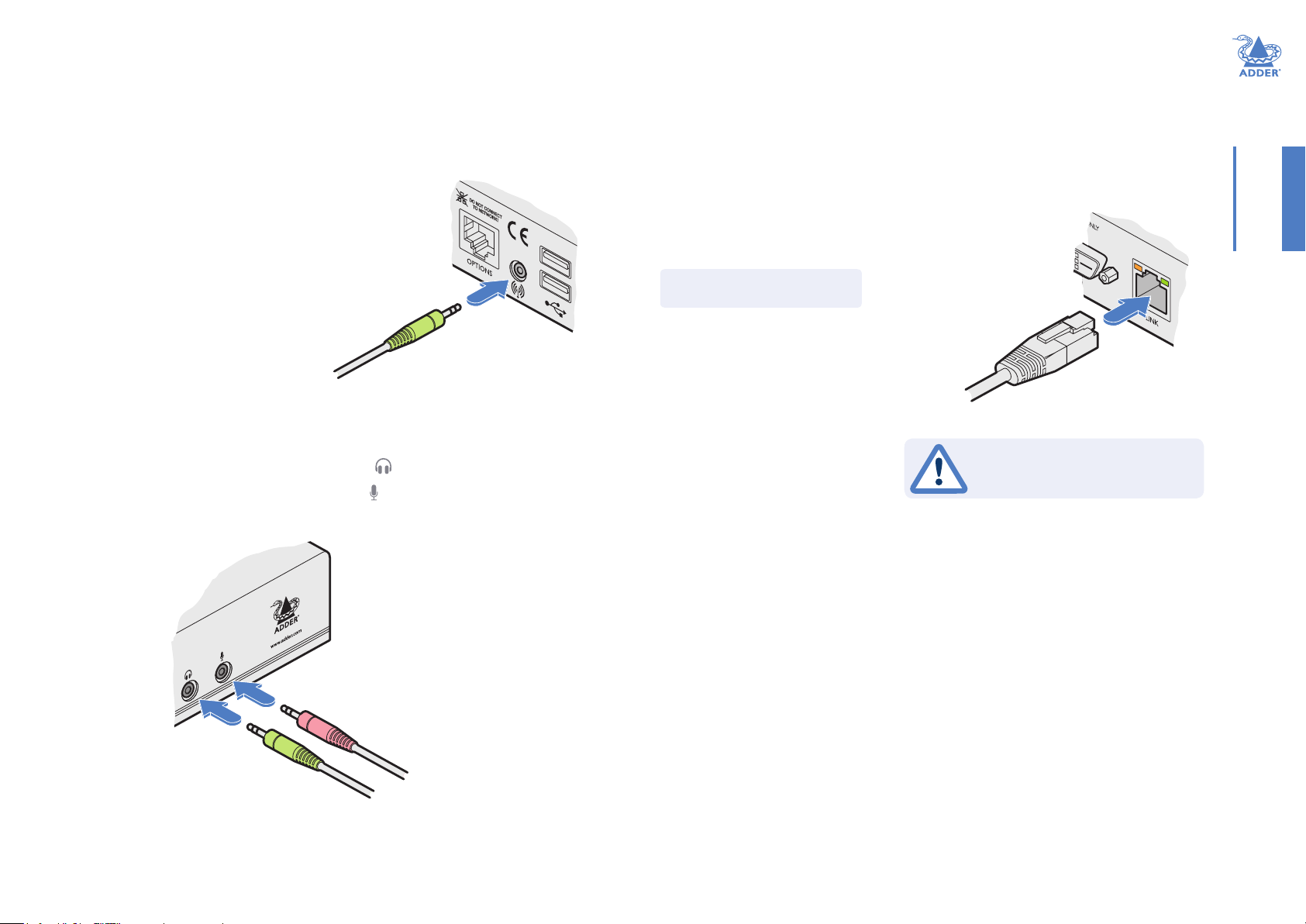
Console connections: Audio
The DDX-USR module supports stereo speakers, headphones and also a microphone
port. All audio devices are presented at the linked host computer as USB audio devices.
Note: In multi-head installations, the audio devices must be attached only to the DDX-USR
module that drives the main display.
To connect your speakers
1 Connect your speakers to the audio line out socket on
the user module rear panel.
Console connections: Data link
Each DDX-USR module is linked via shielded (S/FTP or S/STP) CAT6a or CAT7 cable
either to a central DDX switch module or directly to a DDX-CAM module (for a single
system installation) - do not exceed 50 metres (164 feet).
To link the DDX-USR module
1 Connect a shielded (S/FTP or S/STP) CAT6a or CAT7 cable to the LINK socket on
the rear panel of the DDX-USR module. Connect the other end of the cable to either a
DDX switch or directly to a DDX-CAM computer module.
INSTALLATIONCONFIGURATIONOPERATION
Note: Do not use unshielded
cables with the DDX modules.
From your speakers
To connect your headphones/microphone
1 Connect your headphones to the socket labeled on the user module front panel.
2 Connect your microphone to the socket labeled on the user module front panel.
From your microphone
From your headphones
Shielded CAT6a or CAT7 link
from DDX switch or DDX-CAM
This is NOT an Ethernet/network
port and must NEVER be connected
to any networking equipment.
Console connections: Options port
The options port is reserved for future use.
FURTHER
INFORMATION
INDEX
12

Console connections: Powe r
There is no on/off switch on the DDX-USR module, so operation begins as soon
as power is applied. The supplied power adapter uses a locking-type plug to help
prevent accidental disconnections; please follow the instructions given right whenever
disconnecting a power adapter.
To connect the power adapter
1 Attach the output plug of the supplied power adapter to
the power input socket on the rear panel of the DDX-USR
module.
From the
power adapter
2 Connect the IEC connector of the supplied country-specic power cord to the socket
of the power adapter.
To disconnect the power adapter
1 Isolate the power adapter from the mains supply.
2 Grasp the outer body of the power adapter plug
where it connects with the module.
3 Gently pull the body of the outer plug away from
the module. As the body of the plug slides back,
it will release from the socket and you can fully
withdraw the whole plug.
Gently pull back the plug outer
body to release the lock
IMPORTANT: Please read and adhere to the electrical safety information
given within the Safety information section of this guide. In particular, do not
use an unearthed power socket or extension cable.
Note: Both the modules and the power supplies generate heat when in operation and will
become warm to the touch. Do not enclose them or place them in locations where air cannot
circulate to cool the equipment. Do not operate the equipment in ambient temperatures
exceeding 40 degrees Centigrade. Do not place the products in contact with equipment whose
surface temperature exceeds 40 degrees Centigrade.
INSTALLATIONCONFIGURATIONOPERATION
FURTHER
INFORMATION
3 Connect the power cord to a nearby main supply socket.
INDEX
13
Conguration
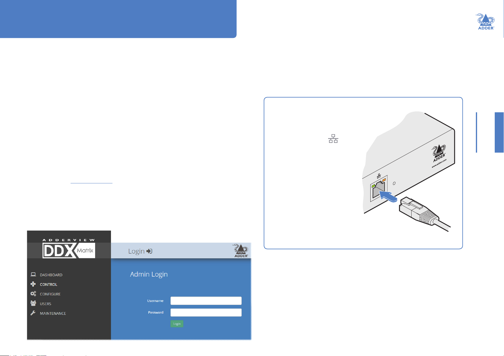
ACCESSING DDX MATRIX
DDX switches are congured via their network connections using an intuitive browserbased application, called DDX Matrix. This secure, password protected application is
accessible by any authorized user, located anywhere.
To access DDX Matrix
1 Use a computer that is directly or indirectly (i.e. via a network switch) connected to
the DDX switch. If you need to make a temporary connection, see right Ü
2 Run a web browser on your computer and enter the IP address of the DDX switch.
The DDX switch uses the Universal Plug and Play (UPnP) protocol to attempt contact
with a valid DHCP server to determine a suitable IP address. If a DHCP server cannot
be located then the switch will automatically fall back to a link-local IP address (in the
range 169.254.1.0 thru 169.254.254.255).
Whichever method the switch uses, the initial IP address can be discovered either:
• Using the Windows network browser (of a computer connected to the same sub
network or directly to the switch), or
• In the lower right corner of the OSD screen (of a console connected to one of the
user ports) see Viewing the OSD.
Note: For security, DDX Matrix uses HTTPS by default with a self-signed certicate - Please
ignore any warnings that may be displayed by your web browser.
3 If requested, enter your username and password to log on.
Note: The default username and password are admin and password respectively.
The opening page of the DDX Matrix should be displayed:
INSTALLATIONCONFIGURATIONOPERATION
To temporarily connect a computer to the network port
1 If you need to make a temporary connection for
conguration purposes, use a standard patch
cable (cross-over or straight connections are
both supported) to link the Ethernet
10/100 network port ( ) on the
front panel of the DDX switch to
your computer’s network port.
Temporary link from
your computer
FURTHER
INFORMATION
14
INDEX

USING DDX MATRIX
The Dashboard page
Once you have successfully logged in, DDX Matrix will show the dashboard page to
provide a general overview of your DDX installation. You can also re-display this page by
clicking the Dashboard entry in the menu:
INSTALLATIONCONFIGURATIONOPERATION
Information and options are
displayed within the main
section of the page.
Some items will provide
further popup information
when you hover your mouse
pointer over them.
Click the required menu
item to reveal the available
page choices.
Colors and symbols are used to provide quick visual feedback:
Operational with a valid video signal
Operational but rmware upgrade suggested
Not useable, rmware upgrade required
Disconnected
Note: An icon showing orange is currently being upgraded
Note: It is not possible to leave DDX Matrix open for more than 24 hours.
Click a heading to reorder
the whole list in ascending
or descending order
according to the entries
within the chosen column.
FURTHER
INFORMATION
Hover your mouse over an icon to
see more information:
INDEX
15

Quick guide to creating a new installation
When creating a new DDX installation there are various conguration tasks that need to be completed
within DDX Matrix. This page provides a recommended ‘to do list’ of the stages that you need to perform.
Primary tasks
• Congure the networking details for the DDX switch See Congure > Central Switch > Network
• Ensure that the EDID denitions are appropriate for your installation See Congure > Central Switch > Manage EDIDs
If additional EDID denitions are required for your installation, you can clone new
denitions from connected video displays and add these to the list of available denitions See Add EDID
• Add the required consoles (either before or after they are connected) See Congure > Consoles
By default the DDX switch provides 20 computer ports along its rear panel and
10 user ports along its front panel. If necessary, these standard arrangements can be
changed to suit your installation. See Reallocating ports
• Determine the access permissions for each console See Access permissions
• Add your computers (either before or after they are connected) See Congure > Computers
• Add the users and dene their login details See The Users Page
Secondary tasks
• Optionally make changes to the OSD settings See Congure > Central Switch > OSD Settings
• Add description and location details for the switch See Congure > Central Switch > General
INSTALLATIONCONFIGURATIONOPERATION
16
FURTHER
INFORMATION
INDEX

The Control page
The Control page provides a Connection map that allows the admin user to view and
affect how consoles are connected to the various computers. This page is particularly
useful when managing video-only installations.
To connect a console
1 Click the down arrow on the console entry to reveal the list of
computers that it is authorized to access.
2 Click the appropriate connection icon adjacent to the required
computer:
•
View only - console user can view a computer’s
output but not alter it,
•
Shared access - console user can view and
control a computer along with other consoles,
•
Exclusive - multiple console users can view a
computer but only one can control it,
or
INSTALLATIONCONFIGURATIONOPERATION
•
Private - console user can view and control the
computer privately while other users are locked out.
For further details, see Access permissions.
3 You can change the connection method at any time by clicking
the down arrow again and choosing an alternative connection
option.
To disconnect a console
1 Click the button in the lower left corner of the console entry
that you wish to disconnect.
FURTHER
INFORMATION
INDEX
17

The Congure pages
The Congure menu option expands when clicked to reveal three sub-sections:
• Central Switch - settings related directly to the DDX switch.
• Consoles - settings related to the DDX-USR modules and their connected peripherals.
• Computers - settings related to the DDX-CAM modules and their host computers.
Central Switch > General
Basic descriptive settings for the DDX switch. These are most useful when multiple DDX
installations are being managed; labelling each installation as you go is a good habit to get
into:
• Description - a further opportunity to add more information about the switch.
• Location - a useful feature if you have multiple DDX switches distributed around.
• System Default EDID - determines the default EDID to use for the installation.
• Ignore Firmware Mismatch - when set to On, this overrides the checks that are made to
ensure all modules are running compatible rmware versions. This override should be
used in exceptional circumstances only.
• Firmware Ver sion - shows the rmware version of the DDX switch.
• Recovery Version - shows the version of the DDX switch recovery image.
• Admin UI Version - shows the version of the DDX Matrix admin user interface.
These
items are
shown only
when the
Maintenance
> Settings
> Web
UI Mode
is set to
Advanced.
Central Switch > Network
All of the key settings for the network capabilities of the DDX switch are here:
• DHCP - allows you to use DHCP (Dynamic Host Conguration Protocol)
to automatically determine all network settings or set them manually.
When set to On, the next three options are not editable.
• IP Address - set the IP address for the switch.
• Net Mask - set a subnet mask to accompany the IP address.
• Gateway - optionally dene a suitable address for a gateway device.
• MAC Address - displays the unique (and xed) MAC address for the switch.
• HTTP Server - when ON, switches to the use of insecure HTTP for web
admin - switch reboot required. IMPORTANT: Do not enable this
option when the switch is connected to external networks.
• Network Service Discovery - when set to Disabled, the switch will not
announce its presence on the network and will not be discoverable using
the Windows network browser on a network-connected computer.
INSTALLATIONCONFIGURATIONOPERATION
FURTHER
INFORMATION
INDEX
18

INSTALLATIONCONFIGURATIONOPERATION
Central Switch > OSD Settings
Options related to the on screen display are
presented in this section:
• Thumbnails - when set to Off, this option will
hide the thumbnail views of each computer
within each user’s OSD main page.
• Auto Layout - when set to Off, this option
will maintain a 5x5 grid for the displayed
computers within the OSD main page,
regardless of the number of available
computers. When set to On, the OSD view
grid will be re-scaled accordingly.
• Display System Info - when set to On, the
current IP address and rmware version
details for the DDX switch will be shown in
the lower right corner of the OSD.
Central Switch > Manage EDIDs
This page lists the EDID (Extended Display Identication Data)
proles that are currently available:
• EDID - shows the resolutions and refresh rates for all proles
that are currently stored.
• Type - indicates where each EDID prole originated: Fixed
EDIDs are included within the switch rmware and cannot be
removed. User EDIDs are those that have been cloned from
particular video displays attached to DDX-USR modules -
these can be deleted if required. On the main Central Switch
> General page you can select the ‘Default System EDID’
from the list of xed and user EDIDs.
• Originating Port - indicates which switch port supplied each
user EDID.
• Active Transmitter Por ts - indicates which transmitters (if any)
are currently using each EDID.
Note: The DDX switch will modify the EDID, if a Dual link monitor
is connected, to list only the video resolutions that it is capable of
supporting.
Add EDID
If additional EDID denitions are required for
your installation, you can clone new denitions
from connected video displays and add these to
the list of available denitions.
Click the [+] icon to begin collecting a new EDID
from a display attached (via a DDX-USR module)
to one of the switch ports.
Click the EDID dropdown list and choose the
appropriate receiver (DDX-USR module) from
which you wish to clone a new EDID prole. Then
click the Add EDID button.
For details about applying an EDID to a particular
computer, see Congure > Computers >
Transmitters.
FURTHER
INFORMATION
INDEX
19

Congure > Consoles
A Console is a collective term for a set of peripheral devices arranged around one or more
DDX-USR modules. This page lists all registered consoles:
Click a heading to reorder the whole list in
ascending or descending order according
to the entries within the chosen column.
In addition to the Name and Description, other columns provide the following details and
options for each console entry:
• Ports - each DDX-USR module connects to a single port on the DDX switch. This
column lists the port(s) used by the DDX-USR module(s) associated with each
console. Two or more DDX-USR modules can be combined to form multi-head
consoles, each connecting to separate ports.
Note: For consoles with multiple displays (multi-head), additional user console ports are
required. If there are no spare user console ports available then any unused computer ports
on the rear panel can be deleted in order to free them up as spares. See Reallocating ports.
• OSD Mouse Launch - when set to On, allows the console user to invoke the on Screen
Display by holding down their center mouse button and then clicking the right button.
• Connected Computer - shows to which computer the console is currently connected.
• Current Access Mode - indicates how the console is currently connected to the listed
computer: = View only, = Shared access, = Exclusive, = Private
• Tick box - Allows you to tick all required console entries and then remove them
collectively using the Delete Selected button.
Edit
Click an entry to view/edit its details. See Congure > Consoles > Edit an entry
Add new
Click the [+] icon to begin adding a new console, either before or after
connecting the DDX-USR module(s):
• Name - the main identier for the new console.
• Description - a further opportunity to add more information.
• OSD Mouse Launch - (see description left).
• Port - add the port number (located on the main DDX switch) used by the
DDX-USR module associated with this console. For multi-head consoles,
ensure that the port used by the primary DDX-USR module (the one that
has the primary display and peripherals attached) is the rst one to be
dened. If a chosen port is already used, a warning will be displayed, see
Reallocating ports.
• Access Permissions - click the [+] button to select one or more computers
that this console will be permitted to access. For each computer choose
the appropriate access permissions (see Access permissions) : = View
only, = Shared access, = Exclusive, = Private
• Add Console - click to save your settings.
INSTALLATIONCONFIGURATIONOPERATION
FURTHER
INFORMATION
INDEX
20

Congure > Consoles > Edit an entry
Click on an entry within the Congure > Consoles list to display this page. Here you can
edit the conguration details for a chosen console.
Edit
• Name - the main identier for the console.
• Description - a further opportunity to add more information about the
console.
• OSD Mouse Launch - when set to On, allows the console user to invoke
the on Screen Display by holding down their center mouse button and
then clicking the right button.
• Ports - shows the user port number(s) (located on the main DDX switch)
used by the DDX-USR module(s) associated with this console. For
multi-head consoles, ensure that the port used by the primary DDX-USR
module (the one that has the primary display and peripherals attached) is
the rst one to be dened. If a chosen port is already used, a warning will
be displayed, see Reallocating ports.
• Access Permissions - choose which computers this console is permitted to
access. For each computer choose one or more of the four icons to set
the access permissions:
•
•
•
or
•
For further details, see Access permissions.
View only - console user can view a computer’s output but not
alter it,
Shared access - console user can view and control a computer
along with other consoles,
Exclusive - multiple console users can view a computer but
only one can control it,
Private - console user can view and control the computer
privately while other users are locked out.
INSTALLATIONCONFIGURATIONOPERATION
FURTHER
INFORMATION
When you have made your changes, click the Update button at the foot of
the page.
INDEX
21

Congure > Consoles > Receivers
At the heart of each console (the collective term for a set of peripherals connected to
the DDX system) is a receiver called a DDX-USR module.
Click a heading to reorder the whole list in
ascending or descending order according
to the entries within the chosen column.
This page shows various details for each DDX-USR module:
• Firmware - the current internal software version for each DDX-USR module.
• Monitor No - an index number for each video display. The rst monitor for any console will be
indexed as ‘1’. Where a console has more than one video display associated with it (by using
additional DDX-USR modules), this column will show ‘2’, ‘3’, etc. against the secondary, tertiary, etc.
DDX-USR module(s).
• Monitor model - indicates the video display model as reported to the DDX-USR module to which it is
connected.
• Unique ID - (shown only when the Maintenance > Settings > Web UI Mode is set to Advanced) this
column displays the unique identier hardwired into every DDX-USR module.
Click a receiver entry to view the conguration details of the
DDX switch port to which it is connected.
Within this page it is possible to reboot and/or recover a receiver.
Recovering a receiver
This option (shown only when the Maintenance > Settings > Web
UI Mode is set to Advanced) is used to reprogram a receiver that
has failed during a rmware upgrade. Once the Recover Receiver
button is clicked, you will be asked to power cycle the respective
receiver, whereupon it will boot up into recovery mode. Then
you will asked to click a Reprogram button to commence the
operation.
INSTALLATIONCONFIGURATIONOPERATION
FURTHER
INFORMATION
INDEX
22

Congure > Computers
This page lists the computer systems that are connected to the DDX switch unit via
individual DDX-CAM modules:
Click a heading to reorder the whole list in
ascending or descending order according
to the entries within the chosen column.
In addition to the Name and Description, the columns also provide the following useful details for each
computer entry:
• Port(s) - each DDX-CAM module connects to a single port on the DDX switch. This column lists the
port(s) used by the DDX-CAM module(s) associated with each computer. Two or more DDX-CAM
modules can be combined to support extra displays (multi-head), each connecting to a separate port.
Three of the user console ports (21 to 23) can be changed into computer ports, if there are fewer
user consoles within your installation. See Reallocating ports.
• Thumbnail - indicates whether a thumbnail image of the computer’s video output will be shown on the
OSD screen for each user. If disabled (unticked), a black image will be shown in the OSD screen.
• Primary Console - indicates the console that currently has control of the computer.
• Connected Consoles - lists all consoles to which each computer is attached.
• Current Access Mode - indicates how the computer is currently being accessed by the listed console:
= View only, = Shared access, = Exclusive, = Private
• Tick box - Allows you to tick all required computer entries and then remove them collectively using
the Delete Selected button.
Add new
Click the [+] icon to begin adding a new computer,
either before or after connecting the DDX-CAM
module(s):
• Name - the main identier for the new computer.
• Description - a further opportunity to add more
information about the computer.
• Computer Number - provides a list of the remaining
vacant computer numbers that you can associate
with your new entry. The chosen number will
determine the position of this computer in the
OSD screen and also the hotkey (Ctrl+Alt+n)
used to access it. You can swap the number used
with other computers within the edit page.
• Ports - Add one or more port numbers used by
the DDX-CAM module(s) associated with this
computer.
Edit
Click an entry to view/edit its details and options.
See Congure > Computers > Edit an entry
INSTALLATIONCONFIGURATIONOPERATION
FURTHER
INFORMATION
INDEX
23

Congure > Computers > Edit an entry
This page allows you to edit the conguration details for a chosen computer.
Edit
• Name - the main identier for the computer.
• Description - a further opportunity to add more information about
the computer.
• Computer Number - displays a list of computer numbers (used and
vacant) that you can associate with this entry. The chosen number
will determine the position of this computer in the OSD screen
and also the hotkey (Ctrl+Alt+n) used to access it. If you choose a
computer number that is already used by another computer, then
it and the existing number held by this computer will be swapped
over.
• Port(s) - shows the one or more port numbers used by the DDX-
CAM module(s) associated with this computer. For multi-head
computers, ensure that the port used by the primary DDX-CAM
module (the one linked to the primary video output) is the rst
one in the list. Three of the user console ports (21 to 23) can be
changed into computer ports, if there are fewer user consoles
within your installation. See Reallocating ports.
• Thumbnail - indicates whether or not a thumbnail view of this
computer’s video output should be shown OSD screen for each
user.
• Primary Console - indicates the primary console that is connected to
this computer.
• Connected Consoles - indicates other consoles that are also
connected to this computer.
• Current Access Mode - indicates the access mode (e.g. View Only,
Shared, Exclusive, etc.) that is currently being used for this
computer.
• Transmitters - lists the transmitters (DDX-CAM modules) that are
serving this computer.
When you have made your changes, click the Update button.
INSTALLATIONCONFIGURATIONOPERATION
FURTHER
INFORMATION
INDEX
24
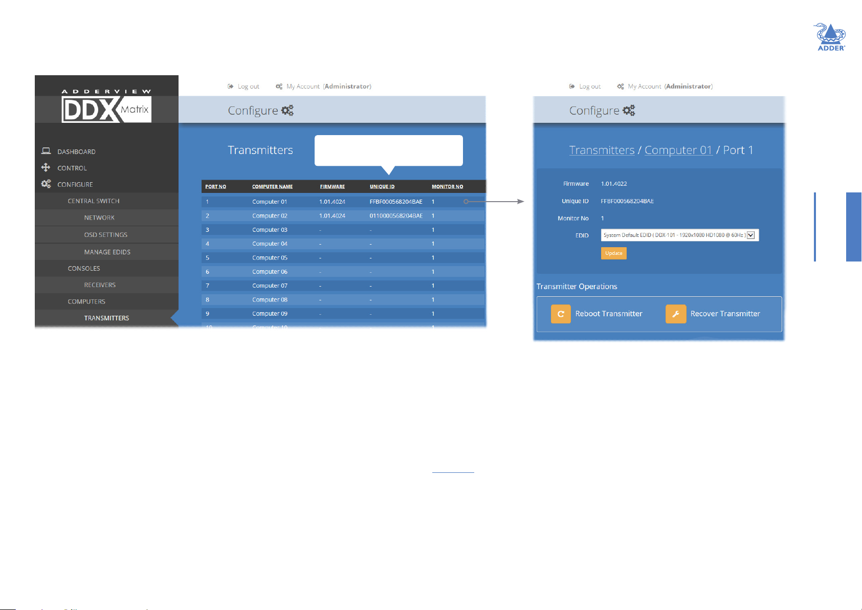
Congure > Computers > Transmitters
Each computer connects to a DDX-CAM transmitter module. This page lists each
DDX-CAM module and their key details:
Click a heading to reorder the whole list in
ascending or descending order according
to the entries within the chosen column.
INSTALLATIONCONFIGURATIONOPERATION
This page lists various details for each DDX-CAM module:
• Computer Name - the given name for each connected computer.
• Firmware - the current internal software version for each DDX-CAM
module.
• Monitor No - an index number for each video display port. The rst port for
any computer will be indexed as ‘1’. Where a computer has more than one
video display connected it (by using additional DDX-CAM modules), this
column will show ‘2’, ‘3’, etc. against the secondary, tertiary, etc. DDX-CAM
module(s).
• Unique ID - (shown only when the Maintenance > Settings > Web UI Mode
is set to Advanced) this column displays the unique identier hardwired
into every DDX-CAM module.
Click a transmitter entry to view the conguration details of its port on the DDX switch.
Within this page it is possible to reboot and/or recover a transmitter.
Applying a different EDID
If a computer needs to use an EDID prole that
differs from the one being used as the default
System EDID, use these steps:
1 If necessary, clone the required EDID - see
Add EDID.
2 View the Congure > Computers >
Transmitters page and click on the required
computer entry (to show the page above).
3 Select the appropriate entry from the EDID
drop down list.
4 Click the Update button.
Recovering a transmitter
This option (shown only when
the Maintenance > Settings > Web
UI Mode is set to Advanced) is
used to reprogram a transmitter
that has failed during a rmware
upgrade. Once the Recover
Transmitter button is clicked, you
will be asked to power cycle the
respective transmitter, whereupon
it will boot up into recovery mode.
Then you will asked to click a
Reprogram button to commence
the operation.
FURTHER
INFORMATION
INDEX
25
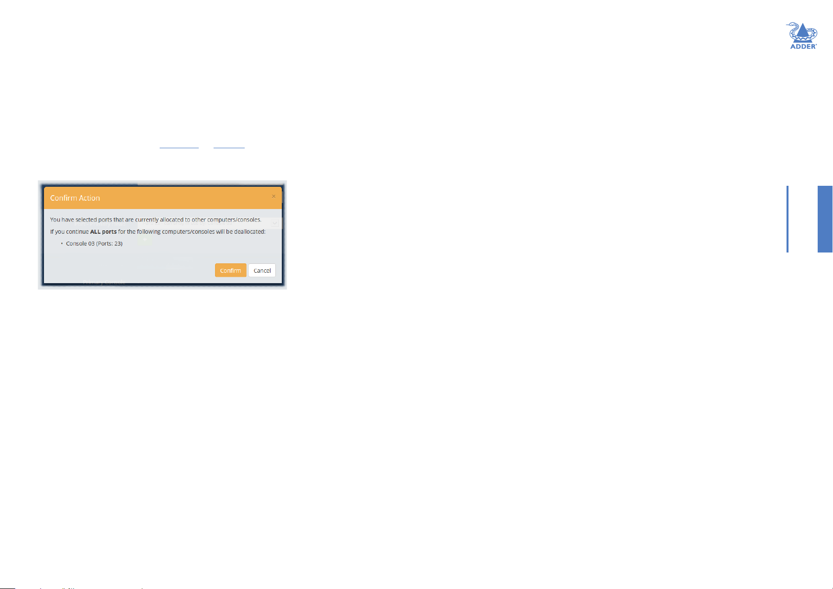
Reallocating ports
By default the DDX switch provides 10 user console ports on its front panel and 20
computer ports along its rear panel, however, these designations are not xed. If your
installation requires a greater number of computers or has a need for more user
consoles, you can alter the allocation of these standard ports to suit:
• Any of the 20 rear panel computer ports can be reallocated as user console ports, or
• Three of the front panel ports (labeled 21 to 23) can be used as computer ports.
To reallocate a port that is already being used
1 While creating (or editing) a computer or console entry, choose the required port.
If the port is already being used, when you click the Update button, you will be
presented with a warning such as the following:
2 Click the Conrm button. The chosen port will rst be de-allocated from its existing
relationship and then paired to your device. The device that originally used the port
will be left without a port allocation and will need separate attention.
Note: If you reallocate any port from a multi-head computer/console this will cause all ports
associated with that computer/consoles to be de-allocated.
INSTALLATIONCONFIGURATIONOPERATION
26
FURTHER
INFORMATION
INDEX

The Users page
This page lists all registered users and allows the admin user to add, edit and delete
entries, as required.
Note: When changes are made to user details, you are recommended to make a backup le.
INSTALLATIONCONFIGURATIONOPERATION
Add new
Click the [+] icon to begin adding a new user.
Edit
Click a user entry to edit its details.
Note: It is not possible to delete the Administrator account if it is
the only administrator account remaining.
FURTHER
INFORMATION
INDEX
27
The Maintenance pages
The Maintenance section contains three pages: Diagnostics, System Operations and
Settings.
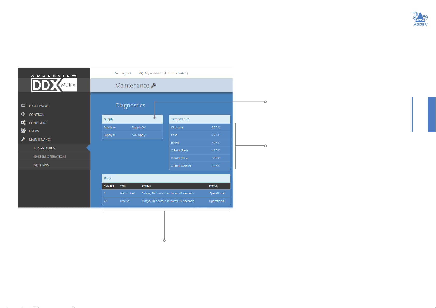
Maintenance > Diagnostics
This page provides important feedback on power inputs (and switch Temperatures). The
temperature information is displayed only when the Maintenance > Settings > Web UI
Mode is set to Advanced.
INSTALLATIONCONFIGURATIONOPERATION
This section indicates the
status of the mains power
input(s).
These items are only shown when
Settings > Advanced Mode On is chosen.
This section indicates the current
temperature readings within the DDX
switch for the following:
• The processor core,
• The internal case area,
• The main circuit board,
• The red, green and blue video switches.
This section lists the currently active ports,
their uptime and status.
FURTHER
INFORMATION
INDEX
28
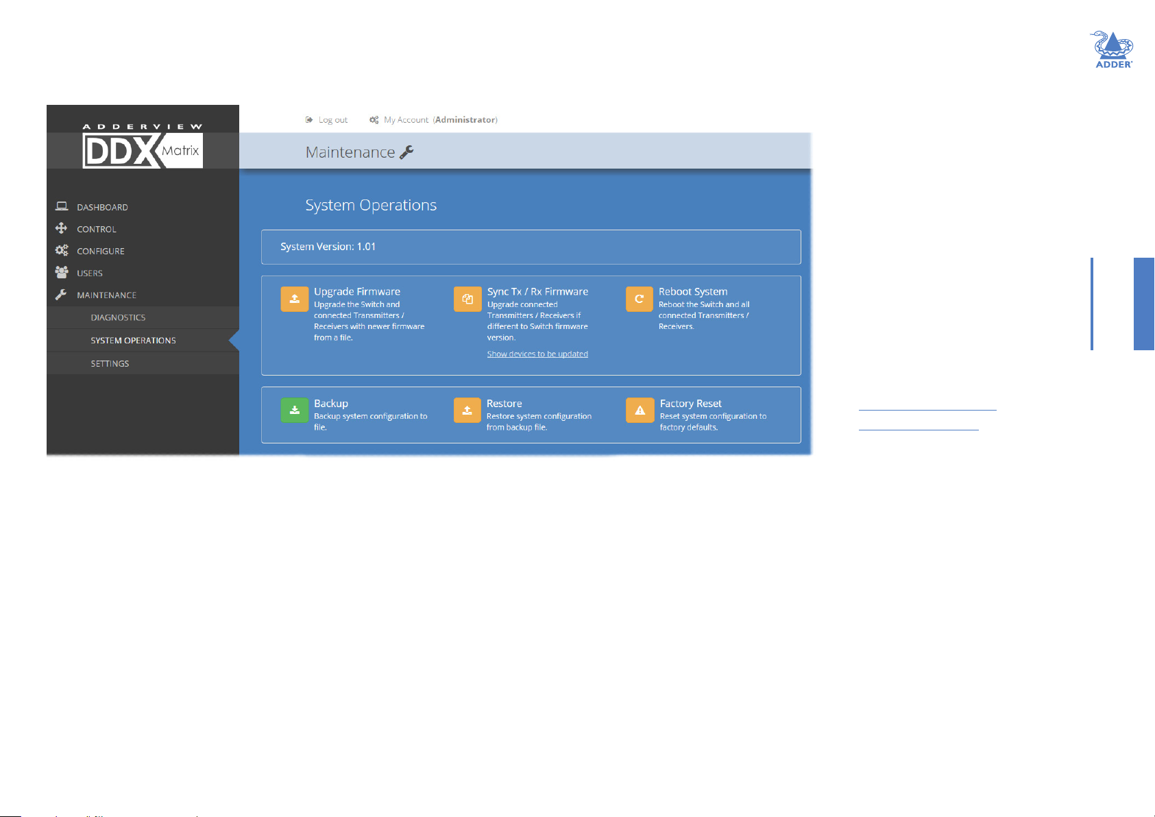
Maintenance > System Operations
This page provides a selection of important system operations that may be required at
various times.
INSTALLATIONCONFIGURATIONOPERATION
Recovering an unresponsive
transmitter or receiver
If a rmware upgrade to a transmitter
or receiver has failed, the unit may
become unresponsive. If so, please
follow the advice provided in other
sections of this guide:
• Recovering a transmitter
• Recovering a receiver
Upgrade Firmware
Upgrades the rmwares of the DDX
switch and all connected modules to the
latest version. Conrmation is required
once this button is clicked.
Backup
Saves a copy of the DDX Matrix system
conguration to a le. Backup les are
stored on the computer viewing DDX
Matrix.
Sync Tx/Rx Firmware
Upgrades the rmwares of all connected
modules to match that of the main switch.
Conrmation is required once this button is
clicked.
Note: Be sure that the DDX switch has the latest
rmware installed before using this option.
Restore
Restores the DDX Matrix system
conguration from a backup le. A le dialog
will be displayed to allow you to choose the
lename and location.
Reboot System
Performs a complete reboot of
the entire DDX system, including
the switch and all modules.
Conrmation is required once
this button is clicked.
Factory Reset
Returns all DDX system
conguration settings back to
their factory defaults.
FURTHER
INFORMATION
INDEX
29
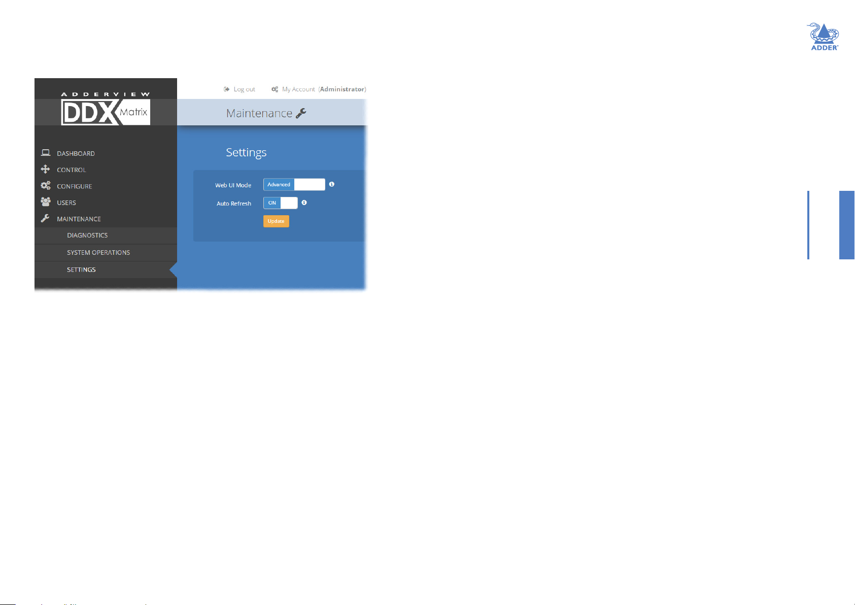
Maintenance > Settings
This page provides options related to the user interface. When you make a change, you
need to click the Update button to save it.
Web UI Mode
When this option is set to Advanced, extra details are shown on
certain pages, such as:
• Congure > Central Switch > General
• Congure > Consoles > Receivers
• Congure > Computers > Transmitters
• Maintenance > Diagnostics
Auto Refresh
When this option is set to On, the Dashboard, Control and
Diagnostic pages will automatically update their contents every
few seconds.
Update
Click this button to save and enact any changes made to options.
INSTALLATIONCONFIGURATIONOPERATION
30
FURTHER
INFORMATION
INDEX

RESETTING AND RECOVERING
There may be rare occasions when the main switch or a module needs to be given a hard reset. The DDX switch
and DDX-USR module both have concealed reset buttons for this purpose. You need to use a narrow implement
(e.g. a straightened-out paper clip) to press-and-hold the recessed reset button on the front panel:
DDX switch
DDX switch > Boot into recovery image
This procedure may be necessary if an attempted rmware upgrade has failed. The
switch will load the factory default conguration, requiring you to log-in using the factory
default username/ password and a freshly determined IP address (see Accessing DDX
Matrix). You will be required to accept a new temporary SSL certicate when accessing
the web interface. Note: All conguration data (e.g. users, consoles, computers, networking, etc.)
will be retained.
1 Press-and-hold the recessed reset button for ten seconds until the STS (Status)
indicator begins to ash slowly.
2 Release the reset button. The STS indicator will go out and the switch will boot itself
using the recovery image. The STS indicator will now begin to ash again to indicate
that it is running from the recovery image (a red banner will also be shown at the top
of the DDX Matrix screen).
3 When you are sure of operating conditions, such as having good power stability,
proceed once again with the rmware upgrade.
DDX switch > Reset
This procedure may be necessary if the switch has become unresponsive. Note: All
conguration data (e.g. users, consoles, computers, networking, etc.) will be retained.
1 Press-and-release the recessed reset button. The switch will reboot.
DDX-USR module
DDX-USR module > Boot into recovery mode
This procedure may be necessary if an attempted rmware upgrade has failed. For such
a situation the DDX-USR module always retains a recovery image that will return the unit
to a working condition, prior to reattempting a rmware upgrade.
1 Press-and-hold the recessed reset button for ten seconds until the PWR indicator
begins to ash quickly.
2 Release the reset button.
3 When you are sure of operating conditions, such as having good power stability,
proceed once again with the rmware upgrade.
DDX-USR module > Reset
This procedure may be necessary if a DDX-USR has become unresponsive.
1 Press-and-release the recessed reset button. The DDX-USR module will reboot.
Recovering an unresponsive transmitter or receiver
If a rmware upgrade to a transmitter or receiver has failed, the unit may become
unresponsive. If so, please follow the advice provided in other sections of this guide:
• Recovering a transmitter
• Recovering a receiver
INSTALLATIONCONFIGURATIONOPERATION
FURTHER
INFORMATION
INDEX
31

Operation
The DDX system is designed to be transparent in operation. A simple OSD (On Screen
Display) interface allows each user to view and select from the available host computers.
VIEWING THE OSD
To view the OSD, either:
• From a console keyboard, press CTRL + ALT + M, or
• From a console mouse, press and hold the middle button and then press the right button.
The OSD will be displayed:
Choosing a computer
To choose a computer using the mouse
1 Display the OSD from your console using either of the methods shown left.
2 Hover the mouse pointer over the required screen image. A set of popup connection
icons will be displayed:
•
•
•
or
•
For more details, see Access permissions.
Note: If an icon is grayed out, that access method is not available.
3 Click the required connection method. The video output from the chosen computer
will be displayed full screen and you can use it as normal.
Note: When viewing the OSD, you can also click outside a computer thumbnail to return to your
previous computer (with your last access permissions if still available).
To choose a computer using hotkeys (without viewing the OSD)
• Press and hold Ctrl + Alt and type the number of the required computer. The video
output from the chosen computer will be displayed full screen and you can use it as
normal.
Note: Shared access mode is always used when the computer choice is made via hotkeys.
View only - you can view a computer’s output but not alter it,
Shared access - you can view and control a computer along with other
consoles,
Exclusive - multiple users can view a computer but only one (the rst to
make connection) can control it,
Private - you can view and control the computer privately while other users
are locked out.
INSTALLATIONCONFIGURATIONOPERATION
FURTHER
INFORMATION
Thumbnail images
The outputs of the available host computers will
be displayed within live thumbnail images.
Note: If video is not available for a computer, or the
Thumbnails option has been set to OFF, a black image
will be shown. See Central Switch > OSD Settings.
Switch information
The additional information in the lower right corner,
including the current IP address setting, rmware
version and any current rmware upgrade warnings/
errors, is displayed within the OSD screen, providing the
Display System Info option is set to ON.
See Central Switch > OSD Settings.
INDEX
32

USING AUDIO
The DDX system fully supports stereo audio, with all audio devices being presented
at the linked host computer as USB audio devices. There are slight differences in audio
operation between DDX devices acting in a simple extender arrangement (without the
use of a DDX switch) and a full DDX matrix installation.
Using audio in a simple extender installation
The audio is presented to the computer’s operating system as a USB headset with
controls for input level, input mute, input AGC, sidetone level, sidetone mute, output
level, output mute and output balance. The audio device is permanently presented to the
computer when the DDX-CAM module powers up.
You can adjust the audio features using all of the standard operating system controls.
Note: Due to the architecture of the Codec, adjusting the input (microphone) level or muting the
input (microphone) will also affect the sidetone level and mute.
Using audio in a full DDX matrix installation
Audio functionality is enabled by default on all computers. For multi-head computers,
audio is only enabled for the primary transmitter, although two audio devices will be
presented to the computer, one for each transmitter. For multi-head consoles, audio is
only enabled for the primary receiver.
Managing audio in multi-user situations
• In all connection modes, the audio output of the computer is routed to the receiver
from the transmitter.
• In View Only and Shared modes, the receiver input audio is ignored.
• In Exclusive and Private modes, the receiver input audio is routed to the transmitter.
Note: The above is equivalent to routing the output audio as per the video and the input audio
as per the USB (except in View Only and Shared modes, where the input audio stream is
ignored).
When viewing the OSD selection screen, input and output audio is suppressed.
The user who is currently in control of a computer can adjust the audio levels using the
standard operating system audio features; their changes will affect the audio for all other
users viewing the same computer. Additional users connected in View Mode, or additional
Shared Access users who don’t have control, can listen to the audio but at the volume
dictated by the main user. As a user switches between machines, their audio levels are
automatically adjusted to match their current connection.
INSTALLATIONCONFIGURATIONOPERATION
FURTHER
INFORMATION
INDEX
33

INDICATORS
The DDX switches, the DDX-CAM and DDX-USR modules contain various indicators
to provide you with status information.
DDX switch - Red front panel status indicators
The red status indicators on DDX switch front panels provide various key power and
operation feedback:
Power input A
This indicator will
be on when power
is supplied to power
socket A
Power input B
This indicator will
be on when power
is supplied to power
socket B
STS (Status)
On: Running primary
rmware image
1Hz ash: Running
backup rmware image
2Hz ash: Upgrade
mode engaged
ERR
Flashing: Either,
Power input failed or
internal error - refer
to the Maintenance >
Diagnostics page for
details
or
A rmware mismatch
has been detected
with one or more
connected devices -
refer to the Dashboard
page for details
DDX switch - Green and amber network status indicators
The green and amber status indicators on the network link port provide further
status information:
Amber
Off: 10 or 100Mbps
On: 1000Mbps
Green
Off: No link
Flashing: Network activity
On: Quiescent link
INSTALLATIONCONFIGURATIONOPERATION
34
FURTHER
INFORMATION
INDEX

DDX-USR module - Green and amber status indicators
The green and amber indicators on the link port of each DDX-USR (console/
user) module provide the following status information:
DDX-CAM module - Green and amber status indicators
The green and amber indicators on the link port of each DDX-CAM (computer)
module provide the following status information:
INSTALLATIONCONFIGURATIONOPERATION
Amber
Off: No power
Slow ashing: Power present but
either no video or
video not locked
On: Power present and
video locked
Green
Off: No power
Flashing: Power present but no data link
On: Power present and link established
DDX-USR module - Red front panel status indicators
The red indicators on the front panel of each DDX-USR (console/user) module
provide the following status information:
LNK
Off: No power or
no link
Flashing: Switch
refused link
connection due
to incompatible
rmware versions
On: Link established
USB
Off: No power or no active
USB connection
Flashing: USB connection is
contended in shared mode
(keyboard LEDs also ash)
On: USB is routed to a
DDX-CAM module, either via
the DDX switch or directly, in
a simple extender installation
VID
Off: No power
present or the
video is not locked
On: Power present
and video locked
PWR
Off: No power present
Slow ashing: A rmware
upgrade is being forced
by the DDX switch
Fast ashing: Receiver in
USB recovery mode
On: Power present
Amber
Off: No power
Slow ashing: Power present
but no video
On: Power present
and video locked
Green
Off: No power
Slow ashing: Power present but no data link
Fast ashing: A rmware upgrade is being forced by
either the DDX switch or a DDX-USR
On: Power present and link established
Special condition
Amber ashing and Green off: Software fault requiring the DDX-CAM module to be
recovered. See Congure > Computers > Transmitters.
FURTHER
INFORMATION
INDEX
Special condition
PWR on, Amber ashing and Green off: Software fault requiring the DDX-USR module to be
recovered. See Congure > Consoles > Receivers.
35

Further information
This chapter contains a variety of information, including the following:
• Getting assistance - see right
• Appendix 1 - Link cable interference protection
• Appendix 2 - Firmware upgrades for basic extender installations
• Safety information
• Warranty
• Radio frequency energy statements
GETTING ASSISTANCE
If you are still experiencing problems after checking the information contained within this
guide, then we provide a number of other solutions:
• Online solutions and updates – www.adder.com/support
Check the Support section of the adder.com website for the latest solutions and
rmware updates.
• Technical support – www.adder.com/contact-support-form
For technical support, use the contact form in the Support section of the
adder.com website - your regional ofce will then get in contact with you.
INSTALLATIONCONFIGURATIONOPERATION
FURTHER
36
INFORMATION
INDEX

APPENDIX 1 - LINK CABLE INTERFERENCE PROTECTION
While the Category rating (e.g. CAT 5e, CAT 6a, CAT 7, etc.)
determines the electrical performance of a cable, another vital part
of the overall cable specication is its protection from interference.
As cabling distances and data rates increase, so too does the
susceptibility to interference, from both external and internal
sources.
Proximity to other electromagnetic sources are the main external
threat and these can be subdued using overall screening that
surrounds all four of the cable pairs. However, interference is also
possible from neighbouring twisted pairs within the same cable
and this can be just as hazardous to data integrity. Such crosstalk is
countered by shielding each cable pair separately.
Within each Category rating, you can specify different
combinations of external screening and internal shielding to suit
the environment into which the link is being placed.
Interference protection codes
Interference protection is classied in the following manner:
Name Overall Screening Pair Shielding
U/UTP û û
F/UTP
U/FTP û
û
ü
U/UTP
INSTALLATIONCONFIGURATIONOPERATION
F/UTP
ü
U/UTP
Overall
screening
shielding
where
U = unshielded
F = foil shielding
S = braided shielding
PiMF = Pairs in Metal Foil
Note: Do not use unshielded
cables with the DDX modules.
Pair
Twisted
Pair
S/FTP
or S/STP
or PiMF
General cable anatomy
ü
Outer sheath
Overall screening
Pair shielding
ü
U/FTP
S/FTP
S/STP
PiMF
FURTHER
INFORMATION
INDEX
37

APPENDIX 2 - FIRMWARE UPGRADES FOR BASIC EXTENDER INSTALLATIONS
Extender systems (or individual DDX-USR units) can be upgraded using a USB stick if
required. This is carried out as follows:
1 Connect the DDX-USR to a compatible display and keyboard; optionally connect to a
DDX-CAM module using a Shielded CAT6a or CAT7 data cable to upgrade it at the
same time.
2 On the DDX-USR unit, insert a FAT32-formatted USB stick containing the extender
rmware upgrade le into one of the front USB ports. Note: The extender rmware
upgrade le must be in the root folder.
3 Apply power to the DDX-USR unit and DDX-CAM modules.
IMPORTANT: Ensure power remains uninterrupted throughout the upgrade process.
4 Press-and-hold the recessed reset button for ten seconds until the PWR indicator
begins to ash quickly, then release the reset button.
5 When prompted, type in the name of the extender rmware upgrade le and press
Enter.
6 Type Y or N as appropriate, when asked if an attached (DDX-CAM) transmitter unit
should also be upgraded.
7 The display will show the upgrade progress and conrmation message.
8 If successful the DDX-USR and DDX-CAM modules will automatically be rebooted
and the USB stick can be removed.
INSTALLATIONCONFIGURATIONOPERATION
FURTHER
38
INFORMATION
INDEX

SAFETY INFORMATION
• For use in dry, oil free indoor environments only.
• Warning - live parts contained within power adapter(s).
• No user serviceable parts within power adapter(s) - do not dismantle.
• Plug the power adapter(s) into socket outlets close to the module that they are
powering.
• Do not use an unearthed power socket or extension cable.
• Do not use a power adapter if its case becomes damaged, cracked or broken or if you
suspect that it is not operating properly.
• Replace the power adapter(s) with a manufacturer approved type only.
• If you use a power extension cord with the module, make sure the total ampere rating
of the devices plugged into the extension cord does not exceed the cord’s ampere
rating. Also, make sure that the total ampere rating of all the devices plugged into the
wall outlet does not exceed the wall outlet’s ampere rating.
• Do not attempt to service the modules yourself.
WARRANTY
Adder Technology Ltd warrants that this product shall be free from defects in
workmanship and materials for a period of two years from the date of original purchase.
If the product should fail to operate correctly in normal use during the warranty period,
Adder will replace or repair it free of charge. No liability can be accepted for damage due
to misuse or circumstances outside Adder’s control. Also Adder will not be responsible
for any loss, damage or injury arising directly or indirectly from the use of this product.
Adder’s total liability under the terms of this warranty shall in all circumstances be
limited to the replacement value of this product.
If any difculty is experienced in the installation or use of this product that you are
unable to resolve, please see the Getting assistance section.
INSTALLATIONCONFIGURATIONOPERATION
FURTHER
39
INFORMATION
INDEX

RADIO FREQUENCY ENERGY
A Category 5e (or better) twisted pair cable must be used to connect the units in order
to maintain compliance with radio frequency energy emission regulations and ensure a
suitably high level of immunity to electromagnetic disturbances.
All cables used with this equipment must be shielded in order to maintain compliance
with radio frequency energy emission regulations and ensure a suitably high level of
immunity to electromagnetic disturbances.
European EMC directive 2004/108/EC
This equipment has been tested and found to comply with the limits for a class A
computing device in accordance with the specications in the European standard
EN55032. These limits are designed to provide reasonable protection against harmful
interference. This equipment generates, uses and can radiate radio frequency energy
and if not installed and used in accordance with the instructions may cause harmful
interference to radio or television reception. However, there is no guarantee that
harmful interference will not occur in a particular installation. If this equipment does
cause interference to radio or television reception, which can be determined by turning
the equipment on and off, the user is encouraged to correct the interference with one
or more of the following measures: (a) Reorient or relocate the receiving antenna.
(b) Increase the separation between the equipment and the receiver. (c) Connect
the equipment to an outlet on a circuit different from that to which the receiver is
connected. (d) Consult the supplier or an experienced radio/TV technician for help.
FCC Compliance Statement (United States)
This equipment generates, uses and can radiate radio frequency energy and if not
installed and used properly, that is, in strict accordance with the manufacturer’s
instructions, may cause interference to radio communication. It has been tested and
found to comply with the limits for a class A computing device in accordance with
the specications in Subpart J of part 15 of FCC rules, which are designed to provide
reasonable protection against such interference when the equipment is operated in a
commercial environment. Operation of this equipment in a residential area may cause
interference, in which case the user at his own expense will be required to take whatever
measures may be necessary to correct the interference. Changes or modications not
expressly approved by the manufacturer could void the user’s authority to operate the
equipment.
INSTALLATIONCONFIGURATIONOPERATION
FURTHER
INFORMATION
Canadian Department of Communications RFI statement
This equipment does not exceed the class A limits for radio noise emissions from digital
apparatus set out in the radio interference regulations of the Canadian Department of
Communications.
Le présent appareil numérique n’émet pas de bruits radioélectriques dépassant les limites
applicables aux appareils numériques de la classe A prescrites dans le règlement sur le
brouillage radioélectriques publié par le ministère des Communications du Canada.
INDEX
40

Web: www.adder.com
Contact: www.adder.com/contact-details
Support: www.adder.com/support
INSTALLATIONCONFIGURATIONOPERATION
FURTHER
INFORMATION
Documentation by:
www.ctxd.com
INDEX
© 2016 Adder Technology Limited
All trademarks are acknowledged.
Part No. MAN-DDX-ADDER • Release 1.2
41

Index
A
Access permissions 3
Add EDID 19
Audio 33
Audio connections
console 12
Auto Refresh 30
B
Backup 29
C
Cable types 37
Category rating 37
Computer
choosing 32
Computer link
connecting 9
switch 9
Computers
congure 23
Congure pages 18
Consoles
congure 20
Control page 17
Crosstalk 37
D
Dashboard page 15
Data link
console 12
Data link connection
computer 8
DDX-CAM 8
DDX Matrix
accessing 14
DDX-USR switches 11
DHCP 18
Diagnostics 28
DisplayPort 8
DVI-D 8
E
EDID
applying 25
EDID management 11
Exclusive 17
F
Firmware upgrade
extenders 38
via switch 29
FTP 37
G
Gateway 18
H
Headphone connection 12
Hotkeys 32
HTTPS 14
HTTP Server 18
I
IEC connector 10
Ignore Firmware Mismatch 18
Indicators 34
modules 35
switch 34
Interference
protection 37
IP Address 18
M
MAC Address 18
Maintenance pages 28
Manage EDIDs 19
Microphone connection 12
Mode switches 14
N
Net Mask 18
Network link
connecting 9
switch 9
Network port
temporary connection 14
Network settings 18
O
OSD
viewing 32
OSD Settings 19
P
Password
default 14
PiMF 37
Port
designations 3
reallocation 26
Power connection
console 13
switch 10
Power disconnect 10
Primary console 20,21,23,24
Private 17
R
Reallocating ports 26
Reboot System 29
Receivers
congure 22
Recover
failed upgrade 31
receiver 22
transmitter 25
Recovering a receiver 22
Resetting 31
Restore 29
RJ-45 socket 9
S
Safety information 39
Screening 37
Settings 30
Shared access 17
Shielding 37
STP 37
Switches
DDX-USR 11
Sync Tx/Rx Firmware 29
System Default EDID 18
System Operations 29
T
Thumbnails 19,23
Transmitters
congure 25
U
Unique ID 22,25
Upgrade rmware 29,38
UPnP 14
USB
remote module 11
USB connection
computer 8
console 11
User console link
switch 9
Username
deafult 14
UTP 37
V
Video
remote module 11
Video connection
computer 8
console 11
View only 17
W
Warranty 39
Web UI Mode 30
INSTALLATIONCONFIGURATIONOPERATION
FURTHER
INFORMATION
INDEX
42
 Loading...