

Page 1

ADDERView® CCS-MV4228
Experts in
Connectivity
Solutions
KVM Switching
Solutions
User Guide
Page 2

Contents
Introduction
Welcome ................................................................................................................ 2
Technical specications ....................................................................................... 3
Supplied items ....................................................................................................... 4
Optional extras .....................................................................................................5
Installation
Connections .......................................................................................................... 6
Computer connections ................................................................................. 7
Console connections ..................................................................................... 8
Remote control connection ........................................................................9
Power connection ..........................................................................................9
Operation
Displaying windows ............................................................................................21
Switching between channels ............................................................................22
Managing windows .............................................................................................22
Entering and exiting system mode ...........................................................22
Taking control of a window ......................................................................22
Custom Preset Layouts ...............................................................................23
Resizing and moving windows ...................................................................23
Using Copy & Paste ...........................................................................................24
Using the COM Device mode ...................................................................24
Using the USB Device Mode ....................................................................24
INSTALLATION
CONFIGURATIONOPERATION
Conguration
Initial display setup .............................................................................................10
General conguration .......................................................................................10
Using with dual head computers ..............................................................10
Using the OSD ....................................................................................................11
Channel names ..............................................................................................11
Changing channel indicator colors ...........................................................11
Video Settings ...............................................................................................12
Channel Settings ...........................................................................................13
USB Settings ..................................................................................................14
Audio Settings ...............................................................................................15
Advanced Settings ........................................................................................16
System Information ......................................................................................17
Copy & Paste .......................................................................................................18
Installing the Copy & Paste driver ............................................................18
Enabling the COM Device mode ..............................................................18
Enabling the USB Device mode .................................................................19
CCS-MV upgrade process ................................................................................20
Further information
Getting assistance ..............................................................................................25
Appendix A - Hotkey commands ..................................................................26
Appendix B – Open Source Licenses ............................................................27
Index
FURTHER
INFORMATION
INDEX
1
Page 3

Introduction
WELCOME
Thank you for choosing the ADDERView™ CCS-MV4228 multi-viewer switch for
working simultaneously with up to eight computers. You can choose to view the
output of any computer on either a single 8-port display or dual 4-port displays. Focus
automatically changes between computers as the mouse pointer is moved into each
related window.
Features
• Automatic switching between ports without the need to press any buttons. Simply
move the mouse between windows.
• High quality 4K video resolution.
• Dual video outputs where the second output either duplicates the rst or extends
the desktop.
• Connects to either single or dual head computers.
• Analog audio with Hold feature.
• Digital audio with mixer function that combines output from multiple channel
inputs.
• Hi-Speed USB 2.0 port for isochronous and mass media devices.
• Clear channel identication to reduce the chances of operator error by displaying a
user dened name for each channel on the status display. The color of the channel
indicators may also be congured.
INSTALLATION
CONFIGURATIONOPERATION
Switching between computers can also be controlled from the smart front panel or by
using keyboard shortcuts or remote control API.
Safety
Please refer to the safety booklet provided in the box before use of this product.
FURTHER
INFORMATION
INDEX
2
Page 4

TECHNICAL SPECIFICATIONS
Approvals / Compliance
CE, UKCA, FCC class A, TUV US & Canada
Physical design
Robust metal construction
Video resolutions
Inputs: Up to 3840 x 2160 @ 30 Hz.
Outputs: Up to 2560 x 1600 @ 60 Hz or 3840 x 2160 @ 30 Hz.
Software compatibility
Windows, Linux, Mac host computer OS’s USB HID, including touchscreens compliant
with Microsoft® Digitizer.
Computer connections
8x Dual ports for DisplayPort™ and HDMI®
16x USB 2.0 Full Speed type B
8x Audio (3.5mm)
Console connections
2x Digital ports for DisplayPort™ and HDMI®
2x USB 2.0 Full Speed type A
1x USB 2.0 Hi-Speed type A
Audio (3.5mm)
RJ12 serial port
Front panel
Audio hold and Hi-Speed USB hold buttons
Status LED
8x Channel selection buttons and status LED
E-paper for status display (212 x 104)
17.28”/439mm(w), 2.28”/58mm(h), 9.33”/237mm(d) 3.8kg/8.38lbs
Power supply
100 - 240V AC, 47/63Hz
12VDC 36W output from power supply unit
Environmental
Operating temp: 32ºF to 104ºF (0ºC to 40ºC)
Storage temp: -4ºF to 140ºF (-20ºC to 60ºC)
Humidity: 0-80% RH, non-condensing
MTBF: 67K hours at 40ºC using Telcordia SR-332 Issue 3
INSTALLATION
CONFIGURATIONOPERATION
FURTHER
INDEX
3
INFORMATION
Page 5

SUPPLIED ITEMS
CCS-MV4228 unit
Power adapter
with universal
mains plug
INSTALLATION
CONFIGURATIONOPERATION
Information wallet
containing:
Four self-adhesive rubber feet
Quick start guide
Safety document
FURTHER
INFORMATION
INDEX
4
Page 6

OPTIONAL EXTRAS
19” rack-mount kit
Part number: RMK14
DisplayPort to DisplayPort video cable
Part number: VSCD18
HDMI cable 1.5m
Part number: VSCD15
INSTALLATION
CONFIGURATIONOPERATION
Audio cable 2m
(3.5mm stereo jacks)
Part number: VSC22
USB cable 2m (type A to B)
Part number: VSC24
FURTHER
INFORMATION
INDEX
5
Page 7

Installation
CONNECTIONS
All connections are made at the rear panel.
Use only approved shielded cables, particularly
for the video connections. Ensure that all
connections are made before applying power.
INSTALLATIONCONFIGURATIONOPERATION
Computer port 1
USB 2.0
Hi-Speed
port
Secondary
console DP/
HDMI display
Console peripherals
Console peripherals
Remote
control
link +
speaker port
Primary
console DP/
HDMI display
Keyboard
and mouse
ports
Comp. port 8
as per port 1
Comp. port 7
as per port 1
DP/HDMI video
inputs for all
eight computer
ports
Comp. port 6
as per port 1
Audio
Comp. port 5
as per port 1
Note: Units are shipped with a blanking plug inserted into each combined video port, leaving only the HDMI
connections open. If you need to use DisplayPort connections, simply remove the blanking plugs from the
required ports.
Comp. port 4
as per port 1
Comp. port 3
as per port 1
Comp. port 2
as per port 1
keyboard
& mouse
link
USB
link
USB 2.0
Hi-Speed
link
Power in
FURTHER
INFORMATION
INDEX
6
Page 8

Computer connections
The multi-viewer switch has eight computer ports, each of which consists of: dual
DisplayPort/HDMI video links, two USB links and a single audio connection. The unit
supports video input resolutions up to 3840 x 2160 @ 30Hz.
To make connections (to each computer port)
1 Attach either a DisplayPort or HDMI cable between the combined video input port
and the primary video output connector on the computer.
DisplayPort video
connection from
computer
HDMI video
connection from
computer
3 Use 3.5mm audio cable to link
the audio jack to the speaker
port on the computer.
INSTALLATIONCONFIGURATIONOPERATION
Audio connection
from computer
2 Each computer port has two USB sockets a Full Speed (v2.0) one which serves the
console keyboard and mouse and also a Hi-Speed (v2.0) socket which feeds the single
Hi-Speed type A console socket - useful when using high speed and/or isochronous
devices. Insert suitable link cables between these ports USB and vacant USB ports of
the same type on the computer.
USB
connections
from computer
FURTHER
INFORMATION
INDEX
7
Page 9

Console connections
The video display(s), keyboard, mouse and speakers are attached to the various
connectors on the rear panel that constitute the console port. The unit supports video
display resolutions up to 3840 x 2160.
To make console connections
1 Attach the primary video display
(DisplayPort or HDMI) to the combined
video output connector marked ‘1’.
2 Where a secondary video display is also to
be used, repeat step 1 for the combined
video output connector marked ‘2’.
DisplayPort
connection to
primary video
display
3 Connect the console speakers to the
3.5mm audio output socket on the rear
panel.
INSTALLATIONCONFIGURATIONOPERATION
Connection to
console speakers
4 There are three USB ports within the Console section: Two Full Speed (v2.0) type A
sockets for the keyboard and mouse as well as a Hi-Speed (v2.0) type A - useful when
using high speed and/or isochronous devices. Connect the required devices to the USB
sockets on the rear panel.
HDMI connection
to primary video
display
USB connection to
other devices (including
Hi-Speed v2.0 and/or
isochronous devices)
USB connections to
console keyboard
FURTHER
INFORMATION
INDEX
and mouse
8
Page 10

Remote control connection
The RCU port allows the switch unit to be connected
to, and controlled by an external source. Refer to the API
Manual (MAN-0000023) for further details.
To connect a remote control source
1 Insert the plug from a remote control
source cable into the RCU socket on
left side of the rear panel.
From the
remote control
source
Power connection
IMPORTANT: Ensure that the video displays connected to the multi-viewer switch are
powered on before applying power to the multi-viewer switch itself.
The supplied power adapter uses a locking-type plug to help prevent accidental
disconnection from the multi-viewer switch; please follow the instructions below when
disconnecting the power adapter.
To connect the power adapter
1 Attach the output plug of the supplied power adapter
to the power input socket on the left side of the rear
panel. As you insert the plug, pull back slightly on the
outer body to assist the locking mechanism until the
plug is fully inserted.
From the
power adapter
INSTALLATIONCONFIGURATIONOPERATION
Note: When the switch is under remote control, the front panel indicators will continue
to reect the current selected channel, however, the buttons will have no effect.
2 Attach the appropriate country-specic plug to the power adapter body and insert it
into a nearby mains outlet.
To disconnect the power adapter
1 Isolate the power adapter from the mains supply.
2 Grasp the outer body of the power adapter plug
where it connects with the node.
3 Gently pull the body of the outer plug away from
the node. As the body of the plug slides back, it will
release from the socket and you can fully withdraw
the whole plug.
Gently pull back the
plug outer body to
release the lock
IMPORTANT: Please read and adhere to the electrical safety information
given within the supplied safety guide. In particular, do not use an unearthed
power socket or extension cable.
FURTHER
INFORMATION
INDEX
9
Page 11

Conguration
INITIAL DISPLAY SETUP
The multi-viewer switch defaults to an output resolution of 1920 x 1080. If you are using
a display which only supports smaller resolutions, you will need to congure the output
resolution to match.
This is performed using the hotkey combination: L Ctrl | L Ctrl | F11 | d | #
where # represents the desired resolution:
1 = 2048 x 2048
2 = 2560 x 1440
3 = 2560 x 1600
4 = 1920 x 1080
5 = 1920 x 1200
6 = 3840 x 1080
7 = 3440 x 1440
8 = 3840 x 2160
The above hotkey function is particularly useful if the output display is unable to display
the default resolution and you cannot view the OSD menu.
GENERAL CONFIGURATION
The conguration of your multi-viewer switch is achieved through the OSD:
• Video Settings, including output resolution, scaling, borders, preset selection, etc.
• Channel Settings, including front panel display channel names and security levels, front
panel button colors etc.
• USB Settings, including mouse conguration and hotkey choice.
• Audio Settings, including audio mixing and volume levels.
• Advanced Operation, including factory reset.
To access the OSD menu, type: L Ctrl | R Ctrl | o
The menu will appear in the bottom left part of the primary screen and you use your
mouse to click the required options, with all changes being implemented upon exiting
the OSD. See page 11.
Using with dual head computers
Dual head computers (Windows or Linux) may be connected to channels 1+2 or 3+4. A
video connection is required to each input channel, together with a single USB and audio
connection to the primary channel (ie 1 or 3). Note: Dual-head Macs are not supported.
Windows operation
In addition, a Windows 10 driver is required, which may be downloaded from www.adder.
com.
On each multiple monitor computer, run the downloaded le. After accepting the licence
agreement you will be prompted to choose a destination folder. Either accept the
suggested location or change it, as necessary. No conguration is required.
Linux operation
A video, USB and audio connection is required to each channel, primary and secondary.
No drivers are required.
INSTALLATIONCONFIGURATIONOPERATION
FURTHER
INFORMATION
10
INDEX
Page 12
USING THE OSD
The OSD deals with settings that may need to be occasionally changed after the initial
commissioning process, such as video, channel and USB settings. The various options
within the OSD are divided into ve distinct pages.
To enter the OSD
1 On the console keyboard, enter the following in succession:
• Left Ctrl then Right Ctrl then o (upper or lower case is accepted)
The menu will appear in the bottom left part of the primary screen.
2 Use your mouse to click the required option(s). There is no Apply button, all changes
are actioned as soon as you click an option.
To exit the OSD
1 Click the X in the top right corner or press the Esc key.
OSD pages
The OSD options are separated into ve distinct pages:
• Video Settings
• Channel Settings
• USB Settings
• Audio Settings
• Advanced Operation
• System Information
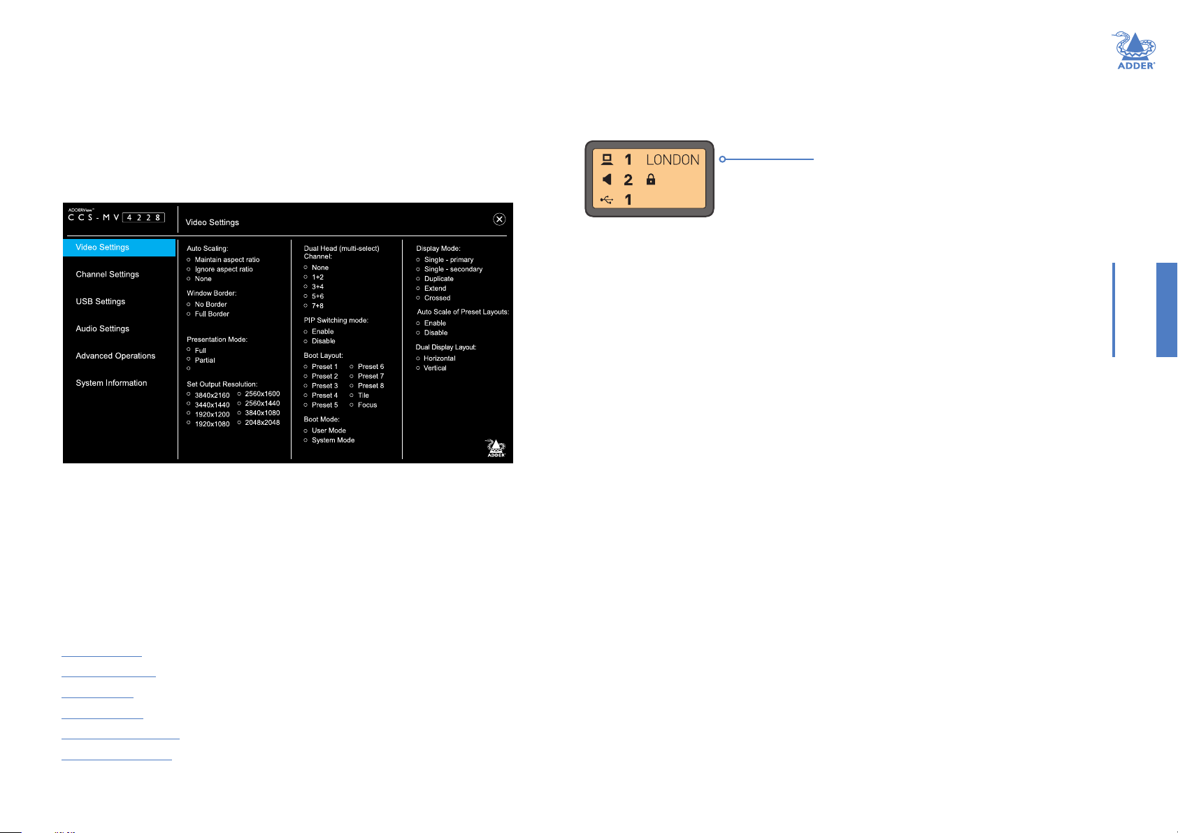
Channel names
The front panel display screen clearly shows the currently selected channel number(s)
for the video, audio and USB connections. In addition, you can optionally choose to show
a channel name:
Currently selected channel number(s)
supplying the video, audio and USB connections
Notes:
• The padlock symbol next to audio indicates
that Audio Hold has been applied to the
displayed channel.
• If the selected channel is connected to a dual
head PC (see page 12), then a ‘+’ symbol
will be displayed next to the channel number,
eg CH: 1+ ADDER_01
To enter/edit a channel name
1 Access the OSD and select the Channel Settings page (see page 13).
2 Use the Channel Name option to enter the required name.
Changing channel indicator colors
On the front panel there is a numbered button for each channel. To assist with visual
feedback for the operator you can change the highlight color for each button that will
be shown as each channel is selected. The same color choice will also be used on the
optional remote control, when used as well as for each window border.
To enter/edit a channel color
1 Access the OSD and select the Channel Settings page (see page 13).
2 Use the Channel Color option to select the required color.
INSTALLATIONCONFIGURATIONOPERATION
FURTHER
INFORMATION
INDEX
11
Page 13

OSD - Video Settings
To get here
• On the console keyboard, enter the following in succession:
Left Ctrl then Left Ctrl then o (upper or lower case accepted)
Auto Scaling
Maintain aspect ratio - The channel video aspect ratio will be
maintained when the user resizes the window. This will result in a black
bar being displayed where the window aspect ratio differs.
Ignore aspect ratio - This mode is best when you wish to manipulate
display windows to ll blank space on the display canvas.
None - The channel video size and aspect ratio will remain the same
regardless of the window size.
Window Border
Denes whether a border is displayed for each channel window, or not.
If displayed then the color of the border is determined by the Channel
Color (see Channel Settings).
Presentation Mode
This mode relates to the behavior when switching using the front panel
buttons:
Full - When switching to a new channel from the front panel, it will be
displayed in full screen.
Partial - Tile and full-screen mode will be used alternately when
switching to a new channel will be used when switching to a new
channel.
Off - When switching to a new channel, the currently selected method
of presentation will be retained.
Set Output Resolution
Choose the required output screen resolution. If two displays are
connected, then the same resolution will be used for both.
IMPORTANT: Ensure that the display(s) support the desired output
resolution. If not, the display will go blank. To resolve, change the output
resolution using a hotkey: “L Ctrl | R Ctrl | D | # ”, where # is 1 to 8.
Dual Head (multi-select) Channel
Allows you to specify connection to 1 or 2 dual head PCs, rather than
the default single head PCs. The default ‘None’ setting means that the
input channels are treated as single head, but the channels 1+2 and 3+4
may be designated as dual heads. Please refer to page 10 for dual head
connections.
PIP Switching Mode
Picture in Picture mode. When enabled, the multi-viewer will switch to
a small window inset within a larger window. When disabled, the mouse
instead passes behind the inset window.
Boot Layout
Determines which preset layout should be loaded at each power on
boot.
Boot Mode
In User mode you are interacting with the host computer, whereas in
System mode you are interacting directly with the multi-viewer switch,
for tasks such as moving or resizing windows.
Display Mode
Single - primary - Video is only output to video port #1. This option
should be used if only connecting a single display.
Single - secondary - Video is only output on video port #2. This option
would be used if, say sharing a second display between 2 multi-viewers.
Duplicate - The secondary display is a duplicate of the primary.
Extend - The display extends across both the primary and secondary
displays. You can move windows between displays and dene presets that
utilize the extended desktop.
Crossed - Similar to Extend, except that the primary and secondary
displays are reversed. To uncross, select Extend mode.
Auto Scale of Preset Layouts
When enabled, the preset layouts will ll the screen; if necessary, ignoring
the aspect ratio. When disabled, the layout will respect the Auto Scaling
setting.
Dual Display Layout
Denes how your video displays are arranged:
Horizontal - The displays positioned side by side.
Vertical - The displays are arranged top and bottom.
INSTALLATIONCONFIGURATIONOPERATION
FURTHER
INFORMATION
INDEX
12
Page 14

OSD - Channel Settings
To get here
1 On the console keyboard, enter the following in succession:
Left Ctrl then Left Ctrl then o (upper or lower case accepted)
2 Click the Channel Settings menu item.
INSTALLATIONCONFIGURATIONOPERATION
Channel Name
Allows you to add a name for each channel. To do so: Select a channel
number in the upper section, enter the name in the Channel Name eld
(up to 8 characters) and press Return.
Visibility
By default, a window is unpinned, which means it may be located on
top or behind other windows, as they are moved across the display.
Alternatively, the window may be pinned to the top or sent to the back.
Channel Color
On the front panel there is a numbered button for each channel. To assist
with visual feedback for the operator you can change the highlight color
for each button and window border color that will be shown as each
channel is selected.
FURTHER
INFORMATION
INDEX
13
Page 15

OSD - USB Settings
To get here
1 On the console keyboard, enter the following in succession:
Left Ctrl then Left Ctrl then o (upper or lower case accepted)
2 Click the USB Settings menu item.
INSTALLATIONCONFIGURATIONOPERATION
Mouse Parking
Refers to hiding the mouse when the user moves to the other monitor.
CTRL Key
Allows you to choose which Ctrl button on the keyboard that will be
used as a hotkey.
Device Emulator Interfaces
Species the user interface peripheral capabilities that are communicated
to the host PC.
Note: Consumer Report is a type of keyboard. Some versions of Linux do not
support Absolute Mouse mode.
Note: Mac keyboards aren’t supported, although the user may connect to a
Mac host PC.
Keyboard Hotkeys
Determines whether keyboard hotkeys can be used.
Keyboard Shortcuts
Reserved for future use.
Mouse Mode
Denes the behavior of the multi-viewer system. Absolute mode is
recommended for most users. Relative mode will disable mouse-based
switching; leaving the front panel or hotkeys as the available switching
methods.
Note: Ensure that whichever Mouse Mode is selected, the corresponding Device
Emulator setting is also enabled.
External API
Determines whether external API routines can be used.
Mouse Switching
Determines which of the extra buttons of specially-equipped mouse
devices can be used to switch channels.
FURTHER
INFORMATION
INDEX
14
Page 16

OSD - Audio Settings
To get here
1 On the console keyboard, enter the following in succession:
Left Ctrl then Left Ctrl then o (upper or lower case accepted)
2 Click the Audio Settings menu item.
INSTALLATIONCONFIGURATIONOPERATION
Audio Mixing
It refers to output only and only applies to digital audio from the HDMI
port.
Note: Analog audio is always to single channel; either selected or on-hold.
The front panel audio Hold button only applies to analog audio.
FURTHER
INFORMATION
INDEX
15
Page 17

OSD - Advanced Operation
To get here
1 On the console keyboard, enter the following in succession:
Left Ctrl then Left Ctrl then o (upper or lower case accepted)
2 Click the Advanced Operation menu item.
INSTALLATIONCONFIGURATIONOPERATION
Reset to Factory Defaults
Removes all user entered conguration details. This operation cannot be
undone.
Note: To avoid accidental resets, press and hold (for roughly 4 seconds).
Reset Device
Effectively reboots the multi-viewer.
Note: To avoid accidental resets, press and hold (for roughly 4 seconds).
System Upgrade / 2x Video Upgrades
Initiate either System or Video FPGA rmware upgrades. The label will
blink whilst the upgrade is in progress. See page 20 for a description of
the upgrade procedure.
FURTHER
INFORMATION
INDEX
16
Page 18

OSD - System Information
To get here
1 On the console keyboard, enter the following in succession:
Left Ctrl then Left Ctrl then o (upper or lower case accepted)
2 Click the System Information menu item.
INSTALLATIONCONFIGURATIONOPERATION
This page is intended to aid technical support. It displays the version
number for the System and Video Controllers, plus Front Panel rmware.
It also displays the Video FPGA version and System Type: (Secured or
Commercial).
FURTHER
INFORMATION
INDEX
17
Page 19

COPY & PASTE
The optional Copy & Paste function enables seamless, high-speed copying of les and
text from one Windows 10 computer to another. For details about using this feature,
please see page 25.
There are two ways to use the Copy & Paste function:
Mode 1: Using the internal COM Device - used for transferring only text, up to 1,000
characters and requires no external storage device.
Mode 2: Using an external USB Device - can transfer les as well as text.
To use either of these options, you rst need to download and install a small driver le
onto all computers that are required to use the Copy & Paste function. You then need to
enable the required mode: COM Device (see right) or USB Device (see page 19).
Installing the Copy & Paste driver
This stage needs to be carried out regardless of the chosen mode.
To install the driver
1 Connect the computers and user peripherals to the various ports of the multi-viewer
switch, as discussed earlier in this chapter.
Note: Ensure all devices and computers are connected prior to powering the multi-viewer
switch on. Some devices, such as user displays, are not recognized if connected after the
switch is already powered on.
2 Download the Copy & Paste driver le from the Adder website:
www.adder.com
3 Install the driver le separately onto each computer that will use the Copy & Paste
function. Once the software has been installed successfully, a software shortcut will
appear on the desktop and a setup icon will appears on the taskbar of each computer.
4 You now need to enable the required Copy & Paste option:
• COM device uses the multi-viewer COMputer on-board memory (see right).
• USB device uses an external USB memory device (ash drive) for copying larger
amounts of data - see page 19.
Enabling the COM Device mode
(If you wish to enable the USB Device mode, see the next page.)
This mode allows you to copy & paste up to 1,000 plain text characters using the
switch’s memory for storage. It is designed to support the quick transfer of short text
information between sources, such as telephone numbers, emails, web links, etc.
To enable the COM Device mode
1 Carry out these steps once on just one of the host computers:
a Open the Notepad app (or any other text editor) and press:
Left Ctrl then Right Ctrl then t (upper or lower case is accepted)
b Ignore the menu text that appears and press:
Left Ctrl then Right Ctrl then x
c Close the Notepad app.
2 Carry out these steps on ever y computer that will use the Copy & Paste function:
a Press: Left Ctrl then Right Ctrl then q
b From the taskbar on the desktop, locate the setup icon, and right-click on it to open
the menu below:
c Click Settings and in the window that opens, click Show advanced settings.
d From the additional tabs that open, choose the COM Device tab.
e In the window that opens, tick the Use COM Device checkbox and click OK.
INSTALLATIONCONFIGURATIONOPERATION
FURTHER
INFORMATION
18
INDEX
Page 20

Enabling the USB Device mode
This mode allows you to copy & paste text and les using an external USB storage
device as the temporary memory. Each host computer must have a USB link between it
and the switch.
To enable the USB Device mode
1 Connect an external FAT32-formatted USB storage device to one of the USB 3.0
Console ports on the rear panel of the switch. This USB storage device should appear
on the computer’s drivers list.
2 On every computer that will use the Copy & Paste function:
a On the taskbar, locate the setup icon and right-click on it to open the menu below:
INSTALLATIONCONFIGURATIONOPERATION
b Click the Settings option and then click Show advanced settings.
c Click the USB Device tab.
d Select the Use USB Device checkbox.
e From the Select from device list, select the USB storage device.
f Click OK.
FURTHER
INFORMATION
INDEX
19
Page 21

CCS-MV UPGRADE PROCESS
1 Download and install Adder CCS-MV Firmware Upgrade tool from Adder.com on a
PC not connected to the multi-viewer switch.
2 Power up the multi-viewer and open the OSD (Left Ctrl | Right Ctrl | O).
a For System Firmware upgrade select “Advanced operations” -> “System Upgrade”.
b For Video Firmware upgrade select “Advanced operations” -> “Video Upgrade”.
Note: Both video 1 and 2 should be upgraded together.
3 An “Upgrade” message will be displayed on the unit’s front panel. The selected option
is shown as blinking on the OSD.
Note: Only one rmware may be upgraded at a time. Repeat the process if both
upgrades are required.
4 Connect a USB A to A cable from the PC to the unit’s upper K/M port.
Troubleshooting
Issue Remedy
“STM Device in DFU mode” does not
appear.
System upgrade incomplete. 1 Disconnect the USB A to A cable.
Video FPGA upgrade incomplete. 1 Disconnect the USB A to A cable.
FW doesn’t initiate properly.
Error code 0xC000007B or
“mfc140.dll missing” message.
1 Check the driver installation under C:\
Program Files (x86)\Adder Technology\Firmware
Upgrade Tool\Drive\x86
2 Install the driver: STtube30.sys manually.
3 “STM Device in DFU Mode” should now
reported under serial bus controllers in
Device Manager.
2 Power cycle the unit, whilst at the same
time depress the channel 1 and channel 4
buttons simultaneously on the front panel.
3 The unit will enter upgrade mode, whereby
an “Upgrade” message is displayed on the
front panel.
4 Repeat the upgrade process from step #4.
2 Enter the hotkey Left Ctrl Right Ctrl Ins 2.
3 The unit will enter upgrade mode, whereby
an “Upgrade” message is displayed on the
front panel.
4 Repeat the upgrade process from step #4.
Download and install Microsoft Visual C++
Redistributable 2015-2019 (x86), which can be
found at: https://docs.microsoft.com/en-us/cpp/
windows/latest-supported-vc-redist?view=msvc-170
INSTALLATIONCONFIGURATIONOPERATION
5 Open the Upgrade Tool and congure as follows:
a Select “STM Device in DFU mode” under “Available DFU Devices”.
b Within the “Upgrade or Verify Action” section press “Choose…” to select the
rmware le.
c Select “Upgrade” to initiate the process. The progress bar will then indicate progress.
6 Wait for the upgrade process to be completed, whereupon a “Verify complete”
message will appear on the progress bar.
7 Disconnect the USB A to A cable and power cycle the unit.
8 For each rmware le to be upgraded, repeat steps 2 to 7.
FURTHER
INFORMATION
INDEX
20
Page 22

Operation
The multi-viewer switch allows the user to view the video outputs of up to eight host
computers simultaneously, either on a single display or dual displays. Keyboard and mouse
control is assigned to a single host computer at a time and is switchable using a number
of methods (see page 23).
Hold
USB
audio
Channel buttonsHold
Status display
Audio Hold
The Audio Hold button prevents switching the audio port when changing
the other console peripherals (keyboard, mouse, video) to another
computer channel. This function is useful when you need to listen to the
audio from one computer while working on another.
Using the front panel computer channel buttons, rst connect the console peripherals
to the computer from where the audio feed is required. Press the Audio Hold button on
the front panel. Then press the channel button for the computer that is required for the
other peripherals. The audio association will be signalled by the right indicator on each
channel’s front panel push button.
To release the audio from hold status, press the Audio Hold button again.
USB Hold
The USB Hold button prevents switching the Hi-Speed USB port when
changing the other console peripherals (keyboard, mouse, video, audio) to
another computer channel. This button functions in the same manner as the
Audio Hold button described above.
Status display
The status display shows which channel numbers are currently
selected to provide the video, audio and Hi-Speed USB
connections.
INSTALLATIONCONFIGURATIONOPERATION
21
FURTHER
INFORMATION
INDEX
Page 23

DISPLAYING WINDOWS
You can choose how to view the windows of the various host computers.
Full screen
Shows a single window on the whole screen.
• On the keyboard, press and release: L Ctrl | L Ctrl | f
Note: This means press and release the following keys:
Left Ctrl then Left Ctrl then f
For dual displays, it applies to the screen with cursor focus.
Tile layout
Shows eight windows on the display in a 3x3 grid.
• On the keyboard, press and release: L Ctrl | L Ctrl | q
Focus layout
One window is shown at a larger size with the other windows
scaled down and located on the right-hand side of the screen.
• Press: L Ctrl | L Ctrl | s
Select System mode and then rotate the mouse thumbwheel to
move the focus between the windows. If thumbwheel switching
is disabled (see USB Settings page 14), then either select focus
channel from front panel or window within System mode.
Alternatively, select a window in System mode to make that the focus window.
1
Custom layouts
If custom layouts have been saved (see page 24), you can select one as follows:
• Press: L Ctrl | L Ctrl | F# (where F# is the required function key: F1 to F8)
Dual displays
When dual displays are used in
Extend Display Mode (page 12),
the secondary display will remain
blank until you drag a window on it
or select a preset layout that uses it.
The Tile layout displays 4 windows
on each display.
The Focus layout is recommended for
dual displays, as per the diagram to the
right.
INSTALLATIONCONFIGURATIONOPERATION
22
FURTHER
INFORMATION
INDEX
Page 24

SWITCHING BETWEEN CHANNELS
12
34
• Press the required channel button on the front panel:
Hold
audio
USB
• In any of the multi-view layouts, simply move the mouse cursor across the boundaries
of the display windows*.
* The mouse method relies on absolute mouse mode, which can be enabled and disabled by the
user to match their own preferences and to ensure compatibility with their computers.
To use absolute mouse mode, press: L Ctrl | L Ctrl | F11 | c
To use relative mouse mode, press: L Ctrl | L Ctrl | F11 | b
In Relative mouse mode, channel switching is restricted to either the front panel buttons or the
scrolling the mouse thumbwheel.
Channel buttonsHold
Status display
MANAGING WINDOWS
In everyday use, the multi-viewer switch has two main modes of operation:
• User mode - this is the normal mode of operation, where the switch is essentially
transparent. This means that your commands pass straight through to interact with the
host PC(s), as if you were directly connected to them.
• System mode - in this mode, your link with the PC(s) is temporarily suspended and
instead you interact directly with the switch. This allows you to perform certain tasks,
such as resizing windows and arranging preset layouts.
It is quick and easy to change between the two modes, as follows.
Entering and exiting system mode
To enter system mode
• On the keyboard, press and release the following: Left Ctrl then Left Ctrl then o
Note: In the pages that follow, such sequences are shown in the form: L Ctrl | L Ctrl | o
or
• On the mouse, either click the scroll wheel, or for a ve-button mouse, select either
of the side buttons. Note: The mouse must be set to use Absolute Mode (see page 14) .
Within system mode you will see a large blue cursor; in this mode keyboard strokes and
mouse movements are not transmitted to the computers, but instead are interpreted
within the multi-viewer switch.
To return to user mode
• Press L Ctrl | L Ctrl | u to return to user mode.
or
• On the mouse, either click the scroll wheel, or for a ve-button mouse, select either
of the side buttons.
Taking control of a window
1 In a multi-window layout, enter System Mode, as described above.
2 Move the large blue cursor to the window that you wish to take control.
3 Now, either:
• Take control of the chosen window at the current size: Click the scroll wheel.
or
• Maximise and take control of the chosen window: Double click the left mouse
button.
In either case, you will revert to user mode with control of the selected computer.
INSTALLATIONCONFIGURATIONOPERATION
FURTHER
INFORMATION
INDEX
23
Page 25

Custom Preset Layouts
In system mode, the mouse cursor is also responsible for re-sizing and moving windows
around within the display canvas. It is advisable to begin with one of the predened
layouts and adjust it to suit your requirements. These layouts can be selected before or
after entering system mode:
• For tile layout, use the hotkey combination: L Ctrl | L Ctrl | q
• For focus layout, use the hotkey combination: L Ctrl | L Ctrl | s
• For a custom layout, use the hotkey combination: L Ctrl | L Ctrl | F#
(where F# is the required function key: F1 to F8)
Manipulate the windows to the desired sizes and locations, then apply the new layout to
a function key: L Ctrl | L Ctrl | F11 | Ins | F#
(where F# is the required function key: F1 to F8).
Once you have exited system mode, you will be able to switch between the predened
tile and focus layouts as well as recall your own custom presets.
Resizing and moving windows
There are a number of options available when resizing windows, including the options to
retain the aspect ratio or select only a partial element of the computer’s display.
To use autoscaling
The autoscaling feature allows selected windows to ll the screen, either respecting or
overriding the aspect ratio, depending on the selected option. Autoscaling can be enabled
either through the OSD menu or by using the following hotkey combinations:
• To enable autoscaling with aspect ratio maintained: L Ctrl | L Ctrl | F11 | w | w
• To enable autoscaling without aspect ratio being maintained: L Ctrl | L Ctrl | F11| w | y
• To disable autoscaling: L Ctrl | L Ctrl | F11 | w | n
With your preferred scaling option selected, windows can now be manipulated using the
blue mouse cursor.
To move a window
Locate the blue mouse cursor anywhere within the window. Press and hold the left mouse
button and drag the window to your desired location. Release the left mouse button.
To resize a window
Place the blue mouse cursor at the lower-right corner of the required window. Press
and hold the right mouse button and drag to resize the window up or down accordingly.
Release the right mouse key when the window is at the desired size.
Depending on the current autoscaling setting, the video will (or won’t) adjust in size and/
or aspect ratio. To force the source to rescale within the dened window you can use
either of the following:
• To ll with a xed aspect ratio: L Ctrl | L Ctrl | F11 | w
• To ll with a non-xed aspect ratio: L Ctrl | L Ctrl | F11 | y
INSTALLATIONCONFIGURATIONOPERATION
24
FURTHER
INFORMATION
INDEX
Page 26

USING COPY & PASTE
The optional Copy & Paste function allows you to copy text and les from one host PC
to another.
There are two ways to use the Copy & Paste function:
Mode 1: Using the internal COM Device - used for transferring only text, up to 1,000
characters and requires no external storage device.
Mode 2: Using an external USB Device - can transfer les as well as text.
Initial conguration
To use the Copy & Paste function, you will rst need to download and install a small
driver le onto all computers that are required to use the function. You will also need to
choose which mode you wish to use. Please see page 18 for details.
Using the COM Device mode
Allows you to Copy & Paste up to 1,000 plain text characters using the switch’s memory
for storage. It is designed to support the quick transfer of short text information
between sources, such as telephone numbers, emails, web links, etc.
To use the COM Device mode
1 On the source computer, highlight the text (up to 1,000 characters) and perform a
standard copy function using the mouse or keyboard. The copied text is stored within
the switch’s local memory.
2 Switch to the target computer and perform a standard paste function to the desired
location. The text is copied as plain text, with no formatting parameters.
Note: A small pop-up window on the taskbar provides status updates once text is copied or
available for paste on a specic computer. The last copied data will remain stored in memory,
until any other copy function is performed. This allows you to paste the same text on several
computers.
INSTALLATIONCONFIGURATIONOPERATION
Using the USB Device Mode
The USB Device mode uses an external USB storage device to store copied data and
allows you to copy & paste both text and les from one computer to another (up to
999Mb). It is designed to support large text and le copying between sources.
To use the USB Device mode
1 On the source computer, highlight the desired text or choose a le and perform a
standard copy function using the mouse or keyboard. The copied data is stored on the
external USB storage device.
2 Switch to the target computer and perform a standard paste function via the mouse
or keyboard to the desired location.
The last copied data will be retained within the USB storage device (until such time as
it is replaced by another copy action) so that you can paste pasting the same data on
several computers.
Note: When moving to a specic computer, the “USB External Storage Auto-run” pop-up
message will appear. It is possible to disable this in the conguration options.
FURTHER
INFORMATION
25
INDEX
Page 27

Further information
This chapter contains a variety of information, including the following:
• Getting assistance - see right
• Appendix A - Hotkey commands
• Appendix B - Open Source Licenses
GETTING ASSISTANCE
If you are still experiencing problems after checking the information contained within this
guide, then please refer to the Support section of our website:
www.adder.com
INSTALLATIONCONFIGURATIONOPERATION
FURTHER
26
INFORMATION
INDEX
Page 28

APPENDIX A - Hotkey commands
This section provides a summary of hotkey commands used on the multi-viewer switch.
Note: The hotkeys assume the use of a US keyboard.
To invoke the OSD
Press and release Left Ctrl then Right Ctrl then o
To invoke the video FPGA upgrade mode
Press and release: Left Ctrl then Right Ctrl then INS 2
Other commands
Press and release: Left Ctrl then Left Ctrl then:
User mode u
Maximize window to full-screen f
Tile window layout (quad view) q
Focus window layout s
Select channel # (where # is 1 to 8)
Increase window scaling +
Reduce window scaling -
Set output display resolution F11 d# (where # is 1 to 8)
• 1 = 2048 x 2048
• 2 = 2560 x 1440
• 3 = 2560 x 1600
• 4 = 1920 x 1080
• 5 = 1920 x 1200
• 6 = 3840 x 1080
• 7 = 3440 x 1440
• 8 = 3840 x 2160
Unpin all windows F11 f r
Pin/unpin window toggle F11 F#
(where # is the required function key: F1 to F8)
PiP mode toggle F11 INS p
Load presets 1..8 F1..F8
Save preset 1..8 F11 INS F1..F8
Relative mouse mode F11 b
Absolute mouse mode F11 c
Presentation mode off F11 n
Presentation mode on F11 p
Reset to factory defaults F11 r
Reboot unit F11 INS r
Fix aspect ratio F11 w
Non-xed aspect ratio F11 y
Enable autoscaling with aspect ratio maintained F11 w w
Enable autoscaling without aspect ratio maintained F11 w y
Disable autoscaling F11 w n
Increase mouse speed F11 +
Reduce mouse speed F11 -
Move and resize window F11 End <Channel> <Operation> <Percent>
Refer to the API Manual (MAN-0000023) for further details
INSTALLATIONCONFIGURATIONOPERATION
FURTHER
INFORMATION
27
INDEX
Page 29

APPENDIX B – OPEN SOURCE LICENSES
This product includes binaries that are derived from the open source community.
STMicroelectronics SLA0048 - Rev 4 (March 2018)
Under STMicroelectronics’ intellectual property rights and subject to applicable licensing
terms for any third-party software incorporated in this software package and applicable
Open Source Terms (as dened here below), the redistribution, reproduction and use in
source and binary forms of the software package or any part thereof, with or without
modication, are permitted provided that the following conditions are met:
1 Redistribution of source code (modied or not) must retain any copyright notice, this
list of conditions and the following disclaimer.
2 Redistributions in binary form, except as embedded into microcontroller or
microprocessor device manufactured by or for STMicroelectronics or a software
update for such device, must reproduce the above copyright notice, this list of
conditions and the following disclaimer in the documentation and/or other materials
provided with the distribution.
3 Neither the name of STMicroelectronics nor the names of other contributors to this
software package may be used to endorse or promote products derived from this
software package or part thereof without specic written permission.
4 This software package or any part thereof, including modications and/or derivative
works of this software package, must be used and execute solely and exclusively on or
in combination with a microcontroller or a microprocessor devices manufactured by
or for STMicroelectronics.
5 No use, reproduction or redistribution of this software package partially or totally may
be done in any manner that would subject this software package to any Open Source
Terms (as dened below).
6 Some portion of the software package may contain software subject to Open Source
Terms (as dened below) applicable for each such portion (“Open Source Software”),
as further specied in the software package. Such Open Source Software is supplied
under the applicable Open Source Terms and is not subject to the terms and
conditions of license hereunder.
“Open Source Terms” shall mean any open source license which requires as part of
distribution of software that the source code of such software is distributed therewith
or otherwise made available, or open source license that substantially complies
with the Open Source denition specied at www.opensource.org and any other
comparable open source license such as for example GNU General Public License
(GPL), Eclipse Public License (EPL), Apache Software License, BSD license and MIT
license.
7 This software package may also include third party software as expressly specied in
the software package subject to specic license terms from such third parties. Such
third party software is supplied under such specic license terms and is not subject
to the terms and conditions of license hereunder. By installing copying, downloading,
accessing or otherwise using this software package, the recipient agrees to be bound
by such license terms with regard to such third party software.
8 STMicroelectronics has no obligation to provide any maintenance, support or updates
for the software package.
9 The software package is and will remain the exclusive property of STMicroelectronics
and its licensors. The recipient will not take any action that jeopardizes
STMicroelectronics and its licensors’ proprietary rights or acquire any rights in the
software package, except the limited rights specied hereunder.
10 The recipient shall comply with all applicable laws and regulations affecting the use of
the software package or any part thereof including any applicable export control law
or regulation.
11 Redistribution and use of this software package partially or any part thereof other
than as permitted under this license is void and will automatically terminate your
rights under this license.
THIS SOFTWARE PACKAGE IS PROVIDED BY STMICROELECTRONICS AND
CONTRIBUTORS “AS IS” AND ANY EXPRESS, IMPLIED OR STATUTORY
WARRANTIES, INCLUDING, BUT NOT LIMITED TO, THE IMPLIED WARRANTIES
OF MERCHANTABILITY, FITNESS FOR A PARTICULAR PURPOSE AND NONINFRINGEMENT OF THIRD PARTY INTELLECTUAL PROPERTY RIGHTS ARE
DISCLAIMED TO THE FULLEST EXTENT PERMITTED BY LAW. IN NO EVENT
SHALL STMICROELECTRONICS OR CONTRIBUTORS BE LIABLE FOR ANY DIRECT,
INDIRECT, INCIDENTAL, SPECIAL, EXEMPLARY, OR CONSEQUENTIAL DAMAGES
(INCLUDING, BUT NOT LIMITED TO, PROCUREMENT OF SUBSTITUTE GOODS
OR SERVICES; LOSS OF USE, DATA, OR PROFITS; OR BUSINESS INTERRUPTION)
HOWEVER CAUSED AND ON ANY THEORY OF LIABILITY, WHETHER IN
CONTRACT, STRICT LIABILITY, OR TORT (INCLUDING NEGLIGENCE OR
OTHERWISE) ARISING IN ANY WAY OUT OF THE USE OF THIS SOFTWARE
PACKAGE, EVEN IF ADVISED OF THE POSSIBILITY OF SUCH DAMAGE.
EXCEPT AS EXPRESSLY PERMITTED HEREUNDER AND SUBJECT TO THE
APPLICABLE LICENSING TERMS FOR ANY THIRD-PARTY SOFTWARE
INCORPORATED IN THE SOFTWARE PACKAGE AND OPEN SOURCE TERMS AS
APPLICABLE, NO LICENSE OR OTHER RIGHTS, WHETHER EXPRESS OR IMPLIED,
ARE GRANTED UNDER ANY PATENT OR OTHER INTELLECTUAL PROPERTY
RIGHTS OF STMICROELECTRONICS OR ANY THIRD PARTY.
INSTALLATIONCONFIGURATIONOPERATION
FURTHER
INFORMATION
INDEX
28
Page 30

www.adder.com
INSTALLATIONCONFIGURATIONOPERATION
FURTHER
INFORMATION
Documentation by:
www.ctxd.com
INDEX
© 2023 Adder Technology Limited
All trademarks are acknowledged.
Part No. MAN-000032 • Release 1.0
29
Page 31

Index
A
Advanced Settings 16
Audio Hold 21
Audio Settings 15
Autoscaling 24
C
Channel button
colors 11
Channel name 11
Channels
switching between 23
Channel Settings 13
Colors
button indicators 11
Connections 6
computer 7
console 8,9
overview 6
power 9
remote control unit 9
Copy & Paste
conguring 18
using 25
D
Displays
initial setup 10
F
Focus layout 22
H
Hotkeys 27
O
On Screen Display (OSD) 11
P
Ports 6
Power in 9
Preset layouts 24
Q
Quadrant.See Tile layout
S
Settings
audio 15
channel 13
USB 14
video 12
Software upgrade 20
Speakers 8
Specications 3
T
Technical specications 3
Tile layout 22
U
Upgrade 20
USB Settings 14
V
Video Settings 12
W
Window congurations 22
Windows
managing 23
resizing and moving 24
INSTALLATIONCONFIGURATIONOPERATION
FURTHER
30
INFORMATION
INDEX
 Loading...