

Page 1
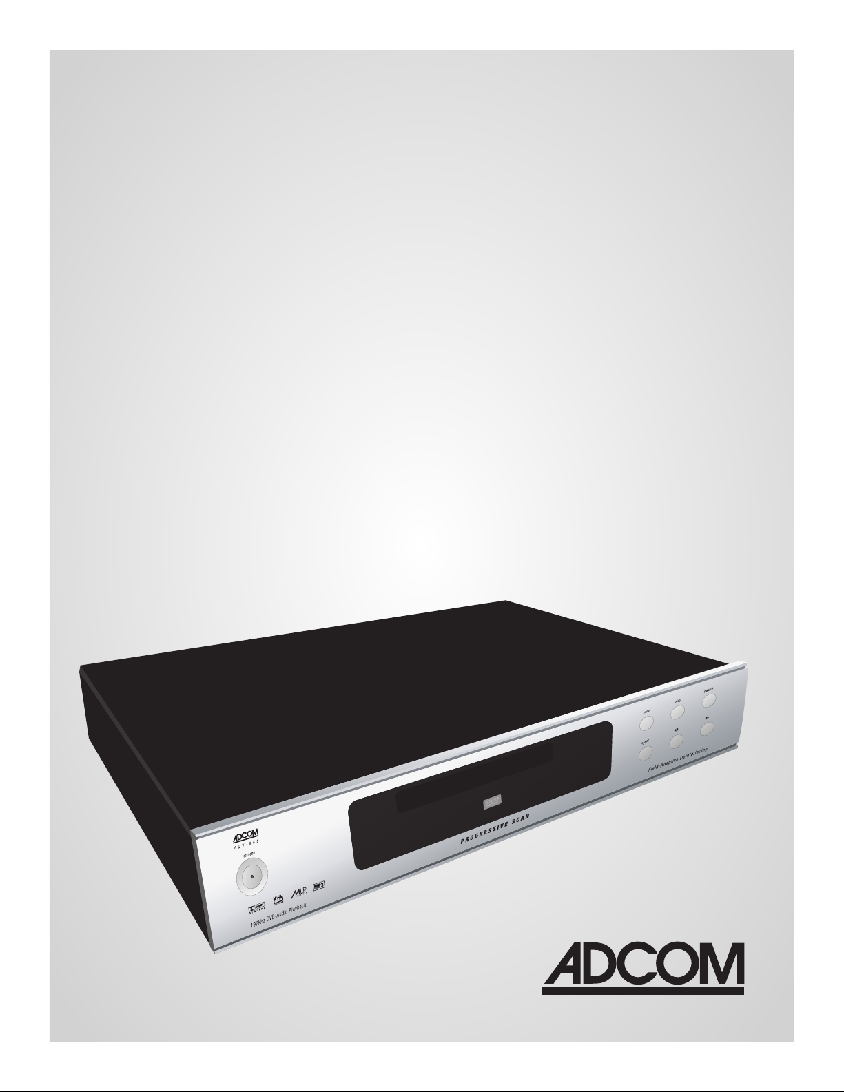
GDV-850
Progressive Scan
DVD-Audio/Video Player
1ADCOM GDV-850 Owner’s Manual |
Page 2

3ADCOM GDV-850 Owner’s Manual |
WELCOME
Dear Fellow ADCOM Product Owner,
Welcome to the ADCOM family! For more than twenty years, ADCOM products have delivered
excellent performance and value for customers around the world. Our products are designed by
our experienced and demanding engineering team, built to the highest standards in our factory,
and sold and serviced through dealers, custom installers, and other retailers whose primary goal
is your complete satisfaction.
We know you are anxious to see and hear your new DVD player in action, but please take a few
minutes to read this owner’s manual before connecting the DVD player to your system. It is
particularly important that you connect your DVD player to your preamplifier while the amplifier and preamplifier are unplugged and your other equipment is turned off. This will protect
your equipment from potential short circuits that may occur during installation. In addition, it is
important that you allow for adequate ventilation around your DVD player and other equipment,
since excessive heat buildup can shorten the life of any electronic product, including the DVD
player. Once you have correctly connected your new DVD player to your other components, you
should be able to enjoy many trouble-free years of performance.
We conduct a thorough quality and performance test on each and every DVD player we build in
our factory prior to shipment. In the rare case of a defect that may occur after shipment, we
stand behind our DVD players with a two-year parts and labor warranty. To register for this warranty, please complete and mail the enclosed warranty card back to ADCOM. Also, please keep
a copy of your sales receipt with the owner’s manual so you may provide proof of eligibility for
the warranty should the need arise.
We know you will be very happy with the audio and video performance of your new DVD player. We
hope you will also consider other ADCOM products, such as our line of multichannel amplifiers and
preamplifiers. In addition, we design and manufacture complementary products such as surge suppressors and speaker selectors. Please visit our web site at www.adcom.com to learn more about
our complete line of stereo, home theater, and distributed audio/video products.
On behalf of all of us at ADCOM, I want to thank you for selecting our product for your home or
business entertainment system.
Sincerely,
Douglas Klein
President
ADCOM is a registered trademark of Klein Technology Group, LLC.
ADCOM Telephone: (480) 607-2277
A division of Klein Technology Group, LLC Fax: (480) 348-9876
8541 East Anderson Drive Email: info@adcom.com
Scottsdale, Arizona 85255 USA Web: www.adcom.com
Copyright © 2003 Klein Technology Group, LLC. All rights reserved. No part of this manual may be reproduced or electronically transmitted without the express written consent of Klein Technology Group, LLC.
| ADCOM GDV-850 Owner’s Manual2
Page 3

TABLE OF CONTENTS
Welcome . . . . . . . . . . . . . . . . . . . . . . . . . . . . . . . . . . . . . . . . . . 2
Table of Contents . . . . . . . . . . . . . . . . . . . . . . . . . . . . . . . . . . 3
Precautions and Warnings . . . . . . . . . . . . . . . . . . . . . . . . . . . 4
Unpacking Your GDV-850 . . . . . . . . . . . . . . . . . . . . . . . . . . . . 5
Warranty Information . . . . . . . . . . . . . . . . . . . . . . . . . . . . . . . . 5
Safety Information . . . . . . . . . . . . . . . . . . . . . . . . . . . . . . . . . 5
Description of Unit
1.1 Front Panel Illustration . . . . . . . . . . . . . . . . . . . . . . . . . . 7
1.2 Interface Overview . . . . . . . . . . . . . . . . . . . . . . . . . . . . . . 7
1.3 Rear Panel Illustration . . . . . . . . . . . . . . . . . . . . . . . . . . . 8
1.4 Input & Output System Connections . . . . . . . . . . . . . 8-9
1.5 Connection Diagrams
(Typical DVD Video) . . . . . . . . . . . . . . . . . . . . . . . . . . . . . 10
(Multichannel DVD-Audio) . . . . . . . . . . . . . . . . . . . . . . . . 11
Remote Control
2.1 Remote Control Illustration . . . . . . . . . . . . . . . . . . . . . . 12
2.2 Overview of the GRC-815 . . . . . . . . . . . . . . . . . . . . 13-15
2.3 RS232 / IR Control . . . . . . . . . . . . . . . . . . . . . . . . . . 15-17
Interface
3.1 Front Panel Display Illustration . . . . . . . . . . . . . . . . . . 18
3.2 Display Overview . . . . . . . . . . . . . . . . . . . . . . . . . . . . . . . 18
3.3 Display Features . . . . . . . . . . . . . . . . . . . . . . . . . . . . . . . 18
3.4 OSD Overview . . . . . . . . . . . . . . . . . . . . . . . . . . . . . . . . . . 18
Setup
4.1 Setup Overview . . . . . . . . . . . . . . . . . . . . . . . . . . . . . . . . 19
4.2 General Setup . . . . . . . . . . . . . . . . . . . . . . . . . . . . . . . 19-20
4.3 Speaker Setup . . . . . . . . . . . . . . . . . . . . . . . . . . . . . . . 20-21
4.4 Audio Setup . . . . . . . . . . . . . . . . . . . . . . . . . . . . . . . . . . . . 22
4.5 Preferences . . . . . . . . . . . . . . . . . . . . . . . . . . . . . . . . . 22-23
4.6 MP3 and JPEG Files . . . . . . . . . . . . . . . . . . . . . . . . . . . . . 24
4.7 Equalizer Settings . . . . . . . . . . . . . . . . . . . . . . . . . . . . . . 25
5.1 Technology Overview . . . . . . . . . . . . . . . . . . . . . . . . . . . 26
5.2 Trouble Shooting . . . . . . . . . . . . . . . . . . . . . . . . . . . . . . 27
5.3 Resolving Problems . . . . . . . . . . . . . . . . . . . . . . . . . . . . 27
5.4 System Reset . . . . . . . . . . . . . . . . . . . . . . . . . . . . . . . . . . 27
5.5 Caring for your GDV-850 . . . . . . . . . . . . . . . . . . . . . . . . 28
6.0 Service Information . . . . . . . . . . . . . . . . . . . . . . . . . . 28-29
6.1 Warranty . . . . . . . . . . . . . . . . . . . . . . . . . . . . . . . . . . . 28-29
6.2 Your Responsibilites . . . . . . . . . . . . . . . . . . . . . . . . . . . . 29
7.0 Specifications . . . . . . . . . . . . . . . . . . . . . . . . . . . . . . . . . 30
3ADCOM GDV-850 Owner’s Manual |
Page 4
5ADCOM GDV-850 Owner’s Manual |
THE FOLLOWING PRECAUTIONS AND SAFETY INSTRUCTIONS
ARE REQUIREMENTS OF UL AND CSA SAFETY REGULATIONS
Warning: To reduce the risk of re or electric shock, do
not expose this unit to rain or moisture.
The graphic symbol of a lightning ash with an
arrow point within a triangle signies that there
is dangerous voltage within the unit and it poses
a hazard to anyone removing the cover to gain
access to the interior of the unit. Only qualied
service personnel should make any such attempt.
The graphic symbol of an exclamation point within
an equilateral triangle warns a user of the device
that it is necessary to refer to the instruction manual
and its warnings for proper operation of the unit.
Do not place this unit on an unstable cart, stand, tripod,
bracket, or table. The unit may fall, causing serious
injury to a child or adult, and serious damage to the
unit. Use only with a cart, stand, tripod, bracket, or
table recommended by the manufacturer or sold with
the unit. Any mounting of the device should follow the
manufacturer’s instructions, and should use a mounting
accessory recommended by the manufacturer.
Read all the safety and operating instructions before connecting or using
this unit.
Retain this notice and the owner’s manual for future reference.
All warnings on the unit and in its operating instructions should be adhered to.
All operating and use instructions should be followed.
Do not use this unit near water. For example, near a bathtub, washbowl,
kitchen sink, laundry tub, in a wet basement, or near a swimming pool.
POUR PREVENIR LES CHOCS ELECTRIQUES NE PAS UTILISER CETTE FICHE
ATTENTION
POLARISEE AVEC UN PROLONGATEUR, UNE PRISE CE COURANT OU UNE
AUTRE SORTIE CE COURANT, SAUF SI LES LAMES PEUVENT ETRE INSEREES
A FOND SANS EN LAISSER AUCUNE PARTIE A DECOUVERT.
CAUTION
TO PREVENT ELECTRIC SHOCK DO NOT USE THIS POLARIZED PLUG WITH
AN EXTENSION CORD, RECEPTACLE OR OTHER OUTLET UNLESS THE
BLADES CAN BE FULLY INSERTED TO PREVENT BLADE EXPOSURE.
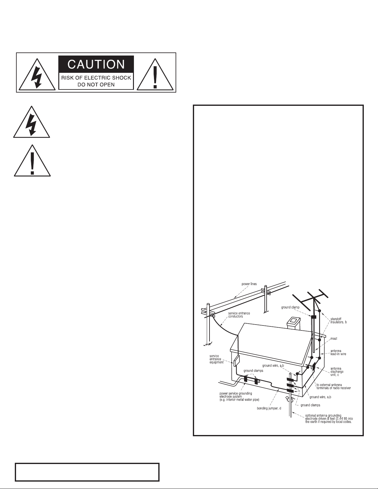
CAUTION POWER LINES
Any outdoor antenna must be located away from all power lines.
OUTDOOR ANTENNA GROUNDING
If an outside antenna is connected to your tuner or tuner/preamplier,
be sure the antenna system is grounded so as to provide some protection
against voltage surges and built-up static charges. Section 810 of the
National Electrical Code, ANSI/NFPA No. 701984, provides information
with respect to proper grounding of the mast and supporting structure,
grounding of the lead-in wire to an antenna discharge unit, size of
grounding conductors, location of antenna discharge unit, connection to
grounding electrodes, and requirements for the grounding electrode.
a. Use No.10 AWG (5.3 mm2) copper, No.8 AWG (8.4 mm2) aluminum, No.17
AWG (1.0 mm2) copper clad steel or bronze wire, or larger, as a ground wire.
b. Secure antenna lead-in and ground wires to house with stand-off
insulators spaced from 46 feet (1.221.83 m) apart.
c. Mount antenna discharge unit as close as possible to where lead-in enters
house.
d. Use jumper wire not smaller than No.6 AWG (13.3 mm2) copper, or the
equivalent, when a separate antenna grounding electrode is used. See NEC
Section 810-21 (j).
EXAMPLE OF ANTENNA GROUNDING AS PER NATIONAL ELECTRICAL CODE
INSTRUCTIONS CONTAINED IN ARTICLE 810. RADIO AND TELEVISION EQUIPMENT.
The unit should be installed so that its location or position does not interfere
with its proper ventilation. For example, it should not be situated on a
bed, sofa, rug, or similar surface that may block the ventilation openings;
or placed in a built-in installation, such as bookcase or cabinet, that may
impede the ow of air through its ventilation openings.
The unit should be situated away from heat sources such as radiators, heat
registers, stoves, or other devices (including ampliers) that produce heat.
The unit should be connected to a power supply outlet only of the voltage
and frequency marked on its rear panel.
The power supply cord should be routed so that it is not likely to be walked
on or pinched, especially near the plug, convenience receptacles, or where
the cord exits from the unit.
Clean unit only as recommended in its instruction manual.
The power supply cord of the unit should be unplugged from the wall outlet
when it is to be unused for a long period of time.
Care should be taken so that objects do not fall, and liquids are not spilled,
into the enclosure through any openings.
This unit should be serviced by qualied service personnel when:
A. The power cord or the plug has been damaged; or
B. Objects have fallen, or liquid has been spilled, into the unit; or
C. The unit has been exposed to rain, or liquids of any kind; or
D. The unit does not appear to operate normally, or exhibits a marked
change in performance; or
E. The device has been dropped, or the enclosure damaged.
DO NOT ATTEMPT SERVICING OF THIS UNIT YOURSELF.
| ADCOM GDV-850 Owner’s Manual4
REFER SERVICING TO QUALIFIED SERVICE PERSONNEL.
This reminder is provided to call the CATV system installer’s attention to
Article 82022 of the National Electrical Code that provides guidelines for
proper grounding and, in particular, species that the cable ground shall
be connected to the grounding system of the building, as close to the
point of cable entry as practical.
NOTE TO CATV SYSTEM INSTALLER
Page 5
Unpacking the GDV-850
Before your new ADCOM DVD player left
our factory, it was carefully inspected
for physical imperfections and tested
for all electrical parameters as a
routine part of ADCOM’s systematic
quality control. This, along with full
operational and mechanical testing,
should ensure a product awless in
both appearance and performance.
After you have unpacked the GDV-850,
inspect it for physical damage. Save
the shipping carton and all packing
material as they are intended to
reduce the possibility of transportation
damage should the DVD player ever
need to be shipped again. In the
unlikely event damage has occurred,
notify your dealer immediately and
request the name of the carrier so
a written claim to cover shipping
damages can be initiated. The right to
a claim against a public carrier can be
forfeited if the carrier is not notied
promptly in writing and if the shipping
carton and packing materials are not
available for inspection by the carrier.
Save all packing materials until the
claim has been settled.
Safety Instructions
DANGER: Visible and invisible laser
radiation when open and interlock
failed or defeated. Avoid direct
exposure to beam.
WARNING: There are no user
serviceable parts inside. Refer
all servicing to qualied service
personnel.
WARNING: To reduce the risk of re
or electric shock, do not expose the
unit to moisture or water. Do not
allow foreign objects to get into the
enclosure. If the unit is exposed to
moisture, or a foreign object gets into
the enclosure, immediately disconnect
the power cord from the wall. Take the
unit to a qualied service person for
inspection and necessary repairs. Read
all the instructions before connecting
or operating the component. Keep
this manual so you can refer to these
safety instructions. Heed all warnings
and safety information in these
instructions and on the product itself.
Follow all operating instructions. Clean
the enclosure only with a dry cloth or a
vacuum cleaner. You must allow 10 cm
or 4 inches of unobstructed clearance
around the unit. Do not place the unit
on a bed, sofa, rug, or similar surface
that could block the ventilation
openings. If the unit is placed in a
bookcase or cabinet, there must be
ventilation of the cabinet to allow
proper cooling. Keep the component
away from radiators, heat registers,
stoves, or any other appliance that
produces heat.
The unit must be connected to a power
supply only of the type and voltage
specied on the rear panel. Connect
the component to the power outlet
only with the supplied power supply
cable or an exact equivalent. Do not
modify the supplied cable. Do not
defeat grounding and/or polarization
provisions. The cable should be
connected to a 3-pin polarized wall
outlet, matching the wide blade of the
plug to the wide slot of the receptacle.
Do not use extension cords. Do not
route the power cord where it will
be crushed, pinched, bent, exposed
to heat, or damaged in any way. Pay
particular attention to the power cord
at the plug and where it exits the back
of the unit. The power cord should be
unplugged from the wall outlet if the
unit is to be left unused for a long
period of time. Immediately stop using
the component and have it inspected
and/or serviced by a qualied service
agency if:
• the power supply cord or plug has
been damaged;
• objects have fallen or liquid has
been spilled into the unit;
• the unit has been exposed to rain;
• the unit shows signs of improper
operation; or
• the unit has been dropped or
damaged in any way.
FCC Information: This equipment
has been tested and found to comply
with the limits for a Class B digital
device, pursuant to Part 15 of the
FCC Rules. These limits are designed
to provide reasonable protection
against harmful interference in
a residential installation. This
equipment generates, uses and
can radiate radio frequency energy
and, if not installed and used in
accordance with the instruction, may
cause harmful interference to radio
communications. However, there is
no guarantee that interference will
not occur in a particular installation.
If this equipment does cause harmful
interference to radio or television
reception, which can be determined
by turning the equipment off and
on, the user is encouraged to try to
correct the interference by one or
more of the following measures:
• Reorient or relocate the receiving
antenna.(TV, radio, etc.)
• Increase the separation between
the equipment and receiver
• Connect the equipment to an outlet
on circuit different from that to
which the receiver is connected.
• Consult the dealer or an
experienced radio/TV technician
for additional help.
Caution: This device complies with
part 15 of the FCC Rules operation is
subject to the following to conditions:
(1) This device may not cause harmful
interference, and (2) this device must
accept any interference received,
including interference that may cause
undesired operation.
5ADCOM GDV-850 Owner’s Manual |
Page 6
7ADCOM GDV-850 Owner’s Manual |
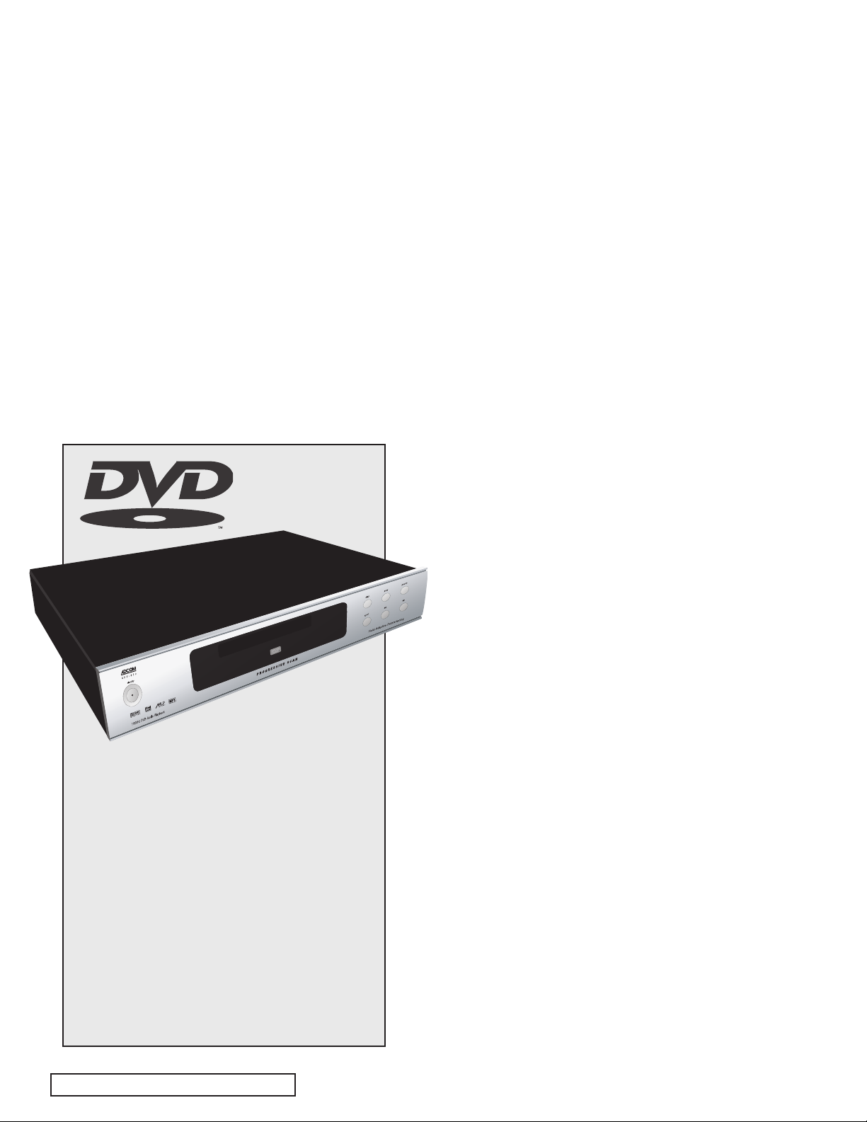
Description of Unit
Congratulations on your decision to purchase the ADCOM
GDV-850 DVD player. The GDV-850 delivers progressive scan
480p video output with field-adaptive deinterlacing via com-
ponent video connections. Direct multichannel analog out-
puts connect you to high-resolution stereo and multichannel
playback for your DVD-Audio material. The front panel of the
GDV-850 is designed for ease of operation. All controls are
logically grouped for intuitive operation. Basic operations
can be performed from the front panel, while additional
features can be accessed with the provided GRC-815 remote
control. Familiarize yourself with the diagrams that follow
and read the short explanations of each feature below. When
you finish, you will be well on your way to enjoying the GDV-
850’s convenience, performance, and quality.
Video Features
• Compatible with NTSC and PAL video hardware plus
standard (4:3) and wide-screen (16:9) aspect ratios.
• Progressive scan with reverse 3:2 pulldown for
film sources.
• Special playback functions such as frame-by-frame,
zoom, and variable slow-motion and high-speed play.
• DVD-Video features include multi-angle, multi-language
subtitles, and multi-language audio.
Audio Features
• Supports the following digital audio formats:
Dolby Digital®
DTS® (Digital Theater Systems)
DTS® 96/24
DVD-Audio
Manufactured under license from Dolby Laboratories. “Dolby”,
“Pro Logic”, “MLP Lossless”, and the double-D symbol are trade-
marks of Dolby Laboratories.
Manufactured under license from Digital Theater System, Inc.
US Pat. No. 5,451,942 and other world-wide patents issued and
pending. “DTS”, “DTS Digital Surround”, are trademarks of
Digital Theater Systems, Inc.”
This product incorporates copyright protection technology that
is protected by method claims of certain U.S. patents and other
intellectual property rights owned by Macrovision Corporation
and other rights owners. Use of this copyright protection tech-
nology must be authorized by Macrovision Corporation, and is
intended for home and other limited viewing uses only unless
otherwise authorized by Macrovision Corporation. Reverse engi-
neering or disassembly is prohibited.
MLP® (Meridian Lossless Packing)
MP3 (MPEG 1, Layer 3)
MPEG Multichannel
Linear PCM
• Supported audio formats include sampling frequencies
up to 192 kHz, linear PCM encoding up to 24-bit
resolution, and MLP. DVD-Audio supports up to six
channels at sample rates of 48, 88, 96, 176, or 192 kHz
and sample sizes of 16, 20, or 24 bits. DVD Video
supports 2 channels at sample rates of 48 and 96 kHz
and sample sizes of 16, 20, or 24 bits. Audio CD/Video
CD is limited to 2 channels, 44.1 kHz at 16 bits.
• Virtual surround sound simulates surround sound with
the conventional 2-channel audio system.
• Audio outputs include multichannel (5.1) analog audio
outputs, stereo analog outputs and both coaxial and
optical digital audio outputs.
Other Features
• User-friendly on-screen displays.
• Full-featured remote control.
• Parental lock.
| ADCOM GDV-850 Owner’s Manual6
Page 7
1
2
4
2
5
6
7
1.1 Front Panel Illustration
1.2 Interface Overview
[1]
Standby Power Button
Pressing this button turns the unit on,
showing a red LED. Pressing this button
again returns the GDV-850 to standby
mode, and the LED extinguishes.
Note: The rear panel power switch must
be on for this button to function.
[2]
Status Indicators
Status indicators provide a quick visual to
the following conditions: video mute, pro-
gressive, digital out, HDCD, and DVD Audio.
[3]
Disc Tray
Pressing the eject button opens and closes
the disc tray. The GDV-850 will accept
standard CD, CD-R, CD-RW, or DVD discs.
3
[4]
Front Panel Display
The front panel display provides visual
feedback about the status of the GDV-
850, activation of special features,
and track/time information. See sec-
tion 3.2 for detailed information about
the display.
[5]
Stop Button
Press the STOP button to stop a disc that
is playing. If playback is restarted after
one press of the STOP button, the disc
will resume playing from the current
position on the disc. Press the STOP but-
ton twice to cancel the resume feature.
Subsequent play will restart from the
beginning of the disc. Playback will also
stop when the DVD POWER button on
the remote is pressed.
[6]
Play Button
Press the PLAY/ENTER button to start
playing the disc from the beginning or
to resume play if playback is paused or
to return to normal play from any of
the slow motion or fast play modes. If
in standby mode, pressing the button
activates the unit.
8
[7]
Pause Button
Press the PAUSE button to temporarily
suspend play or to advance the still
picture frame by frame after playback
is paused.
[8]
Eject Button
Pressing this button open/closes the
disc tray.
[9] / [10]
Chapter/Track Step
9
10
Back and Skip
These buttons are used to navigate
forward and backwards through the
available chapters or tracks of a disc.
Their exact function is dependent on
the format and mastering of the disc
you are playing.
7ADCOM GDV-850 Owner’s Manual |
Page 8
9ADCOM GDV-850 Owner’s Manual |
1.3 Rear Panel Illustration
2315141312
17
11
1.4 Input & Output
System Connections
Like the front panel, the GDV-850’s
rear panel is carefully arranged to
make hookup, configuration, and use
as simple as possible. However, the
GDV-850’s capabilities take some study
to use most effectively. We strongly
suggest that you read this section of
the manual before beginning to hook
up your player. You will save yourself
much time and effort if you carefully
think out what you expect from your
system, consider the components you
will use, where they’ll be placed,
and how you will want them to work
together. The notes in this section and
the connection diagrams that follow
will probably answer most of your
questions about interfacing the GDV-
850 into your system.
[11]
Region Code
The GDV-850 is configured for use in spe-
cific geographic locations. Geographic
regions around the world are assigned a
numeric code by the DVD forum which is
indicated on this icon. See section 7.0 of
this manual for more information.
[12]
Component Output
Use this output to connect the GDV-850
18
19 20 16
to a preamp that accepts component
video input or directly to your display. A
component video signal typically refers
to Y/Pb/Pr, which consists of three
75-ohm channels: one for luminance
information, and two for color.
Note: The 480P progressive scan output can only be used with
a digital television capable of displaying or converting 480P images.
[13]
Video Format Switch
With the GDV-850 you have the abil-
ity to switch between progressive-scan
(480p) and an interlaced (480i) video
signal. Use this switch to set the video
output format. When the progressive
output is selected the S-video and
composite outputs are disabled and the
progressive status indicator on the front
panel will illuminate.
[14]
S-video Output
S-video may also be referred to as
Y/C, the abbreviation for luminance/
chrominance. The S-video cable uses
a four-pin connector that is most com-
21
22 24
monly used with VCRs and DVD players.
S-video delivers a better picture than
composite connections and should be
used whenever possible unless you can
use component connections, which typi-
cally deliver better video than S-video.
[15]
Composite Output
Composite video is used in nearly all con-
sumer video devices. Both chrominance
and luminance signals are carried on the
same 75-ohm RCA cable. Chrominance is
carried in a 3.58-mHz (NTSC) sideband
and filtered out by the TV’s notch or
comb filter. Poor filtering can result in
dot crawl, hanging dots, or other im-
age artifacts. We recommend using this
output only when component or S-video
inputs are not available.
[16]
RS232 Input
Allows control of the GDV-850 via com-
puter or home automation system. A DB-9
| ADCOM GDV-850 Owner’s Manual8
Page 9

cable is used to make the connection to
the GDV-850. Refer to section 2.3 for
more detail.
[17]
Analog Audio Output
Using the analog audio output allows
the internal DSP and DACs to decode
and convert the data from the disc to
analog signals. This output is used when
connecting the player to an analog stereo
preamp, and is necessary for use in many
distributed audio setups. This output
can also make use of analog direct
modes available on many preamplifiers
like ADCOM’s GTP-880.
[18]
5.1 Audio Output
To enjoy the high resolution playback
of multichannel DVD-Audio discs,
connect these six RCA jacks to the 5.1
analog inputs on your preamplifier or
receiver. Use six separate RCA cables
to make the connection to your pre-
amp. Due to copy protection issues,
the digital output may need to be off
during playback of DVD-Audio discs.
[19]
Digital Audio Output
Dolby Digital and DTS movie sound
tracks will be sent to your preampli-
fier via the digital audio output. Your
preamplifier must be able to decode
Dolby Digital and/or DTS digital sig-
nals. Otherwise, you will need to use
the GDV-850’s 5.1 analog outputs to
enjoy Dolby Digital and DTS sound.
[21]
IR Input
Use the IR input jack to connect an
external IR sensor to the GDV-850
when the unit is installed behind doors
or where it is not otherwise visible to
the remote.
[22]
Voltage Switch
Before plugging the unit in make sure
the voltage is set to your country’s
voltage configuration. The GDV-850
should be unplugged prior to flipping
this switch. If you are uncertain, please
have your installer or dealer verify
before proceeding.
[23]
Main AC Power Switch
Turns the current to the GDV-850 on
or off. Setting this button to the on
position supplies power to the unit,
enabling use of the standby power
button on the front panel. When the
main power switch is in the off posi-
tion, current is cut off to the unit.
[24]
IEC AC Input
Use to connect the supplied IEC re-
movable AC power cord (see page 2
for all warnings). Before proceeding,
please observe the following precau-
tions when connecting devices to your
new GDV-850.
Do not plug the power cord into your
GDV-850 until all other connections
have been made.
Caution: Before you plug the power cord
into an AC wall outlet, confirm that all
connections to the GDV-850 have been
made correctly.
Warning: Never disconnect the power cord
from the GDV-850 while the other end is
plugged into an AC outlet. Doing so may
cause an electric shock. Always connect
power by plugging into the AC outlet last
and disconnect by unplugging from the AC
outlet first.
[20]
12V DC Trigger
A trigger, if properly hooked-up, can prove
to be very convenient. Use the 12V DC
trigger in conjunction with your preamp
to turn the player on and off. The trigger
output from your preamp should go in to
the trigger input on the rear panel of the
GDV-850. A pass-through output jack is
provided to allow trigger control of ad-
ditional components in your system.
Insert the supplied power cord into
the AC input of the rear panel of the
GDV-850. Do not use a power cord
other than the one supplied with the
GDV-850. It’s designed for use with the
GDV-850 and should not be used with
any other device.
9ADCOM GDV-850 Owner’s Manual |
Page 10

11ADCOM GDV-850 Owner’s Manual |
1.5 Connection Diagram
GDV-850 DVD Player to the GTP-880
Component Video, S-video, Analog and Digital Audio (typical for DVD video)
GDV-850 DVD Player
Note: The GTP-880 uses BNC style jacks for component video inputs. Adap-
tors or dedicated cables are available from your authorized ADCOM dealer.
| ADCOM GDV-850 Owner’s Manual10
GTP-880 Tuner Preamp
Page 11

1.5 Connection Diagram:
GDV-850 DVD Player to the GTP-880
Multichannel Direct Analog Output and Component Video (DVD Audio)
GDV-850 DVD Player
Note: The GTP-880 uses BNC style jacks for component video inputs. Adap-
tors or dedicated cables are available from your authorized ADCOM dealer.
GTP-880 Tuner Preamp
11ADCOM GDV-850 Owner’s Manual |
Page 12

13ADCOM GDV-850 Owner’s Manual |
select
A-B1/all
C1 2 3
4 5
6
7 8 9 0
+
10
subtitle
title
stop slow pause/step play
audio mute vid
. off display
PBC repeat go to
power
setup format
eject
clear
menu
video output dig audio out
zoom angle resume
RGB compnt off on
prev next rev fwd
G R C - 8 1 5
Remote Control
2.1 Remote Control Illustration
25
26
31
29
32
33
28
27
30
34
[25]
Power Button
[26]
Setup Button
[27]
Video Format Button
[28]
Eject Button
[29]
Direct Access Keypad
[30]
Clear Button
[31]
PBC (Play Back Control) Button
[32]
Repeat 1/all Button
[33]
Repeat A-B Button
[34]
Go To Button
[35]
Audio Button
[36]
Mute Button
[37]
Vid. (Video) Off Button
35
39
43
50
54
36
40
44
47
49
49
51
55
37
41
45
52
56
48
38
42
46
53
57
[38]
Display Button
[39]
Stop Button
[40]
Slow Button
[41]
Pause/Step Button
[42]
Play Button
[43]
Prev (Previous) Button
[44]
Next Button
[45] Rev (Reverse) Button
[46] Fwd (Forward) Button
[47] Title Button
[48] Menu Button
[49] Navigation & Select Buttons
[50] Subtitle Button
[51] Zoom Button
[52] Angle Button
| ADCOM GDV-850 Owner’s Manual12
[53] Resume Button
[54] RGB Video Output Button
[55] Compnt (Component) Video Output
[56] Dig (Digital) Audio Out Off
[57] Dig (Digital) Audio Out On
Page 13

2.2 Remote Overview
The GRC-815 remote control is a pre-
programmed remote control that has
been designed specifically to work
with the GDV-850 DVD player. While
a disc is spinning up and playing the
opening title sequences, some func-
tions may be non-functional.
to adjust this feature. If you hit this
button by mistake and your picture is
changed, then simply hit the button
again to restore the picture.
[28]
Eject Button
Pressing this button open/closes the
disc tray.
a DVD video disc is playing this but-
ton will first bring up the option to
repeat the current chapter (repeat
1), and secondly when pressed will set
the option to repeat the tile (entire
movie). Pressing this button a third
time when playing a DVD video disc
will exit the repeat option.
NOTE: A hand icon is displayed when
a button press is not a valid operation
accepted by the unit for the disc you
are playing.
Alkaline batteries are recommended
for maximum operating life. Two AAA
(R 03) batteries should be fitted into
the battery compartment at the rear
of the remote control. When replacing
batteries, check that they have been
put in correctly, as indicated in the
battery compartment.
Remote Features
[25]
Power Button
This button turns the DVD player on
from a standby state. The main power
switch on the rear panel must be in the
on position for this button to function.
[26]
Setup Button
Pressing the setup button enters the
setup OSD menu for the DVD player
itself. Setup is covered in the next
section of this manual. Some setup
procedures will not be available when
a media disc is active. Pressing the
setup button again will exit the menu
and all changes will be saved.
[27]
Video Format Button
This button cycles the video out-
put format of the GDV-850 between
NTSC and PAL. NTSC is used in North
America and in many other countries.
PAL is used mainly in Europe and some
Asian countries. You should not have
[29]
Direct Access Keypad
A direct access keypad can be used in
the setup and operation of the DVD
player. For instance the keypad is used
to enter passwords in the setup menu
and can also be used to navigate to
particular chapters on the disc.
[30]
Clear Button
The clear button can be used to erase
the numerical value entered with the
keypad and to exit/step back in the
setup menu. During playback of CDs
and MP3s hitting the clear button will
activate the graphic EQ circuitry. See
section 4.7 for more information.
[31]
Play Back Control Button
The PBC button turns playback control
off and provides direct access to the
individual titles on a DVD. Pressing
this button brings up a separate
menu to navigate and play each title.
Information about each title is also
displayed in this menu. Different areas
of this disc can be navigated with the
navigation and select buttons. This
function may not be available on all
discs. To exit the menu press the PBC
button once again. Playback control
will resume and the ADCOM DVD player
title page will be displayed.
[32]
Repeat 1/all Button
The repeat 1/all button sets the
option to repeat either the current
track or repeat all tracks on an audio
based disc, DVD-Audio, CD, etc. When
[33]
Repeat A-B Button
The repeat A-B button will set a loop-
ing playback from any starting point
in a track/chapter that you select to
an ending point that you define. Press
this button once to set the first point
of reference (A), then press it again
to set your ending point (B). To cancel
this playback loop, press the repeat A-
B button a third time.
[34]
Go To Button
The go to button works in conjunction
with the direct access keypad and the
navigation and select buttons. When
pressed, an overlay will appear in the
upper portion of the display and you
will first have the ability to enter a
particular chapter/track to jump to.
The option to navigate to a different
title is also available. To do this use
the left and right navigation buttons to
highlight the title. Use your key pad to
enter the number of the title. To jump
to a specific time press the go to but-
ton again and the display will change,
allowing you to enter a desired time.
Press the select button after you have
made your choice.
[35]
Audio Button
Pressing the audio button will cycle
through the available audio formats
available on the disc. Often times
you can choose from 2.0 channel, 5.1
channel, different languages and dif-
ferent encoding formats.
13ADCOM GDV-850 Owner’s Manual |
Page 14

15ADCOM GDV-850 Owner’s Manual |
[36]
select
A-B1/all
C1
2 3
4 5 6
7
8 9 0
+
10
subtitle
title
stop slow pause/step play
audio mute vid.o
ff display
PBC repeat go to
power
setup format
eject
clear
menu
video output dig audio out
zoom angle resume
RGB compnt off on
prev next rev fwd
G R C - 8 1 5
Mute Button
The mute button mutes the audio out-
puts of the DVD player. Pressing this
button again unmutes the signal and
restores level.
[37]
Video Off Button
Pressing the vid. off button will mute
the video output on any of your output
connections. Pressing this button again
will unmute the video feed. Note this
button will not pause the playback of
your media.
[38]
Display Button
Pressing the display button presents
status information at the top of your
display. The first time the button is
pressed the current title, chapter
and time are displayed. If the display
button is pressed repeatedly the fol-
lowing information will be presented
respectively: remaining time in title;
how much time has passed in the
current chapter; how much time is
remaining in the current chapter; and
finally normal uninterrupted playback
will resume.
[39]
Stop Button
Press the STOP button to stop a disc that
is playing. If playback is restarted after
one press of the STOP button, the disc
will resume playing from the current
position on the disc. Press the STOP but-
ton twice to cancel the resume feature.
Subsequent play will restart from the
beginning of the disc. Playback will also
stop when the DVD POWER button on
the remote is pressed.
[40]
The slow button, when pressed,
modifies the rate of playback of any
active media. Both audio and video
are affected. Pressing this button
Slow Button
cycles through the following options:
SF: Slow Forward, SR: Slow Reverse
SF 2X, SF 4X, SF 8X, SR 2X, SR 4X, SR
8X, the last option returns to normal
playback mode.
[41]
Pause/Step Button
Press the PAUSE button to temporarily
suspend play or to advance the still
picture frame by frame after playback
is paused.
[42]
Play Button
Press the PLAY/ENTER button to start
playing the disc from the beginning or
to resume play if playback is paused or
to return to normal play from any of
the slow motion or fast play modes. If
in standby mode, pressing the button
activates the unit.
[43] / [44]
Prev (Previous)
& Next Buttons
These buttons are used to navigate
forward and backwards throughout the
available chapters or tracks of a disc.
Their exact function is dependent upon
the format and mastering of the disc you
are playing.
[45] Rev (Reverse) Button
Pressing this button once will reverse
through current media being played,
presenting any video and audio at an
advanced rate. Pressing this button
again will change the rate of playback.
Use this same button to resume normal
playback.
[46] Fwd (Forward) Button
Pressing this button once will advance
through current media being played,
presenting any video and audio at an
advanced rate. Pressing this button
again will change the rate of play-
back. Use this same button to resume
normal playback.
[47] Title Button
The title button activates the sub-
menu for the current title. The func-
tion of this button is dependent on the
format and mastering of each disc. On
some discs, the title button will call
the same menu as the menu button or
it may do nothing at all.
| ADCOM GDV-850 Owner’s Manual14
Page 15

[48] Menu Button
The menu button will always display
the menu for a disc when pressed. If
pressed when in a playback mode, the
location is marked and play may be
resumed by using the resume button
on the remote, as described below.
[49] Navigation Buttons &
Select Button
This group of buttons is used to navi-
gate the OSD for the menus of the DVD
player itself and the menus for discs
during playback. This group of buttons
is comprised of four direction buttons
and a select button in the center.
[50] Subtitle Button
The subtitle button will display subti-
tles in languages available on the disc.
Continue to press this button to cycle
to the next language or to turn sub-
titles off. If a preference has been set
to display subtitles in the DVD player’s
setup menu, making this selection
during playback will only affect that
single playback of the DVD-disc.
[51] Zoom Button
Use the zoom button to magnify the
video track. Press the zoom button to
first set the magnification to a level of
X1.5, pressing this button again will set
the level to X2.0. Use the navigation
buttons to move to different areas of
your magnified image. The movie will
continue to play while the zoom fea-
ture is active. To exit the zoom mode
press the zoom button a third time.
[52] Angle Button
An angle is a scene recorded from dif-
ferent viewpoints. Each angle is equal
in time length, and an angle block may
contain up to nine (9) angles. Pressing
this button will cycle through any
available angles. If none are available
a white hand will be displayed.
[53] Resume Button
The resume button functions much
like the play button and will resume
playback when using other functions
of the DVD player, such as slow/step
or while in the menu.
[54] RGB Video Output Button
Pressing this button turns the optional
RGB video output on. Note: This fea-
ture may be disabled in some regions
due to copy protection requirments.
[55] Compnt (Component)
Video Output
Pressing this button turns the compo-
nent video output on. Note: This fea-
ture may be disabled in some regions
due to copy protection requirments.
[56] Digital Audio Out Off
Pressing this button turns the digital
audio output off. When turned off
the GDV-850 will output the highest
resolution signal via the analog out-
put jacks. Note: This feature may be
disabled in some regions due to copy
protection requirments.
[57] Digital Audio Out On
Pressing this button turns the digital
audio output on. The bitstream select-
ed on disc will be sent to preamp. Due
to copy protection requirments, when
playing a DVD-Audio with digital audio
out on, DVD-Audio will be truncated to
16bit/48k operation.
2.3 RS232 / IR Control
The Adcom GDV-850 can be controlled
via its serial RS-232 port. The serial port
can be connected to a PC or ‘dumb ter-
minal’ via a straight-through standard
9-pin serial port cable (MALE on one
end and FEMALE on the other end).
When using a PC, a terminal emulator pro-
gram, such as ProComm or the Windows
“Terminal” program can be used.
The communications parameters
should be set as follows: 9600 baud,
8 data bits, no parity, 1 stop bit and
Hardware Flow Control
Some of the commands can only be sent
to the Video Switch when it has been
‘unlocked’. This protects it against
inadvertent re-programming of its
serial number, and its default settings.
NOTE: all commands are CAPITAL let-
ters (ASCvII characters)...lower case
letters, or unrecognized commands
are ignored and a ‘?’ may be returned.
Data bytes associated with a command
can be upper or lower case letters and
numbers as appropriate.
Commands can only be entered after
the “>” prompt character is displayed.
The exception to this rule is that the
GDV-850 does not echo the command
prompt when first plugged in. After
the first command is received, prompts
are then automatically generated.
When a command has been received,
the command letter is echoed, fol-
lowed by a CR/LF, then “>” as a
prompt character.
If the command is one that returns
data (e.g. “S” – Status), then the data
is returned, followed by the echoed
command letter, and a CR/LF, then
“>” as a prompt character.
Command echoing can be turned on and
off by issuing the ”E” command (see
below). The GDV-850 echoes commands
by default on line cord power-up.
15ADCOM GDV-850 Owner’s Manual |
Page 16

17ADCOM GDV-850 Owner’s Manual |
GDV-850 Command Set
E. Echo: Enable/Disable command
echo (Power-up default = Enabled)
Syntax: “E”, <char>
Returns: “1”, “E”, <CR>, <LF>, “>” (if
Enable command received)
Where: <char> is expressed as an ASCII
value “1” = Enable & “0” = Disable
P. Power: On / Standby / Status
Syntax: “P”,<char>
Returns: <char>,“P”, <CR>, <LF>, “>”
Where: <char> is expressed as an
ASCII value; “1” = On, “0” = Standby,
and “2” = Request for Power Status
(returns “1” or “0”)
R. Remote: Issue a Remote Control
Command.
Syntax: “R”, <char1>, <char2>
Returns: “R”,<CR>,<LF>,”>” (i.e. 0x52,
0x0D, 0x0A, 0x3E)
Where: <char1> & <char2> are
expressed as ASCII ‘hexadecimal’ val-
ues per the following table.
R 20 (i.e. 0x52, 0x32, 0x30) = OPEN/CLOSE
(EJECT)
R 21 (i.e. 0x52, 0x32, 0x31) = SETUP
R 22 (i.e. 0x52, 0x32, 0x32) = PLAY BACK
CONTROL
R 23 (i.e. 0x52, 0x32, 0x33) = 0
R 24 (i.e. 0x52, 0x32, 0x34) = 1
R 25 (i.e. 0x52, 0x32, 0x35) = 2
R 27 (i.e. 0x52, 0x32, 0x37) = 4
R 28 (i.e. 0x52, 0x32, 0x38) = 5
R 29 (i.e. 0x52, 0x32, 0x39) = 6
R 2A (i.e. 0x52, 0x32, 0x41) = 7
R 2B (i.e. 0x52, 0x32, 0x42) = 8
R 2C (i.e. 0x52, 0x32, 0x43) = 9
R 2D (i.e. 0x52, 0x32, 0x44) = +10
R 2F (i.e. 0x52, 0x32, 0x46) = CLEAR
R 30 (i.e. 0x52, 0x33, 0x30) = SLOW
R 31 (i.e. 0x52, 0x33, 0x31) = PAUSE/STEP
R 32 (i.e. 0x52, 0x33, 0x32) = STOP
R 33 (i.e. 0x52, 0x33, 0x33) = TITLE
R 34 (i.e. 0x52, 0x33, 0x34) = FAST FORWARD
R 35 (i.e. 0x52, 0x33, 0x35) = PREVIOUS
R 36 (i.e. 0x52, 0x33, 0x36) = SELECT
NTSC/PAL TOGGLE
R 37 (i.e. 0x52, 0x33, 0x37) = SELECT NTSC
R 38 (i.e. 0x52, 0x33, 0x38) = SELECT PAL
R 39 (i.e. 0x52, 0x33, 0x39) = NEXT
R 3C (i.e. 0x52, 0x33, 0x43) = NAVIGATE LEFT
R 3D (i.e. 0x52, 0x33, 0x44) = NAVIGATE DOWN
R 60 (i.e. 0x52, 0x36, 0x30) = ANGLE
R 61 (i.e. 0x52, 0x36, 0x31) = SUB-TITLE
R 62 (i.e. 0x52, 0x36, 0x32) = AUDIO
R 63 (i.e. 0x52, 0x36, 0x33) = MENU
R 64 (i.e. 0x52, 0x36, 0x34) = NAVIGATE UP
R 65 (i.e. 0x52, 0x36, 0x35) = POWER
ON/OFF TOGGLE
R 68 (i.e. 0x52, 0x36, 0x38) = NAVIGATE RIGHT
R 69 (i.e. 0x52, 0x36, 0x39) = POWER ON
R 6A (i.e. 0x52, 0x36, 0x41) = POWER OFF
R 6C (i.e. 0x52, 0x36, 0x43) = BITSTREAM
ON
R 6D (i.e. 0x52, 0x36, 0x44) = BITSTREAM
OFF
R 6F (i.e. 0x52, 0x36, 0x46) = IRE 0
R 70 (i.e. 0x52, 0x37, 0x30) = IRE 7.5
R 71 (i.e. 0x52, 0x37, 0x31) = PLAY
R 72 (i.e. 0x52, 0x37, 0x32) = DISPLAY
R 73 (i.e. 0x52, 0x37, 0x33) = ZOOM
R 74 (i.e. 0x52, 0x37, 0x34) = GOTO
R 75 (i.e. 0x52, 0x37, 0x35) = RESUME
R 76 (i.e. 0x52, 0x37, 0x36) = RGB
OUTPUT
R 77 (i.e. 0x52, 0x37, 0x37) = COMPONENT
OUTPUT
R 78 (i.e. 0x52, 0x37, 0x38) = VIDEO
ON/OFF TOGGLE
R 79 (i.e. 0x52, 0x37, 0x39) = MUTE
R 7A (i.e. 0x52, 0x37, 0x41) = REPEAT 1/ALL
R 7B (i.e. 0x52, 0x37, 0x42) = REPEAT A-B
R 7C (i.e. 0x52, 0x37, 0x43) = FAST
REVERSE
R 7F (i.e. 0x52, 0x37, 0x46) = 3
S. Status: Request I/O status information.
Syntax: “S”
Returns: <char1>, <space>, <char2>,
<space>, <char3>, <space>, <char4>,
<space>, <char5>, <space>, <char6>,
<space>, <char7>, <space>, <char8>,
<space>, ”S”, <CR>, <LF>, ”>”
Where: <char1> ~ <char8> = the ASCII
‘binary’ value representing the status
of the GDV-850 according to the fol-
lowing table.
char1 POWER ON: 1 = Unit is Powered
UP, 0 = Unit is Powered Down
char2 STANDBY: 1 = Unit is in Standby
mode, 0 = Unit is out of Standby
char3 VIDEO OFF: 1 = Video is OFF, 0 =
Normal operation
char4 AUDIO OFF: 1 = Audio is OFF
(mute), 0 = Normal operation
char5 DIGITAL OUT: 1 = SPDIF output is
ON, 0 = SPDIF output is OFF
char6 HDCD: 1 = HDCD disk playing, 0
= Not HDCD
char7 DVD AUDIO: 1 = DVD Audio disk
playing, 0 = Not DVD Audio
char8 P-SCAN: 1 = Video format 480p,
0 = Video format 480i
V. Version: Request firmware version
information.
Syntax: “V”
Returns: “v”,<n1>,<n2>,<CR>,<LF>,”>”
Where: <n1> and <n2> are ASCII char-
acters indicating the firmware revision
level.
| ADCOM GDV-850 Owner’s Manual16
Page 17

Function and Data List for GDV-850 (Discrete) Remote Control via IR
Custom Code: 1Ah E5h Code Type: NEC Carrier Frequency: 38kHz
Command
eject_key
setup_key
pbc_key
key_0
key_1
key_2
key_3
key_4
key_5
key_6
key_7
key_8
key_9
key_plus_10
clear_key
slow_key
step_key
stop_key
title_key
ff_key
previous_key
ntsc_pal_toggl e
select_ntsc
select_pal
next_key
zoom/left_key
zoom/down_key
angle_key
sub_title_key
audio_key
menu_key
zoom/up_key
power_key
zoom/right_key
power_on
power_off
bitstream_on
bitstream_off
select_ire_0
select_ire_7.5
play_key
_no_key
zoom_in_key
goto_key
resume_key
select_rgb_out
component_out
video_off_key
mute_key
repeat_key
set_a_key
_no_key
GDV-850 Function
opens/closes di s c tray
enters G D V-850 se t u p mode
turns p l a y bac k co ntr o l on/off
_key_0
_key_1
_key_2
_key_3
_key_4
_key_5
_key_6
_key_7
_key_8
_key_9
_key_plus_10
disguards num b e r s entered b y remote
retards p l ayb a c k
advances f ram e - b y - fra m e
exits p l a y bac k
plays/enters ti t l e on di s c
forward a d van c e d rate of pl a yba c k
selects chapter before current, start track
switches b etw e e n video f o r m a t s
selects n t sc
selects p a l
selects n e xt ch a p ter / t r a c k
na vigate s l eft in menu and zoom mode
navigates down in menu and zoom mode
selects al t e r n a t e an gle when available
turns s u b t itl e s on/off
selects a l ter n a t e audio t r a c k
enters d v d digest
na vigate s u p in menu and zoom mode
turns G D V- 850 on / off
navigates right in menu and zoom mode
turns G D V- 850 on
turns G D V- 850 of f
engages b i tst r e a m from d i s c
deselects bit s t r e a m fr o m disc
sets I R E level t o 0
sets I R E level t o 7. 5
engages a v ail a b l e media
turns s c r e en on
scales i m a ges up
goes t o a specif i e d part of di s c
resumes p l ayb a c k
selects r g b ou t p u t
selects c o mpo n e n t output
mutes v i d e o ou t p u t
mutes a u d i o ou t p u t
repeats c u rre n t track/chapter or al l
creates a looping playback from selection
_fb_key
IR: D7~D0
0000 0 1 0 0
1000 0 1 0 0
0100 0 1 0 0
1100 0 1 0 0
0010 0 1 0 0
1010 0 1 0 0
1111 1 1 1 0
1110 0 1 0 0
0001 0 1 0 0
1001 0 1 0 0
0101 0 1 0 0
1101 0 1 0 0
0011 0 1 0 0
1011 0 1 0 0
1111 0 1 0 0
0000 1 1 0 0
1000 1 1 0 0
0100 1 1 0 0
1100 1 1 0 0
0010 1 1 0 0
1010 1 1 0 0
0110 1 1 0 0
1110 1 1 0 0
0001 1 1 0 0
1001 1 1 0 0
0011 1 1 0 0
1011 1 1 0 0
0000 0 1 1 0
1000 0 1 1 0
0100 0 1 1 0
1100 0 1 1 0
0010 0 1 1 0
1010 0 1 1 0
0001 0 1 1 0
1001 0 1 1 0
0101 0 1 1 0
0011 0 1 1 0
1011 0 1 1 0
1111 0 1 1 0
0000 1 1 1 0
1000 1 1 1 0
0100 1 1 1 0
1100 1 1 1 0
0010 1 1 1 0
1010 1 1 1 0
0110 1 1 1 0
1110 1 1 1 0
0001 1 1 1 0
1001 1 1 1 0
0101 1 1 1 0
1101 1 1 1 0
0011 1 1 1 0
Deci
32
33
34
35
36
37
127
39
40
41
42
43
44
45
47
48
49
50
51
52
53
54
55
56
57
60
61
96
97
98
99
100
101
104
105
106
108
109
111
112
113
114
115
116
117
118
119
120
121
122
123
124
17ADCOM GDV-850 Owner’s Manual |
Page 18

19ADCOM GDV-850 Owner’s Manual |
3.1 Front Panel Display Illustration
Title/Group State Status Disc Type Audio Format
Chapter/Track Time
3.2 Display Overview
A lighted display on the front panel
of the GDV-850 provides information
about the status of the unit, activation of special features, and track/
time information. See the illustration
above for the location of each section
of the display.
3.3 Display Features
Title/Group: displays the number of
the current Title or Group.
Chapter/Track: displays the number
of the current Chapter or Track.
State Play/Pause: shows a play or
pause indication.
Status/Disc Type: displays the current status of the unit (Open, Close,
No Disc, etc.). When a disc is playing,
this section of the display shows the
sampling rate and format of the disc
(DVD-V 48kHz, DVD-A 96kHz, etc.)
Audio Format: displays the audio format of the inserted disc (Dolby Digital,
DTS, PCM, etc.)
Remain: shows the letter R when the
remaining time of disc or selection is
being displayed.
Time: displays the elapsed time when
a disc is playing.
Function: indicates which special
features are activated, A in the first
segment for angle, Z in the second and
third segment for zoom, an indicator
Remain
for the type of repeat in the fourth
segment, and an L in the fifth segment
when the OSD is being shown during
setup or when playback is stopped
with the resume feature storing the
current position on the disc.
Audio Channel: shows which of the
six possible audio channels are in use.
2/0 indicates a stereo signal, 3/2 indicates a five channels with three front
and two surround, and 1CH to 6CH for
DVD-A discs.
3.4 OSD Overview
The GDV-850 displays icons, status
indicators, and interactive menus on
the TV monitor. Many of these screens
are used to set up preferences and
activate advanced features of the
unit. Others offer information and
choices useful during normal operation of the unit.
NOTE: The default language for all
GDV-850 On-Screen Displays can be
changed. See the General Setup topic
in the Setup section of this manual.
Status Indicators
During operation of the unit, various
status indicators appear on screen
such as NO DISC, LOADING, PLAY,
PAUSE, etc. These information displays
are self-explanatory. When using specific features during playback (such as
A, Z, Z, R, L
Function
Language selection, Time Display,
Repeat Mode, etc.), indicators appear
in the On-Screen Display showing the
current status of that feature as you
make changes.
NOTE: A hand icon is displayed when
a button press is not a valid operation
accepted by the unit for the disc you
are playing.
Menu Screens
A number of menu screens can appear
during configuration of the GDV-850
such as the sample below:
The menu screens provide access to
various settings and features described
in the next section of this manual. The
menu system appears when the setup
button is pressed, typically whether
the disc or stopped or playing. The
on-screen display (“OSD”) menu does
not appear when a DVD-A disc is playing. The Preferences menu screens
are only available when disc playback
is stopped.
Audio Channel
| ADCOM GDV-850 Owner’s Manual18
Page 19

GDV-850 Setup Menu
4.1 Setup Overview
All congurations for the GDV-850 are
made in the setup menu. The setup
menu is displayed on the OSD and
accessed with the setup button on the
GRC-815 remote control. When the setup
button is pressed your source material,
if playing, is paused and a transparent
blue menu is displayed over the source
video. Please note that not all options
can be modied while source material
is active. Use the navigation keys on the
remote to navigate the setup menu, all
selections will be saved when you exit
setup. Pressing the setup button while in
the setup menu will exit the menu and
playback of your material will resume.
Changes can be made to the GDV-850 in
four main areas: general setup, speaker
setup, audio setup and preferences.
The TV display option allows the DVD
player video output to be congured
to match the size of your TV and your
viewing preferences. First, you need
to decide which type of TV you are
using. There are two different aspect
ratio TVs available today: standard (4:
3) and widescreen (16:9). If your TV is a
widescreen set, then you should select
the “widescreen” option. If your TV is
the standard 4:3 then you should select
either pan/scan or letter box. The letter box option will display black bars at
the top and bottom of the picture when
you are watching widescreen material.
If you don’t want to see the bars, then
you should select the pan/scan option.
When you are viewing widescreen material, the pan/scan options cuts off the
extreme left and right sides of the picture, and lls your entire TV screen.
PIC Mode
frames per second. However, material originally shot on lm presents a
more difcult challenge since it was
shot at a frame rate of 24 frames per
second. When converted to video with
30 frames per second, this material may
show artifacts on fast motion scenes. An
advanced lm mode technique known
as reverse 3:2 pulldown improves the
picture with lm-based recordings.
Auto
The GDV-850 recognizes the picture
type based on ID codes embedded at
the start of the disc.
Film: This option activates the reverse
3:2 pulldown feature and is optimized
for lm source images. It should only be
used to force the progressive scanning
into lm mode.
Video
This option is optimized for video source
material and is used to force the progressive scanning into video mode.
4.2 General Setup
The General Setup page provides a
number of setup items relating to the
type of TV monitor, progressive scanning, and the appearance of On-Screen
Displays and the front panel display.
TV Display
This setting optimizes the Progressive
Scan mode. The setting is only in effect
if you are using an NTSC TV monitor.
It has no effect unless your monitor
accepts progressive scan video signals
and the GDV-850’s Progressive Scan feature is activated. Progressive scanning
combines two interlaced (480i) elds
into a single progressive (480p) image
for display on digital monitors. When
source material was originally lmed
with video cameras, this is a relatively
straightforward digital conversion since
video is shot with a frame rate of 60
interlaced frames per second which
is then displayed at 30 progressive
Smart
The option may be best for discs with
mixed lm source and video source
material that cannot rely on an identifying code inserted at the beginning of
the disc. The GDV-850 senses the type
of recording for each scene and adjusts
the progressive scanning accordingly.
Super Smart
This option is the default setting and
usually provides the best performance.
In addition to activating lm or video
modes based on embedded codes, it
analyzes the video signal in real time
and uses motion adaptive interpolation
to optimize the display for rapidly moving
images or still images.
Angle Mark
You can choose whether or not to have
the unit display an angle icon in the
corner of the screen to inform you
19ADCOM GDV-850 Owner’s Manual |
Page 20

21ADCOM GDV-850 Owner’s Manual |
when alternate angles are available
for a scene on a DVD Video disc.
On: Activates the display of the angle
icons, indicating that alternate angles
are available for the current scene.
Off: Turns off the display of angle icons.
Note: Even with Angle Mark off, the
angle icons appear when the ANGLE
button on the remote is pressed.
OSD Language
where you left off. Not all discs have
this feature.
Captions
Much like subtitles, captions are a textual representation of the audio information in a video program. Captions
are usually intended for the hearing
impaired, and therefore include additional text to identify the person speaking, off-screen sounds, and so on. The
options are on and off.
Scr (Screen) Saver
Grayscale in video is measured and
tracked on a scale of 0 (black) to 100
(white) IRE units. In NTSC video is traditionally assigned the 7.5 IRE value as being
the black cutoff in a picture. Setting the
output to a 0 IRE signal will present richer,
deeper black tones in every image. The
options are IRE 0 and IRE 7.5.
Dimmer
The brightness of the front panel display
can be reduced to avoid distraction while
viewing in a darkened room. To adjust, use
the CURSOR buttons to select a setting
on the vertical slider control on the right
side of the menu screen. A setting of “1”
is the brightest setting. A setting of “7” is
the dimmest setting. The “OFF” setting
turns the front panel display off.
The language that the OSD displays may be
changed to your preference. The options
are English, Chinese and German.
Last Memo
Some DVDs have the ability to let you
watch part of a movie, take the disc
out, then re-start the movie from
After your player sits idle for a few minutes the screen saver will be activated.
This option will help to increase the
life span of your monitor by preventing
images from burning into the display.
The options are on and off.
IRE
4.3 Speaker Setup
Speaker setup is an important step to
ensure you get the most out of your
system.
| ADCOM GDV-850 Owner’s Manual20
Page 21

Output Mode
Subwoofer
about 1 foot per msec, so if your rear
speakers are three feet closer to the
listening spot than your fronts, add 3
msec. of delay.
Delays set in the DVD player will not be
duplicated by your preamp when the
signal goes out from your DVD player’s
digital output.
Setting the output mode determines
what outputs are active and how the
signals will be dispersed to your pre-
amp. The options are 5.1Ch Surround,
2Ch Stereo (ROLO), 2Ch Pro Logic (RTLT),
and 2Ch Virtual.
Center
You have the option to turn the center
channel on and off. If you select “Off”
the audio for the center channel will be
processed and dispersed between the
left and right front channels.
If you have a subwoofer select “On,”
otherwise select “Off.”
Cntr (Center) Delay
Sometimes your center channel cannot
be placed at a distance that is equal
to that of your left and right speaker.
For every foot of difference apply one
milli-second delay. The options are 5ms
to 1ms and off, in 1ms steps.
Rear Delay
Test Tone
Test tones are noise signals with a stan-
dardized level. An audible tone will play
in each of your speakers in a sequential
order, starting with left front. If any
channel has been deactivated in the
speaker setup, the test tone will pass
over this channel, without pausing the
test. If you do not hear a test tone
from a particular speaker, rst ensure
the physical connection is correct and
secure. Then check to see if the channel
is active in the setup.
Rear
You also have the option to turn the rear
channels on and off. If “off” is selected,
rear channel information will be sent to
the front speakers.
If your rear speakers are closer to your
listening spot than your fronts, adjust
this setting by adding delay to the
rear speakers. Add delay such that the
sound will arrive at the listening spot
from the front speakers and the rear
speakers simultaneously. Sound travels
Rear/Cntr Size
The speaker size is important to set in
relation to your setup. The front left and
right speakers are always set to large.
If needed, this setting can usually be
21ADCOM GDV-850 Owner’s Manual |
Page 22

23ADCOM GDV-850 Owner’s Manual |
adjusted by your preamp. But you have
the option to change the size of rear
and center speaker in relation to your
conguration using the DVD player’s set-
tings. The options are large and small.
4.4 Audio Setup
S/PDIF: S/DIF stands for Sony/Philips
Digital Interface and is a standard
digital audio le transfer format. The
options are on and off.
Compress
LPCM (Linear PCM) Output
PCM is a digital stereo bitstream that
S/PDIF outputs. LPCM 48k down samples
96k or higher material to 48k. When 96k
is selected any material higher than 96k
will be downsampled. The options are
LPCM 48k and LPCM 96k.
4.5 Preferences
Video Out
This option allows you to select the
format of the video output. The RGB
option is a professional video format
that requires a hardware upgrade.
Audio
Compressing the signal is most com-
monly used in night mode listening,
when a lot of bass is not desirable. The
options are full to 1/8 and off in 1/8
steps. Compression only works with the
player’s analog outputs.
Pro Logic
Pro Logic is an algorithm created
by Dolby to enhance the playback
of a st e r e o signal. T he signal is
remixed to provide surround sound.
You can choose how and when the
DVD player enables this function.
The options are on, off and auto.
| ADCOM GDV-850 Owner’s Manual22
TV Type
Setting this preference determines the
format of video sent to your TV. The
options are: NTSC, PAL or by Title. For
best performance, your TV type should
match the format of the disc you are
watching. The United States uses
NTSC and much of Europe uses PAL.
Many DVDs provide additional tracks
with translations of the movie on
the disc. This option can be set from
the disc menu or as default from this
audio preference setting. The options
are English, French, Spanish, Chinese
and Japanese.
Subtitle
Subtitles are the lines of translated
dialogue at the bottom of a movie screen.
The language in which they are displayed
Page 23

may be changed to your preference.
Th e option s are Engli sh, Fre nch,
Spanish, Chinese, Japanese and off.
Disc Menu
Set a disc’s menu to be displayed in
your preferred language. This setting
will automatically default the menu of
a disc to your desired language, if and
when this option is available on the disc,
without having to make this selection
each time you watch or listen to a new
disc. The options are English, French,
Spanish, Chinese and Japanese.
PG-13 or lower will play without a
password, but discs rated at Level 5 or
higher require a password. To adjust
the parental setting, use the navigation
buttons to select the desired restriction
level on the vertical slider control on the
right side of the menu screen. Scrolling
down to the “NO PARENTAL” setting
disables the parental lock feature.
After you have selected a new parental
lock setting, a prompt will ask for the
four-digit password. Enter the password
to complete the change to the new
setting.
Password
cannot proceed. If you enter the correct
password, the highlight moves to the
second box.
• Enter the new 4-digit password
in the second box. Th e n , e n ter
the new 4-digit password again in
th e third box. Press PLAY/ENTER
to memorize the new password.
NOTE: If you forget your password,
enter the master password: 3308.
Defaults
This item restores the factory default
settings.
• Highlight the DEFAULTS item, then
press the navigation buttons to move to
the right side of the screen, highlighting
the RESET item.
• Press PLAY/ENTER to restore the
factory default settings.
Note: the default TV type setting is
NTSC.
Parental
The GDV-850 has a parental lock feature
to prevent children from watching
inappropriate DVD-Video discs. The
feature relies on standard ratings codes
embedded on the DVD disc and may not
be available for all discs. The parental
lock feature sets the restriction to one
of eight steps from Level 1 (G Rating)
to Level 8 (Adult rating). A disc with
a rating higher than the specified
level requires entry of a password for
playback. Thus, if you specify a Level
4 (PG-13) restriction, any discs rated
This menu item allows setting of a new
parental lock password.
• Highlight the PASSWORD item, then
press the CURSOR buttons to move to
the right side of the screen, highlighting
the CHANGE item.
• Press PLAY/ENTER to display the
change password screen.
• Enter the existing 4-digit password
in the rst box, using the NUMERIC
(0–9) buttons on the remote. If you
enter the wrong password, an invalid
password prompt appears and you
23ADCOM GDV-850 Owner’s Manual |
Page 24

25ADCOM GDV-850 Owner’s Manual |
4.6 MP3 and JPEG les
The GDV-850 can play recorded MP3,
VCD, and JPEG les from most CD-R,
CD-RW, and DVD discs. These discs,
often recorded on computer drives,
have a le structure similar to computer
discs, with files stored in folders.
Selecting les for playback and other
features are made using a special Smart
Navi menu.
Smart Navi Menu
Whenever a disc containing MP3, MPEG
or JPEG les is inserted in the GDV-850 or
when the PLAY/ENTER button is pressed,
the SMART NAVI menu appears:
On the left side of the menu is a list of
folders on the disc. When a folder is
selected, the list of les in that folder
is displayed down the right side of the
screen. The single eld at the bottom
right of the screen shows the current
play mode. To move between the
three areas of the screen (folder list,
track list, and play mode), repeatedly
press the Navigation buttons until the
selection highlight is in the desired
area.
To select a folder: Use the navigation
buttons to move to the left side of
the screen. Then, use the navigation
buttons to select the desired folder.
mode eld on the screen. Then, use the
Navigation buttons to select the desired
option from the list below. Press PLAY/
select to begin playback. Press STOP
to exit the playback and return to the
Smart Navi menu.
Single: Play a single track or image.
Rep-One: Repeat the single track or
image continuously until playback is
stopped by pressing the STOP button.
Folder: Play all of the tracks in the
selected folder.
Folder Rep: Repeat all of the tracks
or images in the select ed folde r
continuously until playback is stopped
by pressing the STOP button.
Disc Scan: Scan quickly through all of the
MP3 tracks or images on the disc, playing
just the rst ten seconds of each.
Disc: Play all the MP3 tracks or images
in all of the folders on the disc.
Disc Rep: Repeat all the MP3 tracks or
images in all of the folders on the disc
continuously until playback is stopped
by pressing the STOP button.
Random: Play all of the MP3 tracks/images
in the selected folder in random order.
choose. To use program play:
1. Select PROGAM in the play mode eld
using the Navigation buttons.
2. Press the PLAY/ENTER button.
3. Use the Navigation buttons to select
the folder or track list. Then, select the
desired tracks in the order you wish to
play them by using the Navigation buttons
to highlight the first track, then the
second track, then the third track, etc.
4. After selecting the desired tracks,
press the STOP button. PROG-END will
be displayed in the play mode eld.
5. Press the PLAY/ENTER button to
begin programmed play.
Additional JPEG features
When displaying JPEG photo images,
the following additional features are
available:
Slide Show: Press the RESUME button
repeatedly to select one of 11 slide
show modes that automatically display
images. You can also select RANDOM
play or NONE (no slide show).
Rotate: Except in Zoom mode, press the
navigation buttons to rotate the image
clockwise or counterclockwise.
Repeat: In addition to the repeat options
described in the previous section, press
the two repeat buttons to cycle through
the available repeat modes.
To select a track: Use the navigation
buttons to move to the left side of
the screen. Then, use the navigation
buttons to select the desired track.
Play Modes
The Play Mode field at the bottom
right of the SMART NAVI menu allows
selection of numerous play mode
options. To select an option: Use the
Navigation buttons to move to the play
| ADCOM GDV-850 Owner’s Manual24
Shufe On: Play all of the MP3 tracks
or images in all folders on the disc in
random order.
Note: Five folders maximum on disk and
names can be no longer than eleven
characters.
Program & Prog-End: Plays selected
tracks or images in the order you
Zoom: To zoom a displayed image,
press the ZOOM button. Then, press the
reverse and forward buttons repeatedly
to make the image progre ssively
smaller or larger. In zoom mode, the
navigation buttons move the image in
any direction to show the desired area
of the image.
Page 25

Tips on Displaying Images
Use the remote control to make changes to the
playback of images and sound les. Here are
a couple of helpful reminders when displaying
images. Many options are not available when
playing sound les.
• Press PAUSE when in slideshow mode to hold on
an image then press the PREV or NEXT buttons
to advance image-by-image.
• Press the RESUME button to change the transi-
tions in your slideshow, there are 11 different
transitions in all, including the option to display
random or no transitions.
• Press ZOOM and the REV or FWD buttons to
scale the image, playback is paused while image
is scaled. Use the NAVIGATION buttons to pan
across the image.
4.7 Equalizer Settings
The GDV-850 DSP processor includes
a spectrum analyzer and a graphic
equalizer. This feature is available
during playback of CDs and MP3 discs
and can be accessed by pushing the
“C” button on the remote. Note, the
equalizer has several presets and a user
adjustable memory location.
The optional eq. settings are: personal,
standard, classic, jazz, rock, pop,
ballad, and dance. To cycle through
this list of eq. settings press your play
button. To adjust the personal settings
use your NAVIGATION buttons.
25ADCOM GDV-850 Owner’s Manual |
Page 26

27ADCOM GDV-850 Owner’s Manual |
5.1 Technology Overview
Disc Structure: Each type of disc
has its own organization, allowing you
to locate various portions of the program recorded on the disc. Depending
on the type of disc, these may be
called Titles, Groups, Chapters, or
Tracks:
DVD-Video:
A DVD-Video disc is comprised of
Titles and each title may be divided
into Chapters. For example, a DVDVideo disc may contain several movies, each with its own Title number,
and each movie may be divided into
several Chapters. In a DVD-Video
karaoke disc, each song usually has
its own title number and does not
have Chapters.
DVD-Audio:
A DVD-Audio disc contains Groups,
with each group divided into Tracks.
Some DVD-Audio discs also contain a
Bonus Group that can only be played
back by entering a Key Number password. Most DVD-Audio discs include
other information in addition to
audio, such as still pictures, movies
and text.
Audio CD:
An Audio CD, Video CD or SVCD simply
contains Tracks.
Progressive Scan: Most plasma
displays, LCD monitors and projectors
use a feature called progressive scan.
This displays all the line of a picture at
the same time, in one very fast burst,
which is in contrast to an aging process
called interlacing. Interlacing displays
every other line in two successive scans
of the monitor to complete the picture. The GDV-850 has a switch on the
rear panel to select progressive scan.
Field-Adaptive Deinterlacing:
The field-adaptive deinterlacing is
an algorithm that enhances progressive scan video outputs by examining
individual pixels across three or more
fields of an image and selectively
interpolates regions of the picture to
form a progressive scan image that is
clear and artifact free.
Dolby: Dolby Digital can deliver
5.1-channel sound from DVD-Video
and DVD-ROM discs, laser discs, and
digital TV broadcasts, satellite transmissions, and cable systems. It differs from Dolby Surround (Pro Logic)
by providing two separate surround
channels for greater realism, and an
additional “.1” or “LFE” channel for
low-frequency (bass) special sound
effects. The LFE channel is sometimes identified as the “subwoofer”
channel. While a subwoofer can be
helpful in reproducing low bass in
general, it is not necessary to have
one if one or more of the speakers in
the playback system have extended
bass response. Without a subwoofer,
the LFE channel’s bass effects can
be directed to those speakers with
extended bass. Furthermore, not all
multichannel soundtracks have the
“.1” channel; it is used primarily for
explosions, rumbles, and the like on
movie soundtracks, and is not present
on all programs.
DTS: This compressed digital data for-
mat is similar to Dolby Digital. DTS also
provides 5.1 channel surround channels
and is available on compact disc, DVD
and laser discs. Audio-only DTS discs
may be used with any CD, LD or DVD
player with a digital audio output.
DVD Audio: DVD-Audio is an exten-
sion of the highly popular DVD format,
distinguished by its capability for
delivering a new standard of quality
previously unavailable in packaged
audio media. A highly compelling feature of DVD-Audio is its multichannel
audio capability, which is proving to be
optimal in an automotive environment.
DVD-Audio also includes a host of
value-added multimedia features not
previously available on compact disc.
MLP: Utilizing Meridian Lossless
Packing technology, DVD-Audio
discs can store up to six channels
of 24-bit/96 kHz audio, including a
separate low-frequency bass channel. Compare that to two channels
of 16-bit/44.1 kHz sound from CDs.
For stereo buffs, a DVD-Audio disc
can alternatively hold two channels
of 24-bit/192 kHz audio, for stereo
recordings that exceed the quality
of any music audio format previously
available.
HDCD: High Definition Compatible
Digital, or HDCD, is a patented process for delivering 20 bits of musical
information on a standard CD. HDCD
overcomes the standard 16 bit limitation of the CD format by using a
sophisticated system to encode the
additional 4 bits onto the CD while
remaining completely compatible
with the CD format.
MP3 CD-R: The GDV-850 will play
MP3 files on a CD-R. A separate menu
will be displayed to navigate the disc.
MP3 format is a compression system
for audio tracks. This format helps
to reduce the number of bytes in a
song and create a file size that is
significantly smaller, allowing faster
transfer and the ability to store more
music on a disc. MP3 tracks, while
more compact, usually do not maintain all the fidelity of CD audio.
| ADCOM GDV-850 Owner’s Manual26
Page 27

5.2 Troubleshooting
If you are experiencing difficulties,
consult the following list for possible
solutions:
No Power: make sure the unit is plugged
in properly and make sure the rear panel
power switch is in the ON position.
Remote does not work: check the
battery installation, install new batteries, aim remote at unit.
No picture: check the video cable
connection and input setting on your
TV. Turn off the progressive scan
feature via the rear panel switch or
change the video output setting using
the remote control.
Picture is noisy: do not connect unit
directly to VCR (copyguard feature
may disrupt video signal), turn off
progressive scan feature or set its
mode to VIDEO.
Picture does not fill screen: Set TV
DISPLAY type correctly.
No sound: check the audio cable connection and input settings on preamplifier. Make sure the SPDIF output is activated when using a digital connection.
Garbled sound: Clean the disc surface.
Unit does not operate properly: To reset
the microprocessor, turn off the power,
unplug the power cord, and reconnect
the power cord. Following a sudden
temperature change (such as bringing
unit or discs inside from extreme cold),
allow several hours for possible condensation to clear.
5.3 Resolving Problems
Use the troubleshooting notes above
to solve common situations that don’t
require professional attention. If the
steps stated in possible solution do
not resolve your problem, then please
contact your ADCOM dealer or call the
ADCOM customer service department.
Any problems not covered here should
be brought to the attention of your
ADCOM dealer or ADCOM customer
service department.
A special note on “hum:” When there
is a low-volume “hum” audible throughout your speakers, even with the main
volume turned all the way down, you
have a common phenomenon known
as a “ground loop.” A ground loop is
basically a difference in ground voltages between two or more components
which are connected electrically and
which creates multiple current paths
where there must only be one. This difference in potentials creates a 60Hz lowlevel sound (approximately a low A),
that seems to “hum.”
It can be caused by adding new components to your system, but that does
not imply there is anything electrically
wrong with any new component. With
the advent of audio/video and home
theater systems, the problem has
become commonplace. Generally, the
cause is the Cable-TV incoming signal
line. This new incoming line may add
an additional ground at a different
potential to the AC line ground of your
other equipment (refer to note I and
2, to troubleshoot a hum problem).
Note 1: Cable TV systems can sometimes contribute to ground loop problems which cause “hum.” To determine
if your cable system is the contributing factor, disconnect the Cable-TV
incoming signal line (round, 75Ω) at
the wall, or the first component the
cable is connected to (i.e. the cable
box, or VCR). If the hum is no longer present, you must insert a “75Ω
ground loop isolator” before reconnecting the line. You should check
with your ADCOM dealer to obtain
one. If the “75Ω ground loop isolator”
works only partially or not at all, then
please read note 2 to complete the
troubleshooting procedure.
Note 2: Make sure that the power
amplifier is at least 6” from the GDV-
850. Usually putting another component between them is sufficient to
minimize the hum. If this does not
reduce the hum, turn the system off
and disconnect all Inputs from the
amplifier. If the hum still persists,
then your dealer or service center
must examine the unit/system. If the
hum disappears, try another set of
RCA cables. Connect one RCA cable at
a time to see if one specific cable is
responsible. If any or all cables cause
the hum to appear, then the unit
should be evaluated for proper operation by your dealer or authorized service center. Please see our website or
call us for a list of authorized service
centers in your area.
5.4 System Reset
In rare cases the GDV-850 internal processor may freeze or lock-up causing
abnormal operation. This is common to
all micro-processor controlled devices
when the unit is subject to excessive static discharge, AC line noise, or
power spikes.
In most cases it is easy to solve this
problem by simply unplugging the
GDV-850 from its AC power source
for about five minutes. After waiting,
reconnect the power cord and turn the
unit on. If the unit functions normally,
no further action is needed.
In the event that the unit still does
not operate properly, it may be necessary to manually reset the processor.
Note, however, that when the processor is reset you will lose all settings
including surround mode settings,
and speaker configurations. For this
reason we strongly recommend that
you record these settings so that it is
easy to restore them after resetting
the processor.
To reset the unit to factory default
settings you will need to enter the
discrete remote control command.
Please refer back to the discrete
remote control commands table. The
command name is “Factory Defaults,”
the IR code is 86h. This should reset
the system.
If the manual reset does not solve
the problem, contact your authorized
ADCOM dealer, an authorized ADCOM
service center or contact ADCOM’s
service department directly for further advice.
27ADCOM GDV-850 Owner’s Manual |
Page 28

29ADCOM GDV-850 Owner’s Manual |
5.5 Caring for your GDV-850
Great care has been taken by ADCOM to ensure that
your DVD player is as flawless in appearance as it is
electronically. The front panel is a heavy-gauge, high-grade
aluminum extrusion carefully finished and anodized for
durability. The chassis, top cover and rear panel are
heavy-gauge steel that has been powder coated and baked
to ensure a lasting finish. If the front panel, top or sides
become dusty or fingerprinted, they can be cleaned with
a soft lint-free cloth, slightly dampened with a very mild
detergent solution or glass cleaner.
If you will not be using your home theater system for an
extended period of time, it is always a good idea to turn the
unit off using the power switch on the rear panel of the GDV-
850. This will prevent the automatic turn on circuits from
accidentally turning the system on during your absence.
6.0 Servicing
ADCOM has a technical service department to answer
questions pertinent to the installation and operation of your
unit. In the event of difficulty, please contact us for prompt
advice. If your problem cannot be resolved through our
combined efforts, we may refer you to an authorized repair
agency, or authorize return of the unit to our factory. To aid
us in directing you to a convenient service center, it would
be helpful if you indicate which major city is accessible to
your home.
Please address mail inquires to:
ADCOM Service
8541 East Anderson Drive
Scottsdale, Arizona 85255 USA
Phone, Fax or Email inquires to:
Voice: (480) 607-2277 or Fax: (480) 348-9876
Monday through Friday, 8:00 AM to 4:00 PM MST
Email: service@adcom.com
For fax inquires, please include a return fax number for the
reply. When calling or writing about your ADCOM product,
be sure to note and refer to its serial number as well as
the date of purchase and the dealer from whom it was
purchased. In any communications to us, please include
a daytime phone number where we may reach you. In
the event the unit must be returned to our factory for
service, you will be instructed on the proper procedure
when you call or write for a return authorization. Under no
circumstances should your unit be shipped to our factory
without prior authorization, or packed in other than its
original carton and fillers.
If the original shipping carton and its fillers have been lost,
discarded, or damaged, a duplicate carton may be obtained
from our service department for a nominal charge.
Always ship prepaid via United Parcel Service (UPS) or other
approved carrier. Do not ship via parcel post, since the
packing was not designed to withstand rough parcel post
handling. Improper shipment of the product will void your
warranty coverage.
6.1 Warranty
ADCOM, a division of Klein Technology Group, LLC, makes
the following limited warranties. These limited warranties
extend to the original purchaser or any person receiving this
product as a gift from the original purchaser and to no other
purchaser or transferee. There is no warranty provided by
ADCOM for products purchased from unauthorized outlets
or dealers or from previous owners.
Limited Two Year Warranty (Home, Non-Commercial Use Only)
ADCOM warrants this product against defects in materials or
workmanship for a period of two (2) years after the date of
original retail purchase from an ADCOM authorized dealer.
During this period, ADCOM will repair or replace a defective
product or part, at our option, with a new or refurbished
product or part without charge to you, as long as you follow
the procedures listed below.
Limited Ninety (90) Day Warranty (Commercial Use Only)
ADCOM warrants this product against defects in materials or
workmanship for a period of ninety (90) days after the date
of original purchase from an ADCOM authorized dealer.
During this period, ADCOM will repair or replace a defective
product or part, at our option, with a new or refurbished
product or part without charge to you, as long as you follow
the procedures listed below.
All implied warranties, including implied warranties of
merchantability and fitness for a particular purpose are
limited in duration to the duration of the warranty period.
This warranty excludes all incidental and consequential
| ADCOM GDV-850 Owner’s Manual28
Page 29

damages, unless contravened by state law. This warranty
gives you specific rights and you may have other rights
which vary from state to state.
No person, agent, distributor, dealer, or company is
authorized to change, modify or extend the terms of these
warranties in any manner whatsoever.
6.2 Your Responsibilities
The above warranties are subject to the following conditions:
(1) You must retain and present your dated invoice or bill
of sale to provide proof of original purchase from an ADCOM
Authorized Dealer and coverage under the warranty period.
(2) You must notify us within ten (10) days after you
discover a defective product or part.
(3) All warranty servicing of this product must be done by
ADCOM or an authorized ADCOM Service Center.
(4) This warranty is only valid if this product has been
purchased and used in the United States. Warranty coverage
for products purchased and used outside of the United
States is provided by local ADCOM authorized distributors.
(5) Charges by third parties for set-up, installation,
adjustments, shipment, insurance, and other charges are
not covered by this warranty.
(6) This warranty extends only to defects in material or
workmanship as limited above and does not extend to any
product or part which has been lost or discarded by you or
to damage to products or parts caused by misuse, accident,
Acts of God such as lightning or fluctuations in electrical
power, improper installation, improper maintenance or use in
violation of instructions provided in this Owner’s Manual, or to
products which have been altered or modified. This warranty
does not extend to products which have had the serial number
removed, altered, defaced, or rendered illegible.
(7) Physically damaged products are not covered by this
warranty and will be returned as received without repair.
29ADCOM GDV-850 Owner’s Manual |
Page 30

31ADCOM GDV-850 Owner’s Manual |
7.0 Specifications
Readable discs
DVD-Audio, DVD-Video, Audio CD, Video CD,
SVCD, MP3, JPEG in CD-R/RW
Power requirements: AC 120/230 Volt, 50/60 Hz, switchable
Power consumption: 45 W
Weight: 17 lbs (7.7 kg)
Dimensions (W x H x D): 431.8 mm x 92 mm x 381 mm
17” x 3.62” x 15”
Front Panel Height: 89 mm/3.5”
(feet removed/for rack mount)
Video output
COMPONENT (pin jack): Y Output: 1.0 Vp-p (75 ohm)
PB/PR Output: 0.7 Vp-p (75 ohm)
VIDEO OUT (pin jack): 1.0 Vp-p (75 ohm)
S-video OUT (S jack): Y Output: 1.0 Vp-p (75 ohm)
C Output (NTSC): 286 mVp-p (ohm)
C Output (PAL): 300 mVp-p (75 ohm)
Horizontal resolution: 500 Lines
Signal to noise ratio: 67 dB
Video format
For NTSC discs, the scanning mode can
be selected between Interlaced scan and
Progressive scan. For PAL discs, only the
interlaced scan mode is available.
A disc can only be played if its region code
matches the code printed on the back-panel of
the GDV-850.
Notice:
All specifications are accurate at the time of
Audio output
Analog Out (pin jack): 1.0 Vrms (50 ohms)
Digital Out: Optical: –21dBm to –15dBm (Peak)
Coaxial: 0.5 Vp-p (75 ohm)
Audio characteristics
Frequency response: CD (44.1 kHz): 2 Hz to 20 kHz
DVD (48 kHz): 2 Hz to 22 kHz
DVD (96/88.2 kHz): 2 Hz to 44 kHz
DVD (192/176.4 kHz) : 2 Hz to 88 kHz
Dynamic range: 16 bit: more than 100 dB
20 bit: more than 110 dB
24 bit: more than 110 dB
Wow and flutter: Unmeasurable (less than ± 0.002%)
Total harmonic distortion: 16/20/24 bit: less than 0.004%
printing. ADCOM reserves the right to make
improvements without notice. ADCOM and the
ADCOM logo are registered trademarks of Klein
Technology Group, LLC. of Scottsdale, Arizona.
| ADCOM GDV-850 Owner’s Manual30
External Control
RS-232 (db9 pin): 8 NONE 1 Hardware, 9600 Baud
(see protocol section 2.3)
IR (3.5mm mini): Tip = Signal, Sleeve = GND
(see protocol section 2.3)
12V trigger (3.5mm mini): Tip = +V , Sleeve = -V
Page 31

Installer’s notes
31ADCOM GDV-850 Owner’s Manual |
Page 32

ADCOM
A division of Klein Technology Group, LLC
8541 East Anderson Drive
Scottsdale, Arizona 85255
Voice: (480) 607-2277
Fax: (480) 348-9876
http://www.adcom.com
| ADCOM GDV-850 Owner’s Manual32
GDV850_manual_v1.7
 Loading...