

Page 1

>DCOM
details you can hear
GCArSIO
Control Amplifier
OWNER’S MANUAL
Page 2
THE FOLLOWING PRECAUTIONS AND SAFETY INSTRUCTIONS
ARE REQUIREMENTS OF UL AND CSA SAFETY REGULATIONS
Warning: To reduce the risk of fire or electric shock, do not expose
this unit to rain or moisture.
CAUTION
RISK OF ELECTRIC SHOCK
A
DO NOT OPEN
AVIS: RISQUE DE CHOC ELECTRIQUE-NE PAS OUVRIR.
The graphic symbol of a lightning flash with an arrow
point within a triangle signifies that there is dangerous
voltage within the unit and it poses a hazard to anyone
removing the cover to gain access to the interior of the
unit.Only qualified service personnel should make
any such attempt.
The graphic symbol of an exclamation point within an
equilateral triangle warns a user of the device that it is
necessary to refer to the instruction manual and its
warnings for proper operation of the unit.
Do not place this unit on an unstable carl, stand, tripod,
bracket, or table. The unit may fall, causing serious
injury to a child or adult, and serious damage to the
unit. Use only with a cart, stand, tripod, bracket, or table
recommended by the manufacturer, or sold with the
unit. Any mounting of the device should follow the man
ufacturer's instructions, and should use a mounting ac
cessory recommended by the manufacturer.
Read all the safety and operating instructions before connecting or using
this unit.
Retain this notice and the owner’s manual for future reference,
All warnings on the unit and in its operating instructions should be adhered to.
All operating and use instructions should be followed.
Do not use this unit near water; for example, near a bathtub, washbowl,
kitchen sink, laundry tub, in a wet basement, or near a swimming pool.
1
ATTENTION
POUR PRÉVENIR LES CHOCS ÉLECTRIQUES NE PAS UTILISER
CETTE FICHE POLARISÉE AVEC UN PROLONGATEUR, UNE PRISE
DE COURANT OU UNE AUTRE SORTIE DE COURANT, SAUF SI LES
LAMES PEUVENT ÊTRE INSÉRÉES À FOND SANS EN LAISSER AU
CUNE PARTIE À DÉCOUVERT.
CAUTION
TO PREVENT ELECTRIC SHOCK DO NOT USE THIS POLARIZED PLUG
WITH AN EXTENSION CORD, RECEPTACLE OR OTHER OUTLET UN
LESS THE BLADES CAN BE FULLY INSERTED TO PREVENT BLADE
EXPOSURE.
CAUTION
POWER LINES
Any outdoor antenna must be located away from all power lines.
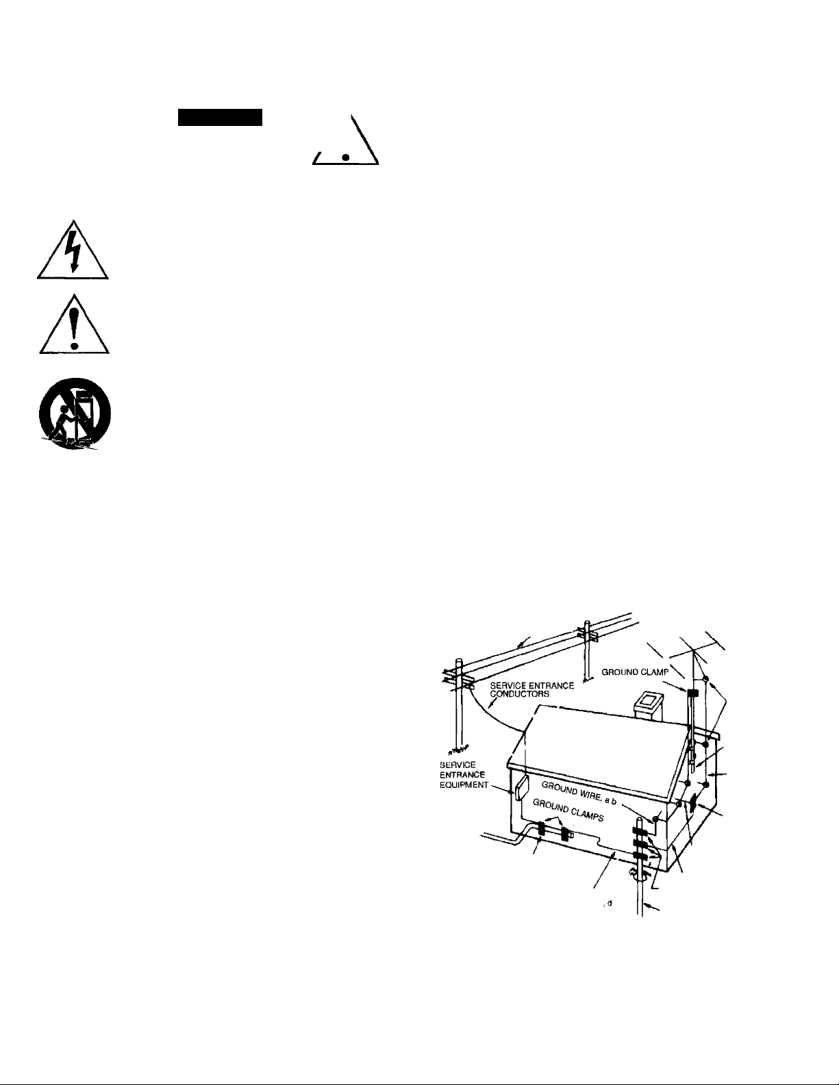
OUTDOOR ANTENNA GROUNDING
If an outside antenna is connected to your tuner or tuner-preamplifier, be
sure the antenna system is grounded so as to provide some protection
against voltage surges and built-up static charges. Section 810 of the
National Electrical Code, ANSI/NFPA No. 70-1984, provides Information with
respect to proper grounding of the mast and supporting structure, grounding
of the lead-in wire to an antenna discharge unit, size of grounding
conductors, location of antenna discharge unit, connection to grounding
electrodes, and requirements for the grounding electrode.
a. Use No.10 AWG (5.3 mm“’) copper, No.8 AWG (8.4 mm') aluminum,
No.17 AWG (1.0 mm') copper-clad steel or bronze wire, or larger, as a
ground wire.
b. Secure antenna lead-in and ground wires to house with stand-off
insulators spaced from 4-6 feet (1.22-1.83 m) apart.
c. Mount antenna discharge unit as close as possible to where lead-in
enters house.
d. Use jumper wire not smaller than No.6 AWG (13.3 mm') copper, or the
equivalent, when a separate antenna-grounding electrode is used. See NEC
Section 810-21 (j).
EXAMPLE OF ANTENNA GROUNDING AS PER NATIONAL ELECTRICAL CODE INSTRUCTIONS
CONTAINED IN ARTICLE 810 • RADIO AND TELEVISION EQUIPMENT.
The unit should be installed so that its location or position does not interfere
with its proper ventilation. For example, it should not be situated on a bed,
sofa, rug, or similar surface that may block the ventilation openings; or
placed in a built-in installation, such as bookcase or cabinet, that may
impede the flow of air through its ventilation openings.
The unit should be situated away from heat sources such as radiators, heat
registers, stoves, or other devices (including amplifiers) that produce heal.
The unit should be connected to a power-supply outlet only of the voltage
and frequency marked on its rear panel.
The power-supply cord should be routed so that it is not likely to be walked
on or pinched, especially near the plug, convenience receptacles, or where
the cord exits from the unit.
Clean unit only as recommended in its instruction manual.
The power-supply cord of the unit should be unplugged from the wall outlet
when it is to be unused for a long period of time.
Care should be taken so that objects do not fall, and liquids are not spilled,
into the enclosure through any openings.
This unit should be serviced by qualified service personnel when;
A. The power cord or the plug has been damaged; or
B. Objects have fallen, or liquid has been spilled, into the unit; or
C. The unit has been exposed to rain, or liquids of any kind; or
D. The unit does not appear to operate normally, or exhibits a
marked change in performance; or
E. The device has been dropped, or the enclosure damaged.
DO NOT ATTEMPT SERVICING OF THIS UNIT YOURSELF.
REFER SERVICING TO QUALIFIED SERVICE PERSONNEL.
POWER UNES
STANDOFF
INSULATORS, b
MAST
ANTENNA
LEAD-IN WIRE
ANTENNA
DISCHARGE
UNIT, c
TO EXTERNAL ANTEMNA
POWER SERVICE GROUNDING
ELECTRODE SYSTEM
(e. g. interior metal water pipe)
BONDING JUMPER,
OPTIONAL ANTENNA GROUNDING
ELECTRODE DRIVEN 8 FEET (2.44 M) INTO
THE EARTH IF REQUIRED BY LOCAL
CODES. SEE NEC SECTION 810-21 (f)
NOTE TO CATV SYSTEM INSTALLER
This reminder is provided to call the CATV system installer's attention to
Article 820-22 of the National Electrical Code that provides guidelines tor
proper grounding and, in particular, specifies that the cable ground shall be
connected to the grounding system of the building, as close to the point of
cable entry as practical.
TERMINALS OF RADIO RECEIVER
GROUND WIRE, a,b
GROUND CLAMPS
Page 3

INTRODUCTION
Congratulations on purchasing ADCOM's GCA-510 Control Amplifier, We designed this unique product for both simple
operation and exceptional sound quality, We don't anticipate any difficulty in setting up the GCA-510, but ask that you
do read the following instructions carefully before you begin hooking up your new component.
CIRCUIT DESIGN CONSIDERATIONS
The GCA-510 is an innovative example of the minimalist school of circuit design. Although it offers the convenience of
an "integrated amplifier,” it is actually a very high gain power amplifier preceded by a passive level controller. There is
no separate preamplifier stage in the GCA-510 at all.
The circuit topology includes a two stage discrete front end with doubly regulated and temperature compensated
active constant current bias sources. This gives exceptionally stable performance characteristics from DC to ultrasonic
frequencies.
The output stage utilizes a unique Bias-Emitter Multiplier to amplify a transistor's inherent silicon junction voltage to
create a temperature compensated constant voltage source. The complementary output stage features discrete high
power devices operated in a high-bias Class AB Common Collector mode. This design employs no current limiting.
Consequently, the amplifier Is completely capable of driving low impedance loads without excessive distortion. The
amplifier is also virtually impervious to speaker/cable reactance and will drive a fully phase shifted load with the same
distortion performance exhibited with a purely resistive load, Precise loudspeaker control is further assured by the
intentional elimination of output coils to provide a constant high damping factor over the entire audio range.
Page 4

FRONT and REAR PANELS
We carefully designed the GCA-510 with your enjoyment in mind, Controls are at a minimum and we’ve arranged them
so that their use is truly intuitive. The rear panel benefits from the same design goals. Take a moment to familiarize
yourself with the following drawings. You'll find references to the circled numbers throughout the rest of this manual.
GCA 510 - FRONT PANEL DIAGRAM
c
c
o
o
0
o
c
cd
o
o
"oT
£
_D
O
>
■0
>
CD
O
•4—'
o
<D
CO
U)
c
’c
CD
to
CD
x:
cj>
O
Q_
Q
LU
cO
o
ID
C.
o
Cl
_o
C33
C
ID
U—
o
o
o
cr
O
CD
(f)
Page 5

o Stereo (speaker) output - right channel
o Stereo (speaker) output - left channel
o Video input
0
Aux input
0
Ac (mains) fuse holder
0
Switched AC outlet (US models only)
o
0
>
1
at
o
JJ
m
>
5
z
m
1“
o
>
o
3J
>
0 CD input
0 Tuner input
0
Tape input
0
Tape output
0
Unswitched AC outlet (US models only)
Page 6

HOOK UP AND OPERATING INSTRUCTIONS
1} Unpack the GCA-510 carefully, Put the foam cocoon and other packing materials back in the carton and SAVE IT.
As part of ADCOM’s quality control procedures, your GCA-510 was carefully inspected for physical imperfections and
electrical performance before it left our plant. In the event of physical damage, notify your ADCOM dealer immediately and
request help in filing a written damage claim.
THE RIGHT TO A CLAIM AGAINST A COMMON CARRIER CAN BE FORFEITED IF THE CARRIER IS
NOT NOTIFIED PROMPTLY IN WRITING AND IF THE SHIPPING CARTON AND PACKING MATERIALS ARE
NOT AVAILABLE FOR INSPECTION. SAVE ALL PACKING MATERIALS UNTIL THE CLAIM HAS BEEN
SETTLED.
The foam cocoon and carton were specifically designed to protect your GCA-510. Even though space is often at a
premium in today’s homes, we recommend that you save the packing materials in case you need to ship the unit
anywhere in the future.
2) Select a stable, vibration-free location for the GCA-510 as close as possible to your other audio components. Make sure
you have enough air space for proper ventilation. We recommend at ieast 3" of free air space above the GCA-510 and an
inch to each side and to the rear of the unit.
The QCA-510 is heavier than you might expect due to the high capacity toroidal transformer and large heat sink assembly.
A stable supporting surface is necessary. We won't go into the endless and mostly unproved theories about extraneous
vibrations and their deleterious effects on audio components except to say that the more massive and firmly anchored the
supporting surface is, the less likely you’ll be to experience any problems.
Proper airflow is important. Don’t block the ventilation slots on the bottom plate and top cover of the unit. The feet will insure
enough air space below the GCA-510 tor adequate circulation. WE RECOMMEND THAT YOU DO NOT STACK OTHER
UNITS ON TOP OF THE GCA-510.
3) Turn off all the other components in your system. That means everything. And don’t plug the GCA-510 into the AC outlet
yet.
Turning off system components before initial installation and connection avoids the nasty buzzes, thumps, and other
sounds of electronic distress that occasionally accompanies hooking up components.
4) Connect the speakers to the 5-way binding posts (speaker outputs) of the GCA-510O& 0. The binding posts will
accept a variety of connectors from bare wire to exotic audiophile “super banana” types. Make sure to observe proper
polarity; Connect the GCA-510’s “+” (red) terminal for the left speaker to the terminal on that speaker. Do the same for
the terminals. Then repeat this for the right speaker.
Exercise care in connecting your speakers. Be particularly alert that individual strands of speaker wire do not short
between the “+” and terminals at either the amplifier or the speaker terminals.
A note on speaker cable: We recommend the use of at least 16 gauge (AWG) two conductor “zip” cord for all speaker
connections under 25' in length. For longer amplifier-to-speaker runs, we suggest 14 gauge “zip” cord. If you so desire,
specialty wire specifically designed for high quality amplifier-speaker interface may be considered. Consult your ADCOM
dealer for recommendations.
5) Connect the outputs of up to five (5) line level sources (CD player, tuner, etc.) to the appropriate inputs on the rear panel of
the GCA-510 ( 0 through O ). All Inputs are electrically identical.
Remember to observe proper channel continuity — left channel output to left channel input and right to right. The RCAtype input jacks on ADCOM products adhere to the color convention of white for left channel and red for right. Most dual
coaxial interconnect cables (or “patch “ cords) also follow this color coding or mark the cables in other obvious ways to
make channel continuity easy to establish.
A note on interconnects: We strongly recommend cables with low capacitance ratings. These will provide minimum
interference for component-to-component signal transfer. If you desire, you may opt for specialty interconnects specifically
designed for low loss signal transfer. Consult you ADCOM dealer for recommendations.
6) The “Tape Out” connections O should be connected to the inputs of your system’s tape or disc recorder. As long as you
do not attempt to run a patch cord from either channel’s ‘Tape Out” to a digital recorder’s digital input, you should
experience no problem.
If you do attempt this feat, you will not be punished. Nothing will happen. Absolutely nothing. Eventually, you'll realize the
mistake and correct it by connecting the GCA-510’s “Tape Out” jacks to the analog inputs of the digital recording device.
Then you'll be able to record.
The ‘Tape Out” jacks are buffered (or isolated) to preserve signal integrity under unusual load conditions. In other words,
the GCA-510's sound quality will be unaffected by any conditions inadvertently imposed by the recording device (low
impedances, electrical short circuits, etc.)
7) (This information applies only to certain versions of the GCA-510, Consult your dealer for details.)
The GCA-510 is equipped with two rear panel convenience AC outlets; one switched 0 and one unswitched Q. Power to
Page 7

the switched outlet is controlled by the front panel Power switch while the unswitched outlet carries AC current whenever the
GCA-510 is plugged into a live AC outlet. The power ratings for these outlets are as follows: 500 VA (equivalent to 500 watts)
maximum for the switched outlet and 800 VA (or watts) maximum for the unswitched outlet.
The switched outlet can be used for any system component that should be turned on or off when the GCA-510 is powered.
Tuners and CD players are the most likely candidates. The unswitched outlet is recommended for mechanical devices such as
a cassette deck where premature AC power interruption can result in damage to the drive assembly or for other source
components where a constant AC source is required to maintain internal settings.
After making sure that the “Level” control Ois turned completely down (counter-clockwise), plug the GCA-510 into an AC
8)
outlet, preferably one that is NOT controlled by a wall switch or other device that may be turned off inadvertently. If you live in an
area supplied with 115 Volt AC, we strongly recommend use of ADCOM’s ACE-515 AC line enhancer and sequential switcher.
See your ADCOM dealer for details.
Use the “Power” switch Oto turn the GCA-510 on. The “Power Indicator LED” O will light.
9)
10)
Select a. source for playback by rotating the “Listening” selector Oto the appropriate input position. You may select the same
source to record by rotating the “Recording” selector Oto the same input.
You can simultaneously select a totally different source for recording by simply selecting a different source with the “Record
ing” switch.
The GCA-510 will not allow a potentially destructive feedback condition even if you inadvertently set both the “Listening” and
“Recording” switches to the Tape position. In this case, the GCA-510 will automatically mute the recording output.
CARE AND FEEDING OF THE GCA-510
ADCOM has taken great care to assure that your GCA-510 is as flawless in appearance as it is electrically. The front panel is a
heavy-gauge, high grade anodized aluminum extrusion bead blasted for durability. The chassis, rear panel and top cover are
painted and baked heavy gauge steel.
If the outer cover or front panel becomes dusty or fingerprinted, please clean with a soft, lintless cloth, SLiGHTLY DAMPENED
with a very mild detergent solution.
DO NOT SPRAY OR USE LIQUIDS OF ANY KIND ON YOUR UNIT!
NEVER USE HARSH SCOURING POWDERS!
SERVICING
ADCOM’s Technical Service Department will be happy to answer all questions pertaining to the installation and operation of your
unit. In the unlikely event of difficulty, please contact us for prompt advice. If we can’t help you resolve the problem immediately,
we may refer you to an authorized repair agency, or authorize the return of your unit to our plant.
All written inquiries should be addressed to:
ADCOM Service Department
11 Elkins Road
East Brunswick, NJ.08816
USA
Telephone inquiries are welcomed from Monday through Friday between 9 AM and 4 PM, Eastern Time: (908)390-1130
We’ll also be happy to answer FAX inquiries. Direct them to: (908) 390-9152 and include your FAX number tor our response.
When inquiring about your unit, please include the serial number, the name of the dealer from whom you purchased the unit
and the date of purchase.
If we ask you to return the unit to us for service, we will issue a specific Return Authorization number for your use, UNDER
NO CIRCUMSTANCES SHOULD THE UNIT BE SHIPPED TO US WITHOUT PROPER AUTHORIZATION OR PACKED
IN ANYTHING OTHER THAN ITS ORIGINAL PACKING.
If the original packing has been lost, discarded or damaged, we will be happy to supply a replacement at a nominal
charge. Please mention your need when you call or write.
Always ship PREPAID via UPS (United Parcel Service) or other appropriate carrier. FREIGHT COLLECT SHIPMENTS
WILL BE REFUSED. DO NOT SHIP VIA PARCEL POST as the packaging will not necessarily withstand handling by our
Postal Service.
Page 8

GCA-510 SPECIFICATIONS
Power Rating (To FTC Requirements)
50 watts continuous average power into 8 ohms at any frequency between 20Hz and 20kHz with both channels driven
at iess then 0.075% THD.
75 watts continuous average power into 4 ohms at any frequency between 20Hz and 20kHz with both channels driven
at less then 0.075% THD.
iM Distortion (SlUIPTE)
1 watt to 50 watts into 8 ohms............................................................................................................................................^ 0.05%
1 watt to 75 watts into 4 ohms............................................................................................................................................0.05%
iM Distortion (CCiF, Any Combination from 4kHz to 20kHz)
50 watts into 8 ohms...........................................................................................................................................................^ 0.02%
75 watts into 4 ohms...........................................................................................................................................................— 0.02%
THD + Noise at 50 watts into 8 Ohms (Typical)
20Hz.....................................................................................................................................................................................0.012%
10kHz...................................................................................................................................................................................0.035%
20kHz.....................................................................................................................................................................................0.05%
THD + Noise at 75 watts into 4 Ohms (Typical)
20Hz.....................................................................................................................................................................................0.025%
1kHz.....................................................................................................................................................................................0,018%
10kHz.....................................................................................................................................................................................0.04%
20kHz...................................................................................................................................................................................0.055%
Frequency Response @ 1 Watt into 8 Ohms
10Hz to 20kHz....................................................................................................................................................................+0,-,5dB
Power Bandwidth (-3dB)...................................................................................................................................................3Hz to 100kHz
Dynamic Headroom into 4 Ohms...................................................................................................................................................2.3dB
Signal to Noise Ratio, “A” Weighted
50 watts into 8 ohms...........................................................................................................................................................> 105dB
Gain (Voume control @ Maximum).......................................................................................................................................................31 dB
Damping Factor
20Hzto 20kHz
Rise Time
5kHz, 65V peak to peak square wave, 20% to 80%................................................................................................................1.5us
Semiconductor complement.................................................................................................................33 transistors, 2 zener diodes,
Power Consumption (Continuous, Both Channels Driven)
Quiescent.................................................................................................................................................................................50VA
Maximum...............................................................................................................................................................................600VA
50 watts into 8 ohms..............................................................................................................................................................275VA
75 watts into 4 ohms..............................................................................................................................................................420VA
...........
;.............................................................................................................................................................>380
10 diodes, 1 IC, 1 diode bridge
General
Power (avaiiabie in 220V or 240V on special order)......................................................................................................120VAC/50-60Hz
Chassis Dimensions............................................................................................................3’(76mm) x 17"(432mm) x 11V4”(286mm)
Maximum Dimensions..........................................................................................................3V2”(89mm) x 17"(432mm) x 13''(330mm)
Weight...............................................................................................................................................................................15 lbs.(6,8kg)
Weight, Packed................................................................................................................................................................17,5 lbs,(7,9kg)
 Loading...