

ADC Corporation 6243, 6244 User Manual

Cover
6243/44
DC Voltage Current Source/Monitor
Operation Manual
MANUAL NUMBER
FOE-8440045E00
C
2007
ADC CORPORATION
All rights reserved.
First printing March 30, 2007
Printed in Japan


Safety Summary
Safety Summary
To ensure thorough understanding of all functions and to ensure efficient use of this instrument, please read the
manual carefully before using. Note that ADC Corporation (hereafter referred to as ADC) bears absolutely no responsibility for the result of operations caused due to incorrect or inappropriate use of this instrument.
If the equipment is used in a manner not specified by ADC, the protection provided by the equipment may be impaired.
• Warning Labels
Warning labels are applied to ADC products in locations where specific dangers exist. Pay careful attention to these labels during handling. Do not remove or tear these labels. If you have any
questions regarding warning labels, please ask your nearest ADC dealer. Our address and phone
number are listed at the end of this manual.
Symbols of those warning labels are shown below together with their meaning.
DANGER: Indicates an imminently hazardous situation which will result in death or serious
WARNING: Indicates a potentially hazardous situation which will result in death or serious
CAUTION: Indicates a potentially hazardous situation which will result in personal injury or
• Basic Precautions
Please observe the following precautions to prevent fire, burn, electric shock, and personal injury.
• Use a power cable rated for the voltage in question. Be sure however to use a power cable
conforming to safety standards of your nation when using a product overseas.
• When inserting the plug into the electrical outlet, first turn the power switch OFF and then
insert the plug as far as it will go.
• When removing the plug from the electrical outlet, first turn the power switch OFF and then
pull it out by gripping the plug. Do not pull on the power cable itself. Make sure your hands
are dry at this time.
• Before turning on the power, be sure to check that the supply voltage matches the voltage
requirements of the instrument.
personal injury.
personal injury.
a damage to property including the product.
FOE-ANZENA00
• Connect the power cable to a power outlet that is connected to a protected ground terminal.
Grounding will be defeated if you use an extension cord which does not include a protective
conductor terminal.
• Be sure to use fuses rated for the voltage in question.
• Do not use this instrument with the case open.
• Do not place anything on the product and do not apply excessive pressure to the product. Also, do not place flower pots or other containers containing liquid such as chemicals near this
Safety-1
Safety Summary
product.
• When the product has ventilation outlets, do not stick or drop metal or easily flammable objects into the ventilation outlets.
• When using the product on a cart, fix it with belts to avoid its drop.
• When connecting the product to peripheral equipment, turn the power off.
• Caution Symbols Used Within this Manual
Symbols indicating items requiring caution which are used in this manual are shown below together with their meaning.
DANGER: Indicates an item where there is a danger of serious personal injury (death or seri-
ous injury).
WARNING: Indicates an item relating to personal safety or health.
CAUTION: Indicates an item relating to possible damage to the product or instrument or relat-
ing to a restriction on operation.
• Safety Marks on the Product
The following safety marks can be found on ADC products.
: ATTENTION - Refer to manual.
: Protective ground (earth) terminal.
: DANGER - High voltage.
: CAUTION - Risk of electric shock.
• Replacing Parts with Limited Life
The following parts used in the instrument are main parts with limited life.
Replace the parts listed below before their expected lifespan has expired to maintain the performance and function of the instrument.
Note that the estimated lifespan for the parts listed below may be shortened by factors such as
the environment where the instrument is stored or used, and how often the instrument is used.
The parts inside are not user-replaceable. For a part replacement, please contact the ADC sales
office for servicing.
Safety-2
Each product may use parts with limited life.
For more information, refer to the section in this document where the parts with limited life are
described.
FOE-ANZENA00

Main Parts with Limited Life
Part name Life
Unit power supply 5 years
Fan motor 5 years
Electrolytic capacitor 5 years
LCD display 6 years
LCD backlight 2.5 years
Floppy disk drive 5 years
Memory backup battery 5 years
• Hard Disk Mounted Products
The operational warnings are listed below.
• Do not move, shock and vibrate the product while the power is turned on.
Reading or writing data in the hard disk unit is performed with the memory disk turning at a
high speed. It is a very delicate process.
Safety Summary
• Store and operate the products under the following environmental conditions.
An area with no sudden temperature changes.
An area away from shock or vibrations.
An area free from moisture, dirt, or dust.
An area away from magnets or an instrument which generates a magnetic field.
• Make back-ups of important data.
The data stored in the disk may become damaged if the product is mishandled. The hard disc
has a limited life span which depends on the operational conditions. Note that there is no
guarantee for any loss of data.
• Precautions when Disposing of this Instrument
When disposing of harmful substances, be sure dispose of them properly with abiding by the
state-provided law.
Harmful substances: (1) PCB (polycarbon biphenyl)
(2) Mercury
(3) Ni-Cd (nickel cadmium)
(4) Other
Items possessing cyan, organic phosphorous and hexadic chromium
and items which may leak cadmium or arsenic (excluding lead in solder).
Example: fluorescent tubes, batteries
FOE-ANZENA00
Safety-3
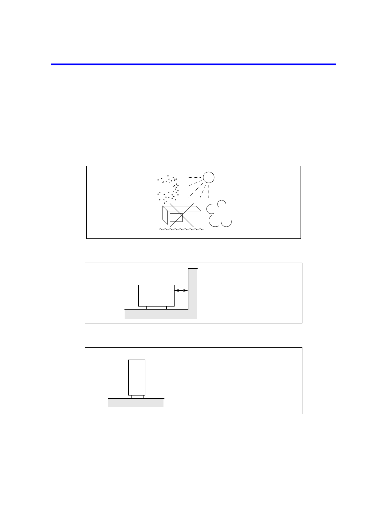
Environmental Conditions
This instrument should be only be used in an area which satisfies the following conditions:
• An area free from corrosive gas
• An area away from direct sunlight
• A dust-free area
• An area free from vibrations
• Altitude of up to 2000 m
Direct sunlight
Dust
Corrosive
gas
Vibration
Figure-1 Environmental Conditions
• Operating position
A clear space of 10 centimeters or more
must be kept around the air vents.
Front
Figure-2 Operating Position
• Storage position
Front
• The classification of the transient over-voltage, which exists typically in the main power supply, and
the pollution degree is defined by IEC61010-1 and described below.
Impulse withstand voltage (over-voltage) category II defined by IEC60364-4-443
This instrument should be stored in a horizontal
position.
When placed in a vertical (upright) position for
storage or transportation, ensure the instrument is
stable and secure.
-Ensure the instrument is stable.
-Pay special attention not to fall.
Figure-3 Storage Position
The instrument must be used in a horizontal position.
To prevent the internal temperature
from rising, cooling fans are installed
in some instruments.
The air vents on the case must be unblocked.
Safety-4
Pollution Degree 2
FOE-ANZENA00
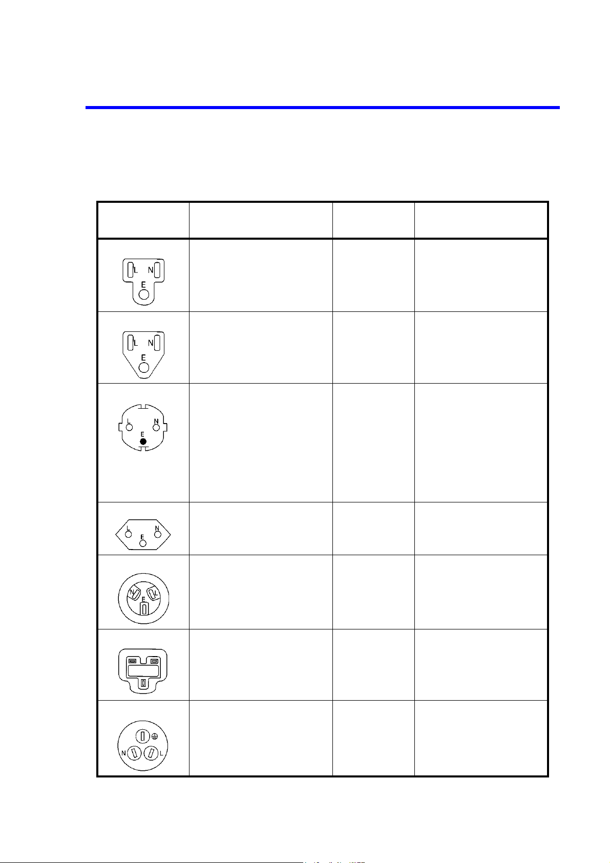
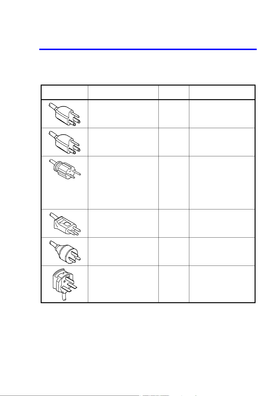
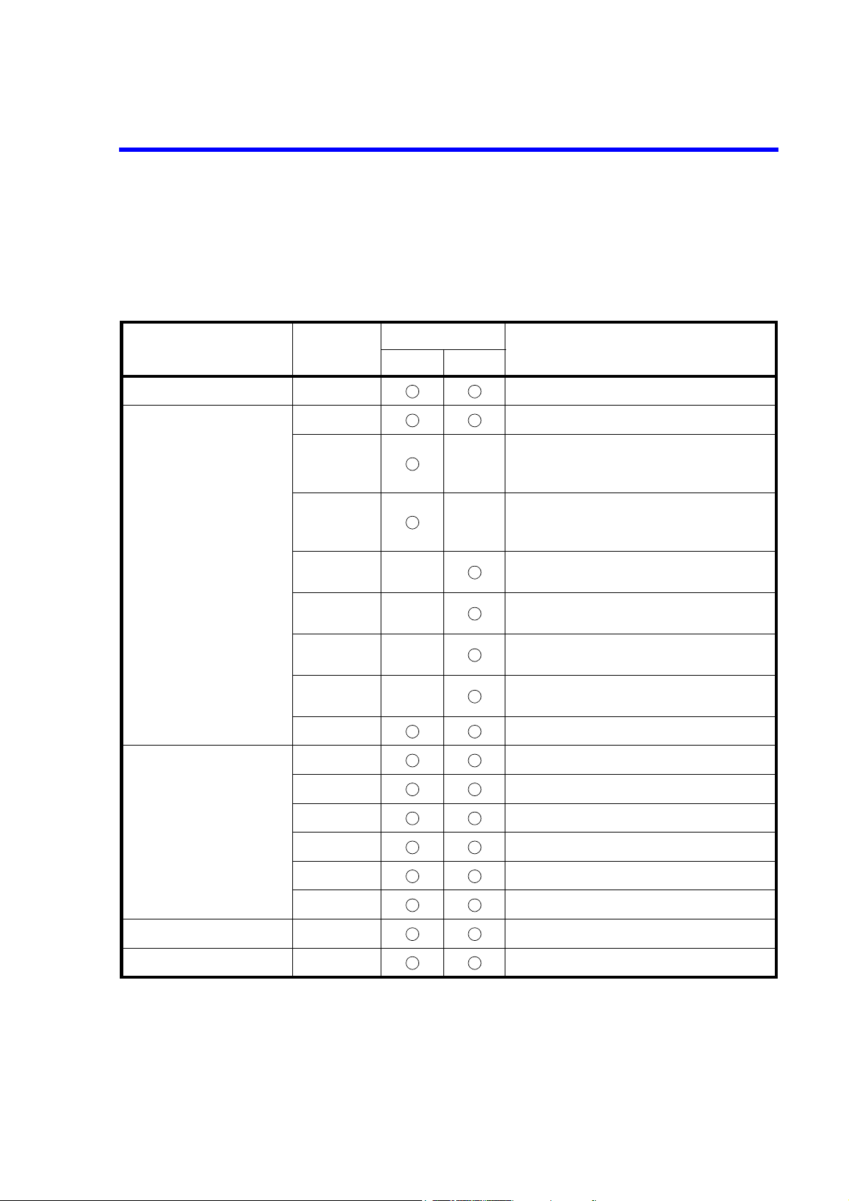
Types of Power Cable
Replace any references to the power cable type, according to the following table, with the appropriate power cable
type for your country.
Plug configuration Standards
PSE: Japan
Electrical Appliance and
Material Safety Law
UL: United States of America
CSA: Canada
CEE: Europe
DEMKO: Denmark
NEMKO: Norway
VDE: Germany
KEMA: The Netherlands
CEBEC: Belgium
OVE: Austria
FIMKO: Finland
SEMKO: Sweden
Rating, color
and length
125 V at 7 A
Black
2 m (6 ft)
125 V at 7 A
Black
2 m (6 ft)
250 V at 6 A
Gray
2 m (6 ft)
Model number
(Option number)
Straight: A01402
Angled: A01412
Straight: A01403
(Option 95)
Angled: A01413
Straight: A01404
(Option 96)
Angled: A01414
FOE-ANZENA00
SEV: Switzerland 250 V at 6 A
Gray
2 m (6 ft)
SAA: Australia, New Zealand 250 V at 6 A
Gray
2 m (6 ft)
BS: United Kingdom 250 V at 6 A
Black
2 m (6 ft)
CCC:China 250 V at 10 A
Black
2 m (6 ft)
Straight: A01405
(Option 97)
Angled: A01415
Straight: A01406
(Option 98)
Angled: ---------
Straight: A01407
(Option 99)
Angled: A01417
Straight: A114009
(Option 94)
Angled: A114109
Safety-5


SAFETY PRECAUTIONS FOR THE 6243/44
6243/44 DC Voltage Current Source/Monitor Operation Manual
SAFETY PRECAUTIONS FOR THE 6243/44
Confirm all of the following points before connecting the 6243/44 and the DUT to prevent destruction of the
DUT due to an overload of voltage or current:
• The 6243/44 is in the standby mode. (OPERATE lamp is off.)
• No error or failure indication is displayed.
• The 6243/44 is grounded. (The ground pin of the power cable is grounded.)
• When using an ADC CORPORATION manufactured test fixture, connecting the INTERLOCK terminal to the LID SIGNAL on the test fixture makes it possible to set the output to standby status by
opening and closing the lid.
When mounting the 6243/44 in a rack
• Make sure that the rack does not topple over if the 6243/44 is off balance.
• Be careful that the rack does not topple over when the slide rail is pulled out.
When the 6243/44 is used in the TR6143 Mode 1
The voltage limiter of the current source function only operates using the same polarity as that of the
source.
When the current source value is set to +0 A in the no-load status, or when negative current is generated
due to an error, the output terminal may deliver a negative supply voltage. (6243; -130 V, 6244; -26 V)
If these conditions pose a problem, use one of the following procedures.
• Set the value of current source to 10 counts or higher at all times.
• Use the Original Mode.
• Use the TR6143 Mode 2.
(In TR6143 Mode 2, the GPIB commands are the same as in TR6143 Mode 1. However, the hardware configuration is the same as the 6243/44 so the voltage limiter operates using both polarities.)
Caution-1


Certificate of Conformity
Certificate of Conformity
This is to certify, that
DC Voltage Current Source/Monitor
6243
instrument, type, designation
complies with the provisions of the EMC Directive 89/336/EEC (All of these factors are
revised by 91/263/EEC, 92/31/EEC, 93/68/EEC), 2004/108/EC in accordance with EN61326
and Low Voltage Directive 73/23/EEC (All of these factors are revised by 93/68/EEC),
2006/95/EC in accordance with EN61010.
ADC Corp. ROHDE&SCHWARZ
Japan Europe GmbH
Munich, Germany
6243.03

Certificate of Conformity
This is to certify, that
DC Voltage Current Source/Monitor
6244
instrument, type, designation
complies with the provisions of the EMC Directive 89/336/EEC (All of these factors are
revised by 91/263/EEC, 92/31/EEC, 93/68/EEC), 2004/108/EC in accordance with EN61326
and Low Voltage Directive 73/23/EEC (All of these factors are revised by 93/68/EEC),
2006/95/EC in accordance with EN61010.
ADC Corp. ROHDE&SCHWARZ
Japan Europe GmbH
Munich, Germany
6244.03

PREFACE
6243/44 DC Voltage Current Source/Monitor Operation Manual
PREFACE
This document describes the operations, functions and remote programming of 6243/44 DC Voltage/Current
Source/Monitor operations.
This document refers the 6243/44 ROM version B00 or later. (To confirm the ROM version, refer to Section 1.5,
“Operational Check.”)
The following functions are not available for the 6243/44 ROM version A02 or earlier.
• Function for switching the pulse width for external single-line output
The default is always set to 20 μs.
• TR6143 Mode 2 function
Only the Original Mode and TR6143 Mode 1 functions are available.
1. Contents of this Manual
This document consists of the following chapters:
Safety Summary Read before using the 6243/44
1. INTRODUCTION Describes the supplied accessories,
operating environment, and how to check the 6243/44
correctly.
2. OPERATION Describes the front and rear panel operation.
3. REFERENCE The buttons and keys on the front panel, parameter
4. PRACTICAL GUIDE FOR MEASURE-
MENTS
5. REMOTE PROGRAMMING
6. COMPATIBILITY WITH TR6143
7. PERFORMANCE TESTS
8. CALIBRATION
9. SPECIFICATIONS
Basic operation and measurement examples are given.
groups, parameter items, and functions are explained.
Explains, in detail, functions used to
perform measurements accurately.
Explains the GPIB interface, hardware connections, the
GPIB setup, and lists GPIB commands and programming
examples.
Explains the TR6143 compatibility.
Explains operations used to confirm that the 6243/44 is
operating correctly within acceptable limits.
Explains how to calibrate the 6243/44 to ensure
operation within acceptable limits.
Describes the 6243/44s specifications.
A.1 When Problems Occur (Before Requesting
Repairs)
A.2 Error Message List Error messages are explained here.
DIMENSIONAL OUTLINE DRAWING External dimensions: Describes the external dimensions.
Troubleshooting.
Preface-1

6243/44 DC Voltage Current Source/Monitor Operation Manual
PREFACE
2. Notational Conventions Used in This Document
In this document, panel keys, parameter groups, parameter items, and parameters are indicated in the following way:
• Panel keys: Bold (Example: MODE, MENU)
• Parameter groups, parameter items, parameters: Bold and italic (Example: SWEEP TYPE, Measure
Delay)
When keys are pressed sequentially in an operating procedure, Key names are separated by a “,” (comma) in
this manual.
When common function of both the 6243 and 6244 are described, diagrams of either the 6243 or 6244 are
used.
Preface-2

TABLE OF CONTENTS
6243/44 DC Voltage Current Source/Monitor Operation Manual
TABLE OF CONTENTS
1. INTRODUCTION ....................................................................................... 1-1
1.1 Product Overview .............................................................................................. 1-1
1.2 Supplied Accessories ........................................................................................ 1-3
1.3 Optional Accessories ......................................................................................... 1-5
1.4 Operating Environment ..................................................................................... 1-6
1.4.1 Environmental Conditions .......................................................................... 1-6
1.4.2 Power Supply Conditions ........................................................................... 1-7
1.4.3 Changing the Source Voltage Setting and Checking/Replacing the Fuse .. 1-8
1.4.4 Power Cable ................................................................................................ 1-9
1.4.5 Warm-up (Preheating Time) ....................................................................... 1-9
1.5 Operational Check ............................................................................................. 1-10
1.6 Setting the Line Frequency ............................................................................... 1-13
1.7 Cleaning, Storage, and Transport Methods ....................................................... 1-15
1.7.1 Cleaning ...................................................................................................... 1-15
1.7.2 Storage ........................................................................................................ 1-15
1.7.3 Transport ..................................................................................................... 1-15
1.8 Calibration ......................................................................................................... 1-16
1.9 Parts with a Limited Life Span .......................................................................... 1-16
2. OPERATION ................................................................................................ 2-1
2.1 Panel Descriptions ............................................................................................. 2-1
2.1.1 Front Panel Summary ................................................................................. 2-1
2.1.2 Screen Display ............................................................................................ 2-5
2.1.3 Rear Panel Summary .................................................................................. 2-7
2.2 Basic Operations ............................................................................................... 2-10
2.2.1 Setting the Source and Limiter Values ....................................................... 2-10
2.2.2 Menu Operations and Parameter Settings .................................................. 2-13
2.2.3 DC Measurement ........................................................................................ 2-15
2.2.4 Pulse Mode Measurement .......................................................................... 2-19
2.2.5 Sweep Mode Measurement ........................................................................ 2-24
2.3 Measurement Example ...................................................................................... 2-30
2.3.1 Measuring a Diode ..................................................................................... 2-30
2.3.2 Battery Charge Test and Discharge Test .................................................... 2-36
2.4 Saving and Loading Parameters ........................................................................ 2-43
3. REFERENCE ................................................................................................ 3-1
3.1 Menu Index ....................................................................................................... 3-1
3.2 Menu Map ......................................................................................................... 3-3
3.3 Panel Keys and Parameters ............................................................................... 3-7
3.3.1 AUTO key (Measurement Range) .............................................................. 3-7
3.3.2 DIRECT key (Direct Input Mode) ............................................................. 3-7
3.3.3 ENTER (DIRECT) key (Confirming Numeric Values) ............................. 3-7
3.3.4 EXIT key (Normal Measurement Screen) .................................................. 3-7
3.3.5 GP-IB LOCAL key (GPIB Remote Control) ............................................. 3-7
C-1

6243/44 DC Voltage Current Source/Monitor Operation Manual
Table of Contents
3.3.6 LIMIT key (Limiter Setting) ...................................................................... 3-8
3.3.7 MENU key (Setting Parameters) ................................................................ 3-8
3.3.7.1 SWEEP (Sweep Parameters) ...................................................................... 3-8
3.3.7.2 TIME (Time Parameters) ........................................................................... 3-10
3.3.7.3 SOURCE (Source Parameters) ................................................................... 3-10
3.3.7.4 MEASURE (Measurement Parameters) ..................................................... 3-11
3.3.7.5 COMPARATOR (Comparison Operation Parameters) ............................. 3-12
3.3.7.6 EXT.SIGNAL (External Control Signal Parameters) ................................ 3-12
3.3.7.7 SYSTEM (System Parameters) .................................................................. 3-14
3.3.7.8 RANDOM MEMORY (Random Memory Settings) ................................. 3-15
3.3.7.9 MEASURE BUFFER (Measurement Buffer Memory) ............................. 3-15
3.3.7.10 PARAMETER SAVE (Saving Parameters) ............................................... 3-16
3.3.7.11 PARAMETER LOAD (Loading Parameters) ............................................ 3-16
3.3.8 MODE key (Source Mode) ........................................................................ 3-17
3.3.9 NULL key (NULL Calculation) ................................................................. 3-17
3.3.10 OPERATE key (Output ON/OFF) ............................................................. 3-17
3.3.11 POLARITY key (Source Polarity) ............................................................. 3-17
3.3.12 RANGE key (Source Range) ...................................................................... 3-18
3.3.13 RECALL key (Measurement Data Recall) ................................................. 3-18
3.3.14 RUN HOLD key (Measurement Free Run/Hold) ...................................... 3-18
3.3.15 START TRIGGER key (Sweep Start, Measurement Trigger) ................... 3-18
3.3.16 STOP key (Sweep Stop) ............................................................................. 3-18
3.3.17 VM/IM key (Measurement Functions) ....................................................... 3-19
3.3.18 VS/IS key (Source Functions) .................................................................... 3-19
3.4 List of Settings .................................................................................................. 3-20
3.4.1 6243 Setting Ranges and Factory Settings ................................................. 3-20
3.4.2 6244 Setting Ranges and Factory Settings ................................................. 3-22
4. PRACTICAL GUIDE FOR MEASUREMENTS ................................ 4-1
4.1 DUT Connection ............................................................................................... 4-1
4.1.1 Precautions for the Output Terminals (Front and Rear Output Terminals) 4-1
4.1.2 Remote Sensing (2-wire/4-wire Connection) ............................................. 4-2
4.1.3 Driving Guard (6243 Only) ........................................................................ 4-5
4.1.4 Oscillation Prevention ................................................................................ 4-5
4.1.4.1 SMU (Source Measurement Unit) Oscillation Prevention ......................... 4-5
4.1.4.2 Oscillation of the Device Itself ................................................................... 4-7
4.1.5 Connection for High-Current Measurement ............................................... 4-8
4.1.6 Connecting to the Fixture 12701A ............................................................. 4-9
4.2 Operation in the DC Source Mode .................................................................... 4-10
4.3 Operation in the Pulse Source Mode ................................................................. 4-12
4.4 Operation in the Sweep Source Mode ............................................................... 4-14
4.4.1 Staircase Sweep .......................................................................................... 4-15
4.4.2 Pulse Sweep ................................................................................................ 4-17
4.4.3 Random Sweep and Random Pulse Sweep ................................................ 4-19
4.4.4 Round-Trip Sweep (Reverse ON) .............................................................. 4-20
4.5 Source Functions ............................................................................................... 4-21
4.5.1 Changing the Source Mode and Source Function ...................................... 4-21
4.5.2 Source value Restrictions ........................................................................... 4-22
4.5.3 Source Range .............................................................................................. 4-23
C-2

6243/44 DC Voltage Current Source/Monitor Operation Manual
Table of Contents
4.5.4 Polarity Change .......................................................................................... 4-26
4.5.5 Reverse Polarity Source Operation ............................................................ 4-28
4.6 Measurement Function ...................................................................................... 4-29
4.6.1 Measurement Function ............................................................................... 4-29
4.6.2 Measurement Ranging ................................................................................ 4-29
4.6.3 Auto-Zero Function .................................................................................... 4-33
4.7 Limiter (Compliance) ........................................................................................ 4-34
4.7.1 Limiter Setting Ranges ............................................................................... 4-34
4.7.2 Limiter Polarity Mode ................................................................................ 4-37
4.8 Alarm Detection ................................................................................................ 4-38
4.9 Source Timing and Measurement Timing ......................................................... 4-40
4.9.1 Restrictions on Time Parameters ................................................................ 4-41
4.9.2 Measure Delay and Settling Time .............................................................. 4-44
4.9.3 Integration Time and Measurement Time .................................................. 4-47
4.9.4 Auto Range Delay ...................................................................................... 4-48
4.10 Computing Functions ........................................................................................ 4-50
4.10.1 NULL Calculation ...................................................................................... 4-50
4.10.2 Comparator Calculation .............................................................................. 4-51
4.11 External Control Signals ................................................................................... 4-52
4.11.1 Signal Timing ............................................................................................. 4-54
4.11.2 Control of Scanner ...................................................................................... 4-55
4.12 Synchronized Operation, Serial Connection, and Parallel Connection ............. 4-56
4.12.1 Synchronized Operation ............................................................................. 4-56
4.12.2 Serial Connection ....................................................................................... 4-58
4.12.3 Parallel Connection .................................................................................... 4-59
4.13 Measurement Data Storing Function ................................................................ 4-60
4.13.1 Storing Measured Data into Data Memory (Memory Store) ...................... 4-60
4.13.2 Clearing Saved Data (Memory Clear) ........................................................ 4-62
4.14 Operating Principles .......................................................................................... 4-63
4.14.1 Block Diagram ............................................................................................ 4-63
4.14.2 Operating Principles ................................................................................... 4-64
5. REMOTE PROGRAMMING ................................................................... 5-1
5.1 GPIB Command Index ...................................................................................... 5-1
5.2 GPIB Remote Programming ............................................................................. 5-4
5.2.1 What GPIB Is ............................................................................................. 5-4
5.2.2 GPIB Setup ................................................................................................. 5-4
5.2.3 GPIB Interface Functions ........................................................................... 5-7
5.2.4 Responses to Interface Messages ............................................................... 5-7
5.2.5 Message Exchange Protocol ....................................................................... 5-9
5.2.6 Command Syntax ....................................................................................... 5-9
5.2.7 Data Format ................................................................................................ 5-10
5.2.8 Status Byte .................................................................................................. 5-11
5.2.9 Date Output Format (Talker) ...................................................................... 5-18
5.2.10 GPIB Code List .......................................................................................... 5-21
5.2.10.1 GPIB Code List .......................................................................................... 5-21
5.2.10.2 TER? Command Response ......................................................................... 5-30
5.2.11 Program Examples ...................................................................................... 5-32
C-3

6243/44 DC Voltage Current Source/Monitor Operation Manual
Table of Contents
5.2.11.1 Program Example 1: DC Measurement ...................................................... 5-32
5.2.11.2 Program Example 2: Pulse Measurement ................................................... 5-34
5.2.11.3 Program Example 3: Sweep Measurement ................................................. 5-36
5.2.11.4 Program Example 4: Diode Measurement ................................................. 5-38
5.2.11.5 Program Example 5: Using Measurement Buffer Memory ....................... 5-40
6. COMPATIBILITY WITH TR6143 ......................................................... 6-1
6.1 Setting the TR6143 Mode ................................................................................. 6-1
6.2 Differences Between the TR6143 Mode and the Original Mode ..................... 6-3
6.3 List of Defaults in the TR6143 Mode ............................................................... 6-5
6.3.1 6243 Default Values ................................................................................... 6-5
6.3.2 6244 Default Values ................................................................................... 6-7
6.4 GPIB in the TR6143 Mode ............................................................................... 6-9
6.4.1 TR6143 Mode GPIB Code List .................................................................. 6-9
6.4.2 Data Output Format in the TR6143 Mode (Talker) ................................... 6-12
6.4.3 Status Byte in TR6143 Mode ..................................................................... 6-20
7. PERFORMANCE TESTS ......................................................................... 7-1
7.1 6243 Tests ......................................................................................................... 7-1
7.1.1 Measuring Instruments Required for Performance Tests ........................... 7-1
7.1.2 Connections ................................................................................................ 7-1
7.1.3 Test Methods .............................................................................................. 7-1
7.2 6244 Tests ......................................................................................................... 7-3
7.2.1 Measuring Instruments Required for Performance Tests ........................... 7-3
7.2.2 Connections ................................................................................................ 7-3
7.2.3 Test Methods .............................................................................................. 7-3
8. CALIBRATION ........................................................................................... 8-1
8.1 6243 Calibration ................................................................................................ 8-1
8.1.1 Cables and Measuring Instruments Required for Calibration .................... 8-1
8.1.2 Safety Precautions ...................................................................................... 8-2
8.1.3 Connections ................................................................................................ 8-3
8.1.4 Calibration Points and Tolerance Range .................................................... 8-4
8.1.5 Calibration Procedure ................................................................................. 8-4
8.1.6 Initializing Calibration Data ....................................................................... 8-9
8.2 6244 Calibration ................................................................................................ 8-10
8.2.1 Cables and Measuring Instruments Required for Calibration .................... 8-10
8.2.2 Safety Precautions ...................................................................................... 8-10
8.2.3 Connections ................................................................................................ 8-11
8.2.4 Calibration Points and Tolerance Range .................................................... 8-12
8.2.5 Calibration Procedure ................................................................................. 8-12
8.2.6 Initializing Calibration Data ....................................................................... 8-17
9. SPECIFICATIONS ...................................................................................... 9-1
9.1 6243 Specifications ........................................................................................... 9-1
9.1.1 Voltage/Current Source .............................................................................. 9-1
9.1.2 Voltage/Current Measurement ................................................................... 9-6
C-4

6243/44 DC Voltage Current Source/Monitor Operation Manual
Table of Contents
9.1.3 Source and Measurement Functions ........................................................... 9-9
9.1.4 Setting Time ............................................................................................... 9-10
9.1.5 General Specifications ................................................................................ 9-11
9.2 6244 Specifications ........................................................................................... 9-12
9.2.1 Voltage/Current Source .............................................................................. 9-12
9.2.2 Voltage/Current Measurement ................................................................... 9-17
9.2.3 Source and Measurement Functions ........................................................... 9-20
9.2.4 Setting Time ............................................................................................... 9-21
9.2.5 General Specifications ................................................................................ 9-23
APPENDIX ................................................................................................................. A-1
A.1 When Problems Occur (Before Requesting Repairs) ........................................ A-1
A.2 Error Message List ............................................................................................ A-3
A.3 Execution Time ................................................................................................. A-5
A.3.1 GPIB Remote Execution Time (Nominal Values) ..................................... A-5
A.3.2 Internal Execution Time (Nominal Values) ............................................... A-8
6243 DIMENSIONAL OUTLINE DRAWING................................................ EXT-1
6244 DIMENSIONAL OUTLINE DRAWING................................................ EXT-2
ALPHABETICAL INDEX ..................................................................................... I-1
C-5


6243/44 DC Voltage Current Source/Monitor Operation Manual
LIST OF ILLUSTRATIONS
No. Title Page
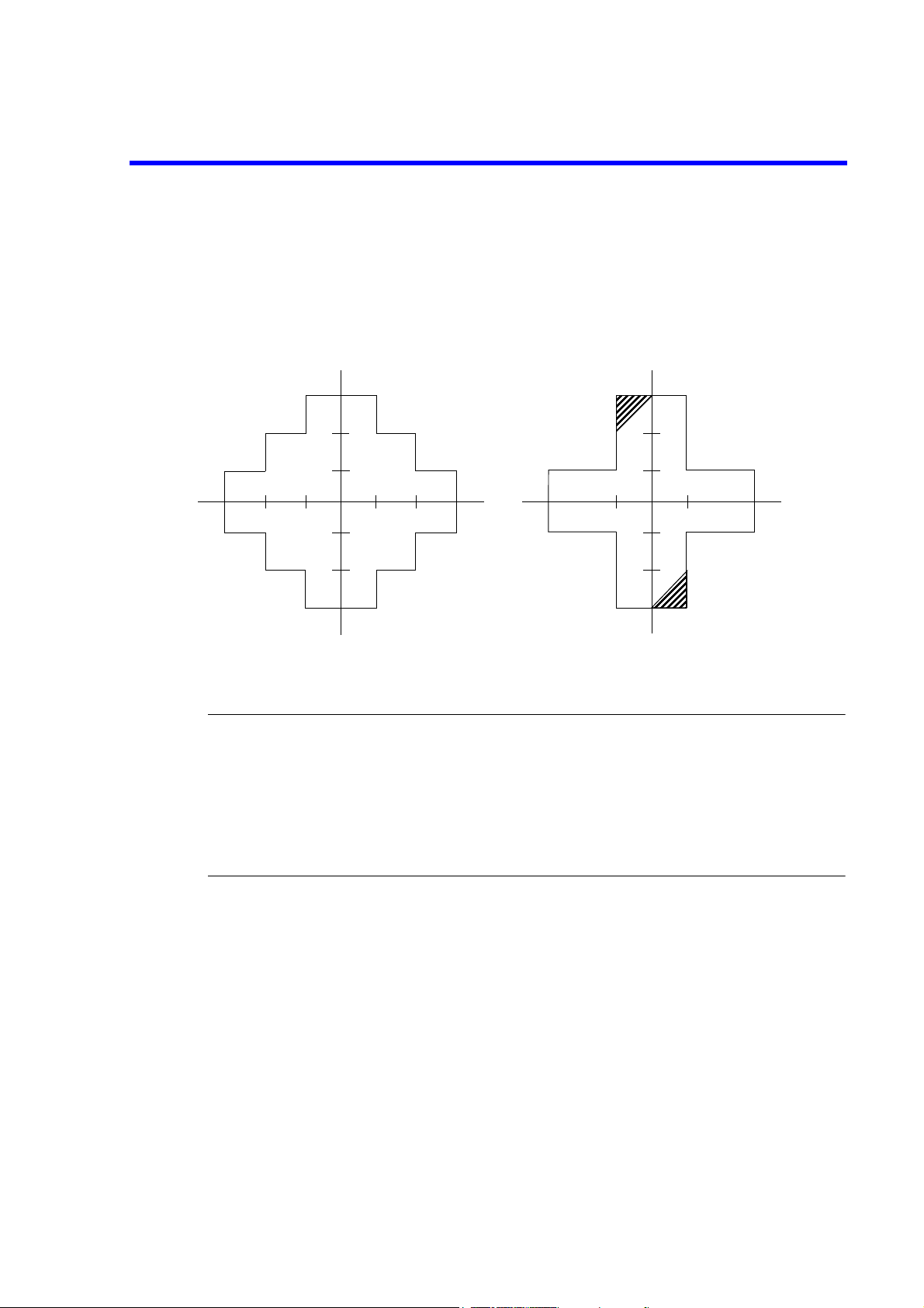
1-1 Output Range .................................................................................................................... 1-2
1-2 Operating Environment ..................................................................................................... 1-7
1-3 Changing the Source Voltage Setting and Checking/Replacing the Fuse ........................ 1-8
1-4 Power Cable ...................................................................................................................... 1-9
1-5 Connecting the Power Cable ............................................................................................. 1-10
1-6 Display during Self test ..................................................................................................... 1-11
1-7 Display when Self test is Completed ................................................................................ 1-11
1-8 Start-up Screen .................................................................................................................. 1-11
1-9 VSVM Measurement (In Output OFF Standby) ............................................................... 1-12
1-10 VSVM 320 mV Range 0 V Measurement ........................................................................ 1-12
2-1 Front Panel (6243) ............................................................................................................ 2-1
2-2 Front Panel (6244) ............................................................................................................ 2-2
2-3 Screen Element Descriptions ............................................................................................ 2-5
2-4 Rear Panel (6243) ............................................................................................................. 2-7
2-5 Rear Panel (6244) ............................................................................................................. 2-7
2-6 Menu Structure (MENU key) ........................................................................................... 2-14
2-7 Explanatory Drawing of DC Measurement ...................................................................... 2-15
2-8 Pulse Mode Measurement ................................................................................................. 2-19
2-9 Sweep Mode Measurement ............................................................................................... 2-24
2-10 Connections for Diode Measurement ............................................................................... 2-31
2-11 Waveform of Battery Discharge Test ............................................................................... 2-37
2-12 Connections for Battery Charge and Discharge Test ........................................................ 2-38
2-13 Parameter Saving and Loading Operations ...................................................................... 2-43
4-1 Internal Wiring (6243) ...................................................................................................... 4-1
4-2 Internal Wiring (6244) ...................................................................................................... 4-2
4-3 2 Wire / 4 Wire Connections ............................................................................................ 4-3
4-4 Reducing Stray Capacitance and Lead Inductance ........................................................... 4-6
4-5 Device Oscillation Prevention .......................................................................................... 4-7
4-6 SMU Oscillation Prevention ............................................................................................. 4-7
4-7 Connection for Heavy-Current Measurement ................................................................... 4-8
4-8 Connecting to the 12701A ................................................................................................ 4-9
4-9 Staircase Sweep (One-Way Sweep) ................................................................................. 4-16
4-10 Pulse Sweep (One-Way Sweep) ....................................................................................... 4-18
4-11 Operations of Random Sweep and Random Pulse Sweep ................................................ 4-19
4-12 Round-Trip Sweep (Reverse ON) ..................................................................................... 4-20
4-13 Changing the Source Mode and Source Function ............................................................ 4-21
4-14 Range Operation during Sweep ........................................................................................ 4-25
4-15 Sweep Operation Straddling Polarities ............................................................................. 4-27
4-16 Reverse Polarity Source Operation ................................................................................... 4-28
4-17 Current Measurement in Auto Range and Limiter Operation (1/2) .................................. 4-30
4-17 Current Measurement in Auto Range and Limiter Operation (2/2) .................................. 4-30
4-18 Auto Ranging during Sweep Mode Measurement ............................................................ 4-32
4-19 Output Waveform in Accordance With Time Parameters ................................................ 4-43
4-20 Timing of NULL Calculation ........................................................................................... 4-50
F-1

6243/44 DC Voltage Current Source/Monitor Operation Manual
List of Illustrations
No. Title Page
4-21 Timing of External Control Signals .................................................................................. 4-54
4-22 Control of Scanner ............................................................................................................ 4-55
4-23 Synchronized Operation Using the BUSY Signal ............................................................ 4-57
4-24 Serial Connection .............................................................................................................. 4-58
4-25 Parallel Connection ........................................................................................................... 4-59
4-26 Conceptual Diagram of Storing Measured Data ............................................................... 4-60
4-27 Block Diagram of Source and Measurement Sections ..................................................... 4-63
5-1 Structure of Status Registers ............................................................................................. 5-12
5-2 Structure of Status Byte Register ...................................................................................... 5-13
8-1 Connections for Calibration .............................................................................................. 8-3
8-2 Overview of the Calibration Procedure ............................................................................ 8-4
8-3 Connections for Calibration .............................................................................................. 8-11
8-4 Overview of Calibration Procedure .................................................................................. 8-12
F-2

6243/44 DC Voltage Current Source/Monitor Operation Manual
LIST OF TABLES
No. Title Page
1-1 List of Standard Accessories ............................................................................................. 1-3
1-2 AC Power Plug Types ....................................................................................................... 1-4
1-3 List of optional accessories ...............................................................................................1-5
1-4 Power Specifications ......................................................................................................... 1-7
4-1 Allowable Current and Wire Diameter ............................................................................. 4-8
4-2 Operation in the DC Source Mode ................................................................................... 4-10
4-3 Operation in the Pulse Source Mode ................................................................................ 4-12
4-4 Operation in the Sweep Source Mode .............................................................................. 4-14
4-5 Sweep Types for Staircase Sweep .................................................................................... 4-15
4-6 Sweep Types for Pulse Sweep .......................................................................................... 4-17
4-7 Source Value Setting Range (6243) .................................................................................. 4-22
4-8 Source Value Setting Range (6244) .................................................................................. 4-22
4-9 Range and Data Differences in Accordance With Range Specification
(Example: Showing DC Sweep With 6243) ..................................................................... 4-24
4-10 Limiter Setting Range in Relation to the Source Value (6243) ........................................ 4-34
4-11 Limiter Setting Range in Relation to the Source Value (6244) ........................................ 4-34
4-12 Range in Relation to the Limiter Setting Value (6243) .................................................... 4-35
4-13 Range in Relation to the Limiter Setting Value (6244) .................................................... 4-36
4-14 Alarm Detection Contents ................................................................................................ 4-38
4-15 Source Mode and Time Parameters to Be Considered ..................................................... 4-40
4-16 External Control Signal Functions .................................................................................... 4-52
4-17 Comparison of Storing Measured Data ............................................................................ 4-61
5-1 Status Byte Register .......................................................................................................... 5-14
5-2 Standard Event Register ....................................................................................................5-15
5-3 Device Event Register ......................................................................................................5-15
5-4 Error Register .................................................................................................................... 5-17
5-5 GPIB Command List ........................................................................................................ 5-21
5-6 TER? Command Response ............................................................................................... 5-30
6-1 Differences Between the TR6143 Mode and the Original Mode ..................................... 6-3
6-2 List of Defaults in the TR6143 Mode (6243) ................................................................... 6-5
6-3 List of Defaults in the TR6143 Mode (6244) ................................................................... 6-7
6-4 TR6143 Mode Unique Commands ................................................................................... 6-9
6-5 Commands that cannot be used in the TR6143 Mode ...................................................... 6-11
6-6 Status Bytes in the TR6143 Mode .................................................................................... 6-20
A-1 Inspection Items Before Requesting Repairs .................................................................... A-1
A-2 Error Message List ............................................................................................................ A-3
T-1


6243/44 DC Voltage Current Source/Monitor Operation Manual
1. INTRODUCTION
1. INTRODUCTION
This chapter describes the product overview, accessories for the product and the appropriate operating environment.
This chapter also explains the methods used for checking whether or not the 6243/44 is functioning correctly.
1.1 Product Overview
The 6243/44 is a DC Voltage Current Source/Monitor featuring a wide source and measurement range as
indicated below.
6243: Voltage 0 to ±110 V; Current 0 to ±2 A
6244: Voltage 0 to ±20 V; Current 0 to ±10 A
The 6243/44 features high accuracy with a source resolution of 4-1/2 digits and a measurement resolution of
5-1/2 digits. As well as various types of sweeping functions and a capacity for measuring pulses with a minimum width of 1 ms. These features make the product a highly suitable power source, for characteristic testing systems testing characteristics and for evaluation in the research and development fields for
semiconductors and other electronic components.
The features of this product are indicated below.
• Source, measurement range 6243: ±2 A up to ±32 V
±1 A up to ±64 V
±0.5 A up to ±110 V
6244: ±10 A up to ±7 V
±4 A up to ±20 V
See Figure 1-1.
• Voltage source/measurement range 6243: 320 mV-110 V
6244: 320 mV-20 V
• Current source/measurement range 6243: 32 μA-2 A
6244: 320 μA-10 A
• Voltage digits/measurement digits 6243: Source 4-1/2 digits/Measurement 5-1/2 digits
6244: Source 4-1/2 digits/Measurement 5-1/2 digits
• Voltage source/measurement resolution 6243: Source 10 μV/Measurement 1 μV
6244: Source 10 μV/Measurement 1 μV
• Current source/measurement resolution 6243: Source 1 nA/Measurement 100 pA
6244: Source 10 nA/Measurement 1 nA
• Voltage source current measurement (VSIM)/Current source voltage measurement (ISVM)
• Voltage source voltage measurement (VSVM)/Current source current measurement (ISIM)
• Sink-enabled bipolar output
• Minimum pulse width: 1 ms
1-1
6243/44 DC Voltage Current Source/Monitor Operation Manual
1.1 Product Overview
• Linear, log, random sweep functions for characteristic tests
• Limiter (compliance), oscillation, overload, overheat detections
• Synchronized operation by integrating 2 or more units of the 6243/44
• GPIB for integrating an automated measurement system as standard
-110 V
I
+2 A
- Sink
+1 A
+0.5 A
-64 V -32 V +32 V +64 V +110 V
-0.5 A
-Source
6243 Output Range
-1 A
-2 A
+ Source
+ Sink
I
Note
+10 A
7 A
+4 A
-4 A
Note
-7 A
-10 A
6244 Output Range
+Source - Sink
+20 V+7 V-7 V-20 V
+ Sink-Source
Figure 1-1 Output Range
NOTE: The output range corresponding to the hatched areas is shown in the following formula. The operat-
ing environment temperature is 0 to 40
When 0 V ≤ V0 ≤ 7 V: I0 ≥ 3/7 V0 - 10 [A]
When -7 V ≤ V
≤ 0 V: I0 ≥ 3/7 V0 + 10 [A]
0
°C.
1-2
: Output current [A]
I
0
V0: Voltage between output terminals [V]

6243/44 DC Voltage Current Source/Monitor Operation Manual
1.2 Supplied Accessories
1.2 Supplied Accessories
The standard accessories supplied for the 6243/44 are shown in Table 1-1. If any accessory is missing or damaged, contact ADC CORPORATION or the sales representative. When ordering accessories, specify the part
number.
Table 1-1 List of Standard Accessories
Name P/N
Power cable A01402 1 1 Power cable with 3 pin plug
Input/Output cable A01044
213004 1 -- 110V/120V Slow blow fuse
218005 -- 1
Power fuse
213002 1 -- 220V/240V Slow blow fuse
21802.5 -- 1
6243/44 Operation manual E6243/44 1 1 This manual
*1: The power cable is available in 11 different types. (Refer to Table 1-2)
When ordering the power cable, please specify the part number together with the Option No.
Quantity
Remarks
6243 6244
11Red
1 1 Black
1-3
6243/44 DC Voltage Current Source/Monitor Operation Manual
1.2 Supplied Accessories
Table 1-2 AC Power Plug Types
Plug configuration Standards
PSE: Japan
Electrical Appliance and Material
Safety Law
UL: United States of America
CSA: Canada
CEE: Europe
DEMKO: Denmark
NEMKO: Norway
VDE: Germany
KEMA: The Netherlands
CEBEC: Belgium
OVE: Austria
FIMKO: Finland
SEMKO: Sweden
SEV: Switzerland 250 V at 6 A
Rating, color
and length
125 V at 7 A
Black
2 m (6 ft)
125 V at 7 A
Black
2 m (6 ft)
250 V at 6 A
Gray
2 m (6 ft)
Gray
2 m (6 ft)
Part number
(Option number)
Straight: A01402
Angled: A01412
Straight: A01403
(Option 95)
Angled: A01413
Straight: A01404
(Option 96)
Angled: A01414
Straight: A01405
(Option 97)
Angled: A01415
1-4
SAA: Australia, New Zealand 250 V at 6 A
Gray
2 m (6 ft)
BS: United Kingdom 250 V at 6 A
Black
2 m (6 ft)
Straight: A01406
(Option 98)
Angled: ---------
Straight: A01407
(Option 99)
Angled: A01417
6243/44 DC Voltage Current Source/Monitor Operation Manual
1.3 Optional Accessories
The optional accessories for the 6243/44 are shown in Table 1-3.
Table 1-3 List of optional accessories
1.3 Optional Accessories
Name P/N
Test fixture 12701A
A01041 Test lead (1 m)
A01023-100 --
A01038-100 --
Connection cable
A01047-01 --
A01047-02 --
A01047-03 --
A01047-04 --
A01036-1500 BNC-BNC Cable (1.5 m)
Model
Remarks
6243 6244
Input/Output cable
(alligator clip - banana 4-wire shielded: 1 m)
with driving guard
Input/Output cable
(banana - banana 4-wire shielded: 1 m) with
driving guard
Input/Output cable
(banana - banana 4-wire shielded: 0.5 m)
Input/Output cable
(banana - banana 4-wire shielded: 1 m)
Input/Output cable
(banana - banana 4-wire shielded: 1.5 m)
Input/Output cable
(banana - banana 4-wire shielded: 2 m)
A02710 EIA standard, Twin with front handle
A02711 JIS, Twin, with front handle
A02720 EIA standard, Twin, without front handle
Rack-mount kit
A02721 JIS, Twin, without front handle
A02469 EIA, Single
A02269 JIS, Single
Side-joint kit A02641 4U, Twin
Slide-rail kit A02615
1-5

6243/44 DC Voltage Current Source/Monitor Operation Manual
1.4 Operating Environment
1.4 Operating Environment
This section describes the required environmental conditions and power supply conditions.
1.4.1 Environmental Conditions
The 6243/44 must be installed in an environment meeting the following conditions.
• Ambient temperature: 0°C to +50°C (temperature range for operation).
For the 6244, however, the temperature range for operation is 0°C to +40°C in the output range indi-
cated by the hatched sections shown in Figure 1-1.
• Relative humidity: 85% or lower (with no condensation)
• Location not subject to corrosive gasses
• Away from direct sunlight
• Dust free
• No vibrations
•No noise
The 6243/44 is designed with full consideration given to the noise contained in the AC power line.
Nevertheless, it is recommended that the 6243/44 be used in an environment with as little line noise
as possible.
If a location with line noise is unavoidable, use a noise filter.
• Positioning of the 6243/44
A cooling fan is located in the rear panel and vents are located in the side panels. Do not block the
fan and vents. Leave at least 10 cm of free space between the rear panel and the wall. Also, do not
position the 6243/44 in a position with the rear panel facing down.
Obstructing the vents will cause the internal temperature to rise, possibly causing faulty operation.
• Mounting in a rack
Ensure that the rack cannot topple over if the 6243/44 is off balance.
Ensure that the rack cannot topple over when the slide rail is pulled out.
Ensure that exhaust air from other 6243/44 is not directed at the vents on the side of the 6243/44.
To prevent the temperature in the rack from rising, install a heat sink fan.
1-6
 Loading...