

ADC WFX-3900-16 L21, WFX-3700-8 L21, WFX-3700-8 L12, WFX-3700-8 L22, WFX-3500-4 L31 User Manual
...Page 1
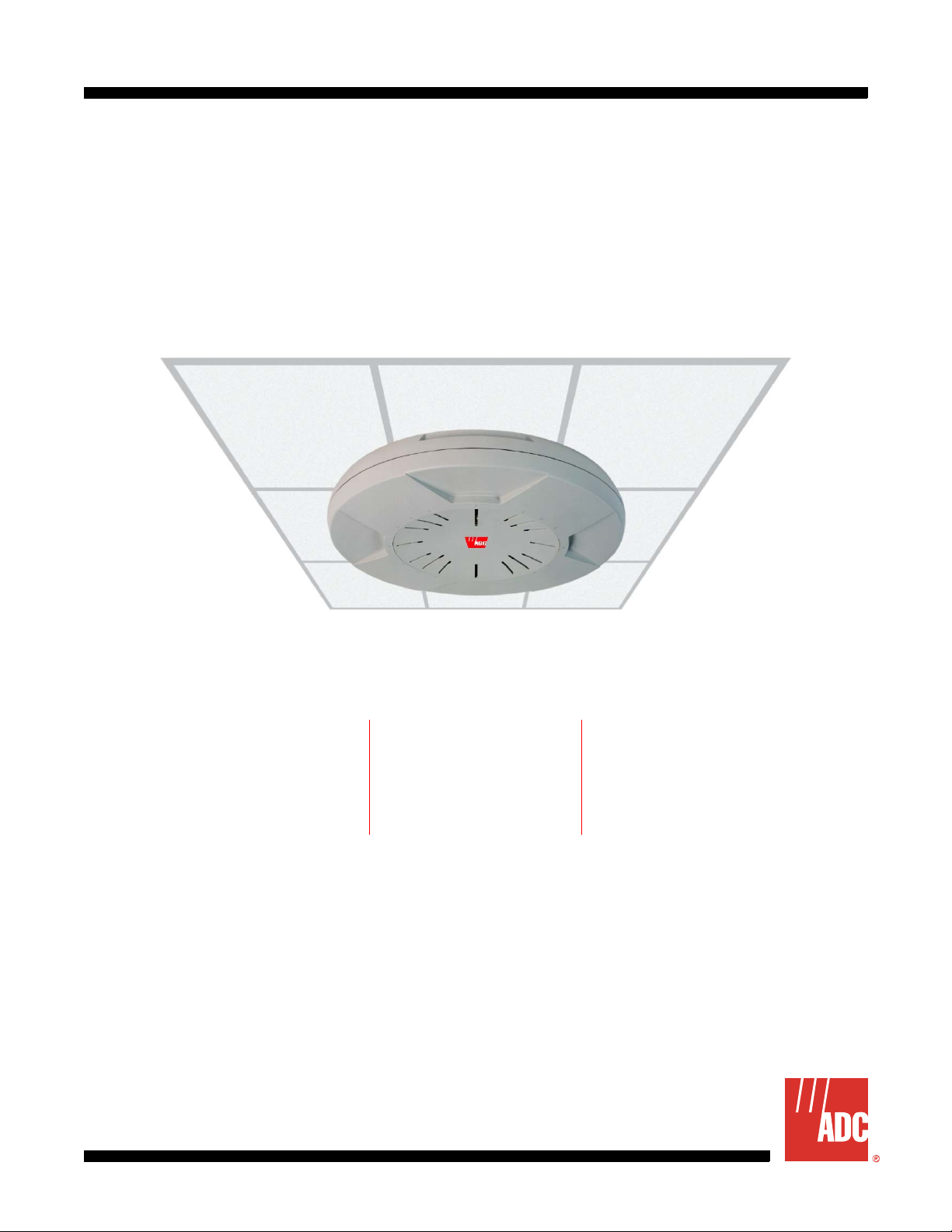
WFX-3900/3700/3500 Wireless LAN Array
User Manual
WFX-3900 Shown
WFX-3900 (16-Port) WFX-3700 (8-Port) WFX-3500 (4-Port)
WFX-3900-16 L11
WFX-3900-16 L21
WFX-3900-16-L12
WFX-3900-16-L22
WFX-3700-8 L1 1
WFX-3700-8 L21
WFX-3700-8 L12
WFX-3700-8 L22
Document Number:
WFX-3500-4 L31
WFX-3500-4 L32
AIWS-UM-4003-01
Page 2

REVISION HISTORY
The Revision History provides a summary of any changes in this manual. Please make sure you are using the
latest revision of this manual.
December 22, 2005
Revision Release Date Revisions Made
01 December 22, 2005 Initial Release
This manual is available online at ADC’s website (www.adc.com/documentationlibrary/) or you can order copies
of the manual by contacting your sales representative. Please ask for d ocument AIWS-UM-4003-01.
Copyright
©2005 ADC Telecommunications, Inc. All righ ts reserved.
Trademark Information
ADC is a register ed tr ademark of ADC Telecommunications, Inc. No right, license, or interest to such trademarks is granted
hereunder, and you agree that no such right, license, or interest shall be asserted by you with respect to such trademark.
Other product names mentioned in this practice are used for identification purposes only and may be trademarks or registered trademarks of their respective companies.
Disclaimer of Liability
Information contained in this document is company private to ADC Telecommunications, Inc., and shall not be modified,
used, copied, reproduced or disclosed in whole or in part without the written cons ent of ADC.
Contents herein are current as of the date of publication. ADC reserves the right to change the contents without prior notice.
In no event shall ADC be liable for any damages resulting from loss of data, loss of use, or loss of profits, and ADC further
disclaims any and all liability for indirect, incidental, special, consequential or other similar damages. This d isclaimer of
liability applies to all products, publications and services during and after the warranty period.
Page 3

Table of Content s
About This Manual ..........................................................................................................xi
Introduction ...............................................................................................................................xi
Audience ...................................................................................................................................xi
Organization ..............................................................................................................................xi
Conventions .............................................................................................................................xii
Safety Warnings .......................................................................................................................xii
Inspecting Your Shipment .......................................................................................................xiii
Chapter 1: Overview ....................................................................................................... 1-1
Product Overview ..................................................................................................................... 1-1
Key Features and Benefits .......................................................................................................1-3
Product Specifications (WFX-3900 and WFX-3700) ................................................................ 1-5
Product Specifications (WFX-3500) ......................................................................................... 1-9
Chapter 2: Installation .................................................................................................... 2-1
Installation Prerequisites .................................................................................................... ......2-1
Planning Your Installation .........................................................................................................2-2
Installation Workflow .............................................................................................................. 2-13
Unpacking the Array ............................................................................................................... 2-13
Installing Your Wireless LAN Array ........................................................................................ 2-14
Powering Up the Wireless LAN Array ....................................................................................2-21
Establishing Communication with the Array ........................................................................... 2-22
Performing the Express Setup Procedure ............................................................................. 2-23
Installing the WFX-3900 Wall Mount Asse mbly ..................................................................... 2-26
Chapter 3: Web Management Interface (WMI) ............................................................. 3-1
An Overview ............................................................................................................................. 3-1
Contents ...................................................................................................................................3-2
Structure ................................................................................................................................... 3-3
Chapter 4: Configuration ............................................................................................... 4-1
Logging In ................................................................................................................................. 4-1
Making Configuration Changes to the Array ...................................... ......................................4-1
Chapter 5: Command-Line Interface ............................................................................. 5-1
Establishing a Secure Shell (SSH) Connection .......................................................................5-1
Basic Commands ..................................................................................................................... 5-2
Command Modes ..................................................................................................................... 5-2
Selecting Interfaces .................................................................................................................. 5-5
Commands ...............................................................................................................................5-5
AIWS-UM-4003-01 iii
Page 4

Table of Contents December 22, 2005
Appendix A: Quick Reference Guide ..........................................................................A-1
Review of WMI Pages ..............................................................................................................A-1
Factory Default Settings ...........................................................................................................A-3
Keyboard Shortcuts ..................................................................................................................A-7
Appendix B: Troubleshooting .....................................................................................B-1
General Hints and Tips .............................................................................................................B-1
Frequently Asked Questions ....................................................................................................B-1
Appendix C: Product Support .....................................................................................C-1
Glossary ......................................................................................................................GL-1
iv AIWS-UM-4003-01
Page 5

List of Figures
Figure 1-1. Wireless Coverage Patterns .............................................................................1-1
Figure 1-2. Remote DC Power Distribution ........................................................................1-2
Figure 1-3. Layout of IAPs (WFX-3900) .............................................................................1-3
Figure 1-4. Antenna Patterns ..............................................................................................1-4
Figure 2-1. Wall Thickness Considerations ............................. ................ ........................... 2-2
Figure 2-2. Unit Placement .................................................................................................2-3
Figure 2-3. Full (Normal) Coverage ....................................................................................2-4
Figure 2-4. Adjusting RF Patterns .......................................................................................2-4
Figure 2-5. Custom Coverage .............................................................................................2-4
Figure 2-6. Calculating the Area of a Circle ........................................................................2-5
Figure 2-7. Sample 802.11a Cells .......................................................................................2-6
Figure 2-8. Transmit Power ................... ..............................................................................2-7
Figure 2-9. Overlapping Cells .............................................................................................2-7
Figure 2-10.Allocating Channels Manually ..........................................................................2-8
Figure 2-11.Deployment Scenario (54 Mbps)—Per Sector .................................................2-8
Figure 2-12.Deployment Scenario (36 Mbps)—Per Sector .................................................2-9
Figure 2-13.Deployment Scenario (18 Mbps)—Per Sector .................................................2-9
Figure 2-14.Port Failover Protection ..................................................................................2-10
Figure 2-15.Switch Failover Protection ..............................................................................2-10
Figure 2-16.Installation Workflow ......................................................................................2-13
Figure 2-17.Array Placement .............................................................................................2-14
Figure 2-18.Attaching the T-Bar Clips ................................................................................2-16
Figure 2-19.Installing the Mounting Plate (WFX-3900 shown) ..........................................2-17
Figure 2-20.Connecting the Cables ...................................................................................2-18
Figure 2-21.Attaching the Unit (WFX-3900) ......................................................................2-19
Figure 2-22.Attaching the Unit (WFX-3500) ......................................................................2-20
Figure 2-23.Securing the Array ..........................................................................................2-20
Figure 2-24.IAP Positions (WFX-3900) .............................................................................2-21
Figure 2-25.LED Locations (WFX-3900) ...........................................................................2-22
Figure 2-26.Network Interface Ports ..................................................................................2-22
Figure 2-27.WMI: Time Zone .............................................................................................2-25
Figure 2-28.Enabling the NTP Feature ..............................................................................2-25
Figure 2-29.Wall Mount—Marking the Holes .....................................................................2-26
Figure 2-30.Installing the Toggle Bolts ........................................................... .................... 2-27
Figure 2-31.Attaching the Wall Mounting Plate .................................................................2-28
Figure 2-32.Mounting the Array on a Wall .........................................................................2-29
Figure 3-1. Web Management Interface .............................................................................3-1
AIWS-UM-4003-01 v
Page 6

List of Figures December 22, 2005
Figure 3-2. WMI: Frames ....................................................................................................3-3
Figure 3-3. WMI: S tatus Bar ................................................................................................3-4
Figure 4-1. WMI: Logging In to the Wireless LAN Array ..................................................... 4-1
Figure 4-2. WMI: Array Status Page ...................................................................................4-2
Figure 4-3. Linked Items .....................................................................................................4-2
Figure 4-4. WMI: Disabled Device (Partial View) ................................................................4-2
Figure 4-5. IAP Cells ...........................................................................................................4-3
Figure 4-6. WMI: Express Setup Page (Part 1) ..................................................................4-4
Figure 4-7. WMI: Express Setup Page (Part 2) ..................................................................4-4
Figure 4-8. WMI: Time Zones .............................................................................................4-7
Figure 4-9. Enabling the NTP Feature ................................................................................4-7
Figure 4-10.WMI: Network Interfaces Page ........................................................................ 4-8
Figure 4-11.WMI: Network Settings Page (Part 1) ..............................................................4-9
Figure 4-12.WMI: Network Settings Page (Part 2) ..............................................................4-9
Figure 4-13.Network Interface Ports ..................................................................................4-10
Figure 4-14.WMI: Network Statistics Page ........................................................................4-12
Figure 4-15.WMI: DHCP Settings Page ............................................................................4-13
Figure 4-16.WMI: DNS Settings Page ...............................................................................4-14
Figure 4-17.WMI: IAP Interfaces Page ..............................................................................4-15
Figure 4-18.WMI: IAP Settings Page .................................................................................4-16
Figure 4-19.WMI: Global Settings Page ............ ................................................................4-18
Figure 4-20.WMI: Global Settings .11a Page ....................................................................4-19
Figure 4-21.Specifying 802.11a Data Rates ............................... ................. .............. ........4-20
Figure 4-22.WMI: Global Settings .11bg Page ..................................................................4-21
Figure 4-23.Specifying 802.11g Data Rates ............................... ................. .............. ........4-21
Figure 4-24.Specifying 802.11b Data Rates ............................... ................. .............. ........4-22
Figure 4-25.WMI: IAP LED Settings Page .........................................................................4-23
Figure 4-26.WMI: St atistics Page ......................................................................................4-24
Figure 4-27.WMI: St atistics for IAP a4 Page (WFX-3700) ................................................4-25
Figure 4-28.WMI: St atistics for All IAPs Page (WFX-3700) ...............................................4-26
Figure 4-29.WMI: SSID Page .................................................................................. ..........4-27
Figure 4-30.WMI: SSID Management Page ......................................................................4-28
Figure 4-31.WMI: Security Page .......................................................................................4-30
Figure 4-32.WMI: Security Management Page .................................................................4-31
Figure 4-33.WMI: Radius Server Page ..............................................................................4-34
Figure 4-34.WMI: Radius User Page .................................................................................4-35
Figure 4-35.WMI: MAC Access List Page .........................................................................4-36
vi AIWS-UM-4003-01
Page 7

December 22, 2005 List of Figures
Figure 4-36.WMI: Admin Management Page ....................................................................4-37
Figure 4-37.WMI: Rogue AP List Page ..................................................................... ........4-38
Figure 4-38.WMI: Rogue Control List Page .......................................................................4-39
Figure 4-39.WMI: St ations Page ........................................................................................4-40
Figure 4-40.WMI: Services Page .......................................................................................4-40
Figure 4-41.WMI: Time Settings Page ...............................................................................4-41
Figure 4-42.WMI: System Log Page .................................................................................4-42
Figure 4-43.WMI: SNMP Page .......................................................................................... 4-43
Figure 4-44.WMI: Array Info Page .....................................................................................4-44
Figure 4-45.WMI: Tools Page ................................................................. ................. ..........4-44
Figure 4-46.WMI: Show Config Page ................................................................................4-45
Figure 4-47.WMI: Event Log Page ....................................................................................4-46
Figure 5-1. Command Line Interface .......................................................... ........................ 5-1
Figure A-1. Disconnecting Power from the Array ................................................................A-1
Figure A-2. Removing the Access Panel Screws ................................................................A-2
Figure A-3. Removing the Access Panel ............................................................................A-3
Figure A-4. Disconnecting the Power Supply and Fan .......................................................A-3
Figure A-5. Reconnecting the Fan and Power Supply ........................................................A-4
Figure A-6. Reinstalling the Access Panel ..........................................................................A-4
Figure A-7. Removing the FLASH Memory Module ............................................................A-5
Figure A-8. Removing the DIMM Memory Module ..............................................................A-6
Figure A-9. Removing the Chassis Cover Nylon Screws ....................................................A-7
Figure A-10.Removing the Chassis Cover ..........................................................................A-7
Figure A-11.Lifting the Integrated Access Point Module ......................................................A-8
Figure A-12.Disconnect the Integrated Access Point Module .............................................A-8
Figure A-13.Installing a New Access Panel (with Power Supply) .......................................A-9
AIWS-UM-4003-01 vii
Page 8

List of Figures December 22, 2005
viii AIWS-UM-4003-01
Page 9

List of Tables
Table 2-1.Serial Connection Settings ..................................................................................2-1
Table 2-2.Recommended Cell Sizes per Data Rate ...........................................................2-5
Table 2-3.Port Failover Protection .....................................................................................2-10
Table 2-4.Deployment Summary .......................................................................................2-12
Table 2-5.Parts and Equipment .........................................................................................2-13
Table B-1.Serial ............................................................................................. ................. .....B-3
Table B-2.Gigabit 1 and Gigabit 2 .......................................................................................B-3
Table B-3.Fast Ethernet .......................................................................................................B-3
Table B-4.Integrated Access Points (IAPs) .........................................................................B-4
Table B-5.DHCP ................................................................................ ..................................B-4
Table B-6.External RADIUS .................................................................................................B-4
Table B-7.Internal RADIUS ..................................................................................................B-5
Table B-8.NTP ........................................................................ .............. .............. .................B-5
Table B-9.Syslog ..................................................................................................................B-5
Table B-10.SNMP ................................................................................................................B-5
Table B-11.Default SSID ......................................................................................................B-6
Table B-12.Encryption ..........................................................................................................B-6
Table B-13.Administrator Account and Password ...............................................................B-6
Table B-14.Management .............................................................................. ........................B-7
AIWS-UM-4003-01 ix
Page 10

List of Tables December 22, 2005
x AIWS-UM-4003-01
Page 11

ABOUT THIS MANUAL
INTRODUCTION
This User’s Guide provides essential information about the ADC® Wireless LAN Array (also referred to throughout
this document as “the Array”).
AUDIENCE
This manual is written for wireless network administrators who will install, configure and manage the Array and
assumes you are familiar with ADC hardware, cabling, electronic circuitry, and wiring practices.
ORGANIZATION
This manual includes the following chapters:
Chapter Description
Chapter 1: Overview Introduces the Wireless LAN Array, including an overview of its
key features and benefits and a detailed listing of the product’s
physical, environmental, and regulatory specifications.
Chapter 2: Installation Defines the prerequisites for installing the Array and provides
instructions to help you complete a successful installation.
Chapter 3: Web Management Interface (WMI) Provides an overview of the Array’s embedded Web
Management Interface (WMI), used for establishing your
network’s configuration settings and wireless operating
parameters.
Chapter 4: Configuration Addresses configuration and management tasks using the
product’s embedded Web Management Interface (WMI). It also
includes a procedure for logging in to the Array with your Web
browser.
Chapter 5: Command-Line Interface Covers configuration and management tasks using the product’s
Command Line Interface (CLI), and includes a procedure for
establishing a Telnet connection to the Array.
Appendix A: Servicing the Array Contains procedures for servicing the Array, including the
removal and reinstallation of major hardware components.
Appendix A: Quick Reference Guide Contains product reference information. Use this chapter to
locate the information you need quickly and efficiently.
Appendix B: Troubleshooting Provides information that can help you resolve technical
difficulties. Before contacting ADC, review all sections in this
chapter and try to determine if your problem resides with the
Array or your network infrastructure.
Appendix C: Product Support Provides contact information for the ADC Technical Support
group.
Glossary Defines terms referred to in this User’s Guide.
AIWS-UM-4003-01 xi
Page 12
About This Manual December 22, 2005
CONVENTIONS
The following style conventions and terminology are used throughout this guide.
Element Meaning
Bold font Text that you must input exactly as shown (e.g., type 1 for card 1), menu buttons
(e.g., ACCEPT SHELF OPTIONS) or menu screen options (e.g., ALARMS screen) that
you must select
Italic font Variables that you must determine before inputting the correct value (e.g., Password )
Monospace font References to screen prompts (e.g., Invalid Password...Try Again:.)
Reader Alert Meaning
Alerts you to supplementary information
IMPORTANT
Alerts you to supplementary information that is essential to the completion of a task
!
Alerts you to possible equipment damage from electrostatic discharge
ATTENTION
CAUTION
WARNING
DANGER
SAFETY WARNINGS
CAUTION
Read all user documentation before powering this device. All ADC interconnected equipment
should be contained indoors. This product is not suitable for outdoor operation. Please verify the
integrity of the system ground prior to installing the equipment. Additionally, verify that the
ambient operating temperature does not exceed 50°C.
Alerts you to possible data loss, service-affecting procedures, or other similar type
problems
Alerts you that failure to take or avoid a specific action might result in hardware damage or
loss of service
Alerts you that failure to take or avoid a specific action might result in personal harm
DANGER
DANGER
CAUTION
Do not operate this device near unshielded blasting caps or in an explosive environment unless
the device has been modified to be especially qualified for such use.
Do not work on this device or connect or disconnect cables during periods of lightning activity.
This product relies on the building’s installation for over current protection. Ensure that a fuse or
circuit breaker no larger than 120 VAC, 15A (U.S.) or 240 VAC, 10A (International) is used on all
current-carrying conductors.
xii AIWS-UM-4003-01
Page 13

December 22, 2005 About This Manual
INSPECTING YOUR SHIPMENT
Upon receipt of the equipment:
• Unpack each container and visually inspect the contents for signs of damage. If the equipment has been damaged in transit, immediately report the extent of damage to the transportation company and to ADC. Order
replacement equipment, if necessary.
• Check the packing list to ensure complete and accurate shipment of each listed item. If the shipment is short
or irregular, contact ADC as described in Appendix C: Product Support on page C-1. If you must store the
equipment for a prolonged period, store the equipment in its original co ntainer.
AIWS-UM-4003-01 xiii
Page 14

About This Manual December 22, 2005
xiv AIWS-UM-40 03-01
Page 15

Chapter
1
OVERVIEW
This chapter introduces the Wireless LAN Array, including an overview of its key features and benefit s, and a
detailed listing of the product’s physical, environmental, techn ology and regulatory specifications. T opics discussed
in this chapter include:
• “Product Overview” on page 1-1
• “Key Features and Benefits” on page 1-3
• “Product S pecifica tions (WFX-3900 and WFX- 3700 )” on page 1-5
• “Product S pecifica tions (WFX-3500) ” on page 1-9
PRODUCT OVERVIEW
The Wireless LAN Array is a high capacity, multi-mode device designed for the Enterprise market, with twice the
range and up to sixteen times the capacity of competitive wireless products.
Wireless LAN Array (WFX-3900/3700/3500)
The Array (regardless of product model) is Wi-Fi® compliant and simultaneously supports 802.11a, 802.11b, and
802.11g clients. Enterprise class features such as VLAN support and multiple SSID capability enable robust
network compatibility and a high level of scalability and system control. The optional Wireless Management
System (WFX-3300) allows global management of hundreds of Arrays from a central location.
Enterprise Class Security
The latest and most effective wireless encryption security standards, including WPA (Wi-Fi Protected Access) with
802.11i AES (Advanced Encryption Standard) are provided with the Array. In addition, the use of an embedded
RADIUS server (or 802.1x with an external RADIUS server) ensures user authentication—multiple Arrays can
authenticate to the optional WFX-3300 ensuring only authorized Wireless LAN Arrays become part of the wireless
network. Rogue AP detection and site monitoring is performed in the background by the Array automatically.
Deployment Flexibility
ADC’s unique multi-radio architecture generates 360 degrees of sectored high-gain 802.11a/b/g coverage that
provides extended range and the highest possible data rates for a large volume of clients. Each sector can be
controlled automatically or manually , creating a pattern of wireless coverage perfectly t ailored to individual customer
needs. For example:
1
outside wall
Figure 1-1. Wireless Coverage Patterns
1. The WFX-3700 and WFX-3500 versions of the Wireless LAN Array deliver a lower capacity than the WFX-3900.
AIWS-UM-4003-01 1-1
Page 16
Chapter 1: Overview December 22, 2005
Figure 1-1 on the previous page depicts the following two scenarios:
• Full pattern coverage – All radios are activated with coverage spanning 360 degrees. If within range, clients
will always receive coverage regardless of their geographic position relative to the Array.
• Partial pattern coverage – If desired, the Array can be deployed close to an exterior wall. In this case, half of all
available radios have been deactivated to prevent redundant signals from “bleeding” beyond the site’ s perimeter
wall. This configuration may also be used in those cases where you want to restrict wireless coverage to
selected areas of the building’s interior.
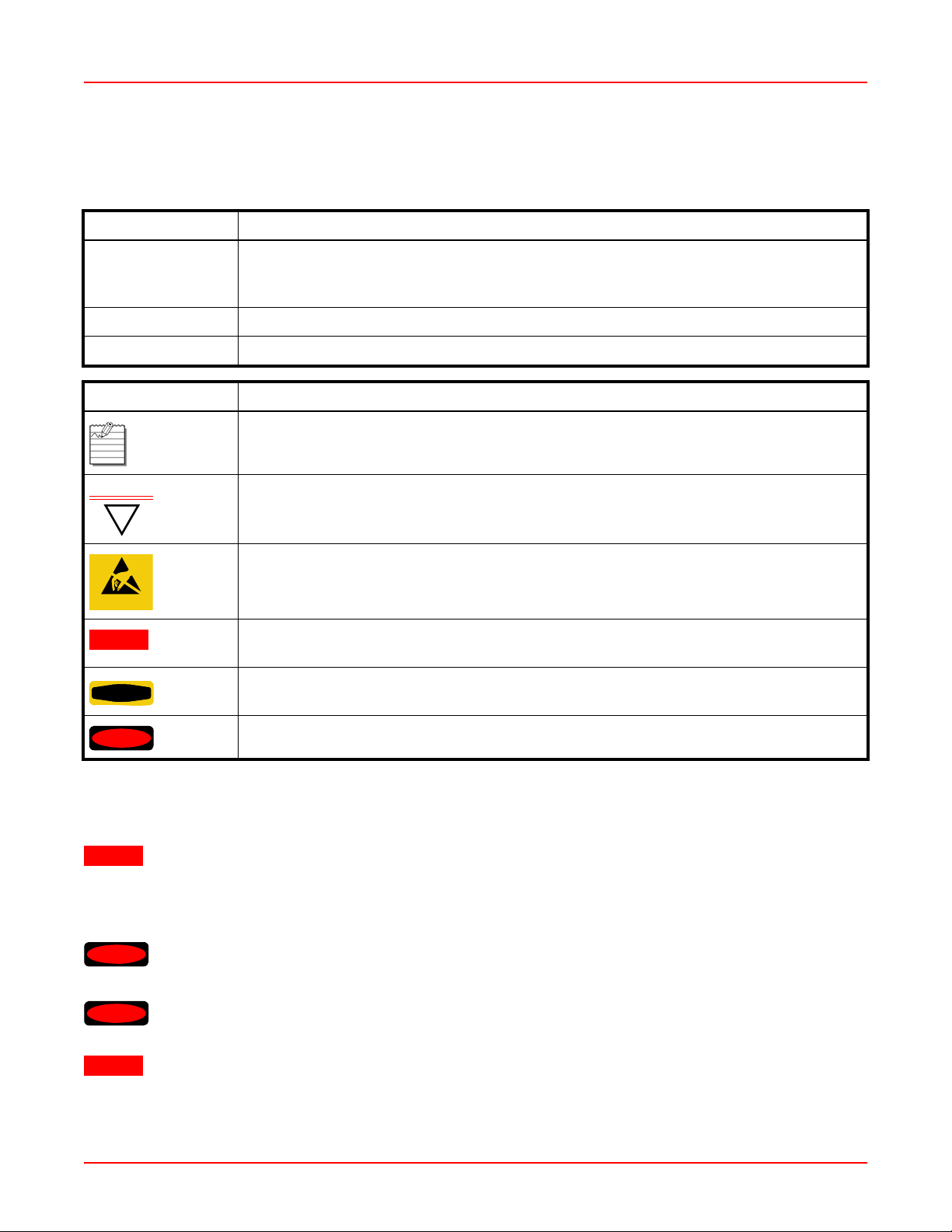
Remote DC Power System (Optional)
The Remote DC Power System (WFX-3100) provides distributed DC power to your Array (DC version)
deployments, eliminating the need to provide an AC power outlet in close proximity to the unit(s). In the following
example (Figure 1-2), DC power is supplied to four Arrays while utilizing only one AC power outlet.
AC Input to WFX-3100
WFX-3100
DC Output to Arrays
Figure 1-2. Remote DC Power Distribution
Enterprise Class Management
The Array can be configured with its default RF settings, or the RF settings can be customized using the Array’s
embedded Web Management Interface (WMI). The WMI enables easy configuration and contr ol from a graphical
console, along with a full compliment of troubleshooting tools, reports and statistics.
In addition, a fully featured Command Line Interface (CLI) of fers IT professionals a familiar management and contro l
environment. SNMP (Simple Network Management Protocol) is also supporte d to allow management from an
SNMP compliant management tool, such as the optional Wireless Management System.
Note: For deployments of more than two Arrays, ADC recommends you use the Wireless Management
System (WFX-3300). The WFX-3300 enables control of large deployments.
1-2 AIWS-UM-4003-01
Page 17

December 22, 2005 Chapter 1: Overview
KEY FEATURES AND BENEFITS
This section describes some of the key product features and the benefits you can expect when deploying the Array
(the WFX-3900 product is highlighted in this section).
High Capacity and High Performance
The WFX-3900 easily handles time-sensitive traffic, such as voice, and can enable wireless connectivity for 1,024
users. The unit includes two Gigabit uplink ports for connection to the wired network. A tot al of sixteen IAPs provides
a maximum wireless capacity of 864 Mbps, which offers ample reserves for the high demands of current and future
applications. Of the sixteen IAPs, twelve operate in the 802.11a mode and four operate in any combination of
802.11a, 802.11b, and 802.11g.
If desired, IAP (radio) abg2 can also be configured in RF monitoring and rogue AP detection mode.
a12
a11
abg4
a1
abg1
a10
a9
a8
abg3
a7
a6
Mode(s) IAP number
Figure 1-3. Layout of IAPs (WFX-3900)
Extended Coverage
One WFX-3900 solution enables you to replace up to sixteen access points (includes one omnidirectional IAP for
monitoring the network). Fifteen IAP radios with integrated directional antennas pro vide increased wir eless range
and enhanced data rates in all directions. With an Array deployed, far fewer access points are needed for your
wireless network. Radio abg2 (see Figure 1-3) can be switched to use an integrated omnidirectional antenna—for
listening only—and can be dedicated to the tasks of site monitoring and rogue AP detection.
a2
a3
a4
abg2 (RF monitoring)
a5
AIWS-UM-4003-01 1-3
Page 18

Chapter 1: Overview December 22, 2005
Array
Array
802.11a (directional) 802.11a/b/g (directional)
Array
802.11a/b/g (omnidirectional)
Figure 1-4. Antenna Patterns
Non-Overlapping Channels
Complete use of non-overlapping channels limits interference and delivers maximum capacity. On the WFX-3900,
all 16 non-overlapping channels are fully utilized across the 5Ghz and 2.4Ghz spectrums (12 across the 5GHz
spectrum and 4 across the 2.4GHz spectrum).
Secure Wireless Access
Multiple layers of authentication and encryption ensure secure data transmissions. The Array is 802.11i compliant
with encryption support for 64 bit and 128 bit WEP, and WPA with TKIP and AES encryption.
Authentication support is provided via 802.1x, including PEAP, EAP-TLS, and EAP-TTLS.
Applications Enablement
QoS (Quality of Service) functionality combined with true switch capabilities enable high density Voice over Wireless
LAN deployments. Compliant with 802.1p and 802.1q st andards.
SDMA Optimization
SDMA (Spatial Division Multiple Access) technology provides full 360° coverage while allowing independent
channel and power output customization. Also supports fast inter-zone handoffs for time-sensitive applications and
roaming support.
Easy Deployment
The Wireless Management System (WFX-3300) offers real time monitoring and management capabilities of the
wireless network—ideal for the Enterprise market. It also allows you to import floor plans to help you plan your
deployment. The Wireless LAN Array chassis has a plenum rated, lockable and tamper resistant case.
1-4 AIWS-UM-4003-01
Page 19

December 22, 2005 Chapter 1: Overview
PRODUCT SPECIFICATIONS (WFX-3900 AND WFX-3700)
Element Specifications
Number of Users Maximum of 64 associated users per radio
1024 users per Array (WFX-3900)
512 users per Array (WFX-3700)
Physical Diameter: 18.65 inches (47.37 cm)
Height: 3.87 inches (9.83 cm)
Weight: 9 lbs (4.08 kg)
Environmental Operating Temperature:
-10°C to 50°C
0% to 90% relative humidity (non-condensing)
Storage Temperature:
-20°C to 60°C
5% to 95% relative humidity (non-condensing)
Maximum Operating Altitude:
2000 meters (6561 feet)
System 825 MHz CPU
128MB RAM, expandable
512MB system flash, expandable
Expansion slot for future options
Electrical Input Power (AC version): 90VAC to 265VAC at 47Hz to 63Hz
Input Power (DC version): 48VDC
Interfaces Serial:
1 x RS232 – RJ45 connector
Ethernet Interfaces:
2 x Gigabit 10/100/1000 Mbps w/failover
1 x Fast Ethernet 10/100 Mbps
Status LEDs:
System status, Ethernet, Radio
AIWS-UM-4003-01 1-5
Page 20

Chapter 1: Overview December 22, 2005
Element Specifications
Management Web-based HTTPS
SNMP v3
CLI via SSHv2 or Telnet
FTP
TFTP
Serial
Proprietary
Wireless Management System
Syslog reporting for alerts/alarms
Networking DHCP client, DHCP server, NTP client
RFC
VLAN Support 802.1Q, P VLAN
Supports up to 16 VLANs
Multiple SSID Support Allows up to 16 separate SSIDs to be defined with map security, VLAN
and QoS settings for each SSID
Performance Client Load Balancing:
Automatic load balancing between system radios
Quality of Service:
802.1P wired traffic prioritization
Wireless packet prioritization
MAP CoS to TCID
Fair queuing of downstream traffic
1-6 AIWS-UM-4003-01
Page 21

December 22, 2005 Chapter 1: Overview
Element Specifications
Security Wireless Security:
WEP 40bit/128bit encryption
WPA with TKIP and AES encryption
Misappropriated APs automatically reset to factory defaults
(requires the Wireless Management System)
Rogue AP detection, with alerts and classification
User and System Authentication:
WPA Pre-Shared Key authentication
Embedded RADIUS Server
802.1x EAP-TLS
802.1x EAP-TTLS
802.1x PEAP
External RADIUS servers
Authentication of Arrays to the Management System (WFX-3300)
AIWS-UM-4003-01 1-7
Page 22

Chapter 1: Overview December 22, 2005
Element Specifications
Wireless Number of Radios:
WFX-3900:
12 x 802.11a radios
4 x 802.11a/b/g radios
WFX-3700:
4 x 802.11a radios
4 x 802.11a/b/g radios
Wireless Standards:
802.11a/b/g and g-only mode
802.11e (draft), 802.11i
Channel Selection:
Manual
Automatic
Frequency Bands:
11a: 5.15-5.25 GHz (UNII 1)
11a: 5.15-5.25 GHz (TELEC)
11a: 5.25-5.35 GHz (UNII 2)
11a: 5.470-5.725 (ETSI)
11a: 5.725-5.825 GHz (UNII 3)
11b/g: 2.412-2.462 GHz (FCC)
11b/g: 2.412-2.472 GHz (ETSI)
11b/g: 2.412-2.484 GHz (TELEC)
Antenna:
Internal 6 dBi sectorized antenna
External RP-TNC connector
Radio Approvals:
FCC (United States)
EN 301.893 (Europe)
Compliance UL / cUL 60950 and EN 60950
FCC Part 15.107 and 15109, Class A
EN 301.489 (Europe)
Warranty One year (hardware), 90 day (software)
1-8 AIWS-UM-4003-01
Page 23

December 22, 2005 Chapter 1: Overview
PRODUCT SPECIFICATIONS (WFX-3500)
Element Specifications
Number of Users Maximum of 64 associated users per radio (256 users per Array).
Recommended number of typical users per Array is 20.
Physical Diameter: 12.58 inches (31.95 cm)
Height: 2.58 inches (6.55 cm)
Weight: 4lbs (1.81 kg)
Environmental Operating Temperature:
-10°C to 50°C
0% to 90% relative humidity (non-condensing)
Storage Temperature:
-20°C to 60°C
5% to 95% relative humidity (non-condensing)
Maximum Operating Altitude:
2000 meters (6561 feet)
System 825 MHz CPU
128MB RAM, expandable
512MB system flash, expandable
Expansion slot for future options
Electrical Input Power (AC version): 90VAC to 265VAC at 47Hz to 63Hz
Input Power (DC version): 48VDC
Interfaces Serial:
1 x RS232 – RJ45 connector
Ethernet Interfaces:
1 x Gigabit 10/100/1000 Mbps w/failover
Status LEDs:
System status, Ethernet, Radio
AIWS-UM-4003-01 1-9
Page 24

Chapter 1: Overview December 22, 2005
Element Specifications
Management Web-based HTTPS
SNMP v3
CLI via SSHv2 or Telnet
FTP
TFTP
Serial
Proprietary
Wireless Management System
Syslog reporting for alerts/alarms
Networking DHCP client, DHCP server, NTP client
RFC
VLAN Support 802.1Q, P VLAN
Supports up to 16 VLANs
Multiple SSID Support Allows up to 16 separate SSIDs to be defined with map security, VLAN
and QoS settings for each SSID
Performance Client Load Balancing
Automatic load balancing between system radios
Quality of Service:
802.1P wired traffic prioritization
Wireless packet prioritization
MAP CoS to TCID
Fair queuing of downstream traffic
1-10 AIWS-UM-4003-01
Page 25

December 22, 2005 Chapter 1: Overview
Element Specifications
Security Wireless Security:
WEP 40bit/128bit encryption
WPA with TKIP and AES encryption
Misappropriated APs automatically reset to factory defaults
(requires the Wireless Management System)
Rogue AP detection, with alerts and classification
User and System Authentication:
WPA Pre-Shared Key authentication
Embedded RADIUS Server
802.1x EAP-TLS
802.1x EAP-TTLS
802.1x PEAP
External RADIUS servers
Authentication of Arrays to the Management System (WFX-3300)
AIWS-UM-4003-01 1-11
Page 26

Chapter 1: Overview December 22, 2005
Element Specifications
Wireless Number of Radios:
4 x 802.11a/b/g radios
Wireless Standards:
802.11a/b/g and g-only mode
802.11e (draft), 802.11i
Channel Selection:
Manual
Automatic
Frequency Bands:
11a: 5.15-5.25 GHz (UNII 1)
11a: 5.15-5.25 GHz (TELEC)
11a: 5.25-5.35 GHz (UNII 2)
11a: 5.470-5.725 (ETSI)
11a: 5.725-5.825 GHz (UNII 3)
11b/g: 2.412-2.462 GHz (FCC)
11b/g: 2.412-2.472 GHz (ETSI)
11b/g: 2.412-2.484 GHz (TELEC)
Antenna:
4 internal 3 dBi 180° 802.11b/g sectorized antennas
1 internal 2 dBi 360° omni-directional antenna
External RP-TNC connector
Radio Approvals:
FCC (United States)
EN 301.893 (Europe)
Compliance UL / cUL 60950 and EN 60950
FCC Part 15.107 and 15109, Class A
EN 301.489 (Europe)
Warranty One year (hardware), 90 day (software)
1-12 AIWS-UM-4003-01
Page 27

Chapter
INSTALLATION
This chapter defines the prerequisites for installing the Array and pro vides in struction s to help you complete a
successful installation. Topics addressed in this chapter include:
• “Installation Prerequisites” on page 2-1
• “Planning Your Installation” on page 2-2
• “Installation Workflow” on pa ge 2-13
• “Unpacking the Array” on page 2-13
• “Installing Your Wireless LAN Array” on page 2-14
• “Powering Up the Wireless LAN Array” on page 2-21
• “Establishing Communication with the Array” on page 2-22
• “Performing the Express Setup Procedure” on page 2-23
• “Installing the WFX-3900 Wall Mount Assembly” on page 2-26
INSTALLATI ON PREREQUISITES
Your Array deployment requires hardware and services in the host wired/wireless network, including:
• Dedicated AC power outlet – Unless you are using the Remote DC Power System (WFX-3100) with the DC
version of the Array, you need a dedicated power outlet to supply AC power to each unit deployed at the site. If
you are using the optional WFX-3100, then DC power is supplied to all units and only one AC outlet is required
for the WFX-3100.
• Ethernet port (read notes) – You need at least one 10/100/1000 BaseT port to est ablish wired Gigabit Ethernet
connectivity (via the product’s Gigabit 1 or Gigabit 2 port) and one 10/100 BaseT port (if desired) for product
management.
2
IMPORTANT
!
IMPORTANT
!
• Secure Shell (SSH) utilit y – To establish secure remote command line access to the Array, you need a Se cure
Shell (SSH) utility, such as PuTTY.
• Secure Web browser – Either Internet Explorer (version 6.0 or higher), Netscape Navigator (version 7.0 or
higher), or Mozilla Firefox (version 1.01 or higher) and it must be available on the same subnet as the Array. A
secure Web browser is required for Web-based management of the Array.
• Serial connection capability – To connect directly to the console port on the Array, your co mputer must be
equipped with a male 9-pin serial port and terminal emulation software (for example, HyperTerminal). Use the
following settings (Table 2-1) when establishing a seri al connection:
The Array’s Ethernet ports should be plugged into an Ethernet switch, not an Ethernet hub; if a
hub is used, we recommend you connect only one Ethernet port.
The Gigabit1 Ethernet interface is the primary port for both data and management traffic. If a
single Ethernet connection is used, it must be connected to the Gigabit1 Ethernet interface.
The 10/100 Ethernet Port can be used for managing the Array, and will only bridge manage me nt
traffic. See also, “Port Failover Protection” on page 2-10.
AIWS-UM-4003-01 2-1
Page 28

Chapter 2: Installation December 22, 2005
Table 2-1. Serial Connection Settings
Bits per second 115,200
Data bits 8
Parity None
Stop bits 1
Flow control None
Optional Network Components
The following network components are optional.
• DHCP server – To distribute IP addresses and ancillary information to your Array.
• Wireless Management System (WFX-3300) – The optional WFX-3300 offers powerful management features
for small or large Array deployments.
• Remote DC Power System (WFX-3100) – The optional WFX-3100 provides distributed DC power to multiple
Arrays, eliminating the need to run dedicated AC power to each unit and facilitating backup power when connected via a UPS.
• External RADIUS server – Although your Array comes with an embedded RADIUS server, for 802.1x authentication in large deployments you may want to add an external RADIUS server.
Client Requirements
The Array should only be used with Wi-Fi certified client devices.
PLANNING YOUR INSTALLATION
This section provides guidelines and examples to help you plan your Array deployment to achieve the best overall
coverage and performance. We recommend you conduct a site survey to determine the best location and settings
for each Array you install.
General Deployment Considerations
The Array’s unique multi-radio architecture generate s 360 degree s of sectored high-gain 802.11a/b/g coverage that
provides extended range. However, the number, thickness and location of walls, ceilings or other objects that th e
wireless signals must pass through may affect the range. Typical ranges vary depending on the types of materials
and background RF (radio frequency) noise at your location. To maximize wireless range, fo llo w these basic
guidelines:
1. Keep the number of walls and ceilings between the Array and your receiving devices to a minimum—each
wall or ceiling can reduce the wireless range from between 3 and 90 feet (1 to 30 meters). Position your
devices so that the number of walls or ceilings is minimized.
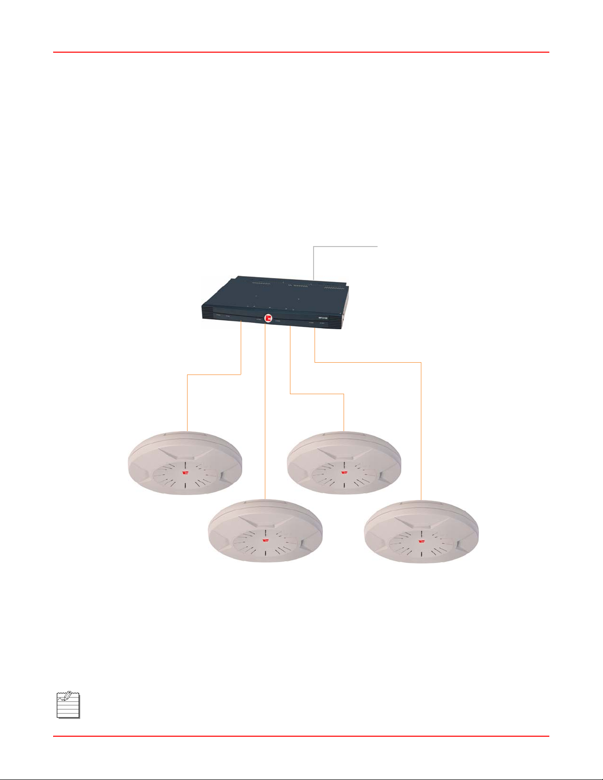
2. Be aware of the direct line between each device. For example, a wall that is 1.5 feet thick (half a meter) at
90° is actually almost 3 feet thick (or 1 mete r) when viewe d at a 4 5° angle. At an acute 2° degr ee angle the
same wall is over 42 feet (or 14 meters) thick! For best reception, try to ensure that your wireless devices
are positioned so that signals will travel straight through a wall or ceiling.
2-2 AIWS-UM-4003-01
Page 29
December 22, 2005 Chapter 2: Installation
90° 45°
< 3 feet
1.5 feet
Figure 2-1. Wall Thickness Considerations
3. Building materials can make all the difference. For example, solid metal doors or aluminum wall studs may
adversely effect wireless signals. Try to position wireless client devices so that the signal passes through
drywall (between studs) or open doorways and not other materials.
Coverage and Capacity Planning
This section considers coverage and capacity for your deployment(s), including placement o ptions, RF patterns and
cell sizes, area calculations, roaming considerations, and channel allocations.
Placement
Use the following guidelines when considering placement options:
1. The best placement option for the Array is ceiling-mounted within an open plan environment (cubicles rather
than fixed walls).
2. Keep the Array away from electrical device s or appliances that generate RF noise. Because the Array is
generally mounted on ceilings, be aware of its position relative to lighting (especially fluorescent lighting)—
we recommend maintaining a distance of at least 3 to 6 feet (or 1 to 2 meters).
3. If using multiple Arrays at the same location, we recommend maintaining a distance of at least 100 feet
between units.
2°
> 42 feet
≥ 100 ft
≥ 100 ft
≥ 100 ft
Figure 2-2. Unit Placement
AIWS-UM-4003-01 2-3
Page 30

Chapter 2: Installation December 22, 2005
RF Patterns
The Array allows you to control—automatically or manually—the pattern of wireless coverage that best suits your
deployment needs. You can choose to operate with full coverage, half coverage, or custom coverage (by enabling
or disabling individual sectors).
Full (Normal) Coverage
In normal operation (see Figure 2-3), the Array provides a full 360 degrees of coverage.
Figure 2-3. Full (Normal) Coverage
Half Coverage
If installing a unit close to an exterior wall, you can deactivate half of the radios to preve nt red unda nt sign als fr om
“bleeding” beyond the wall and extending service into public areas. The same principle applies if you want to restrict
service to an adjacent room within the site.
outside wall
Figure 2-4. Adjusting RF Patterns
2-4 AIWS-UM-4003-01
Page 31

December 22, 2005 Chapter 2: Installation
Custom Coverage
Where there are highly reflective objects in close proximity to the Array, you can turn off specific radios to avoid
interference and feedback.
reflective
object
Figure 2-5. Custom Coverage
Calculating Areas
Before we discuss cell sizes, it is useful to know how to calculate the area of a circle (because the Array radiates a
full 360 degrees). The area of a circle is equal to pi (p) times the square of the radius, where pi is equal to 3.14. The
following graphic calculates the area of a circle with a radius of 20 feet.
3.14 x 202 = 1,256 sq ft
20 ft
Figure 2-6. Calculating the Area of a Circle
Capacity and Cell Sizes
Cell sizes should be calculated based on the number of users, the applications being us ed (fo r example, d at a/video/
voice), and the number of Arrays available at the location. The capacity of a cell is defined as the minimum data rate
desired for each sector multiplied by the total number of sectors being used.
The following chart (Table 2-2) shows the maximum recommended cell sizes for each data rate.
Table 2-2. Recommended Cell Sizes per Data Rate
Desired Data
Rate (Mbps)
Radius (feet) Area (sq. feet) Radius (feet) Area (sq. feet)
11a Cell Size 11b/g Cell Size
54 100 31,400 104 33,962
48 185 107,466 183 105,155
36 247 191,568 260 212,264
24 278 242,672 283 251,479
18 309 299,810 338 358,726
12 339 360,852 364 416,037
AIWS-UM-4003-01 2-5
Page 32

Chapter 2: Installation December 22, 2005
Desired Data
Rate (Mbps)
9 371 432,193 374 439,211
6 402 507,437 390 477,594
11 0 0 416 543,396
5.5 0 0 437 649,295
2 0 0 458 658,659
1 0 0 468 687,735
Sample 802.11a Cells
The following 802.11a sample cells (Figure 2-7) illustrate the coverage area and minimum throughput you can
expect (per sector) based on the size of each cell. Notice how the throughput increases as the cell size decreases,
and vice versa.
Radius (feet) Area (sq. feet) Radius (feet) Area (sq. feet)
11a Cell Size 11b/g Cell Size
68 ft
14,520 sq ft
54 Mbps per sector
165 ft
98 ft
30,157 sq ft
36 Mbps per sector
85,487 sq ft
18 Mbps per sector
Figure 2-7. Sample 802.11a Cells
2-6 AIWS-UM-4003-01
Page 33

December 22, 2005 Chapter 2: Installation
Fine T uning Cell Sizes
Adjusting the transmit power allows you to fine tune cell sizes. There are three settings—Large, Medium, or Small
(the default is Large). If you are installing many units in close proximity to each other, reduce the transmit power to
avoid excessive interference with other Arrays or installed APs. (See also, “IAP Settings” on page 4-16.)
Small
Medium
Large
Figure 2-8. Transmit Power
Roaming Considerations
Cells should overlap approximately 10 - 15% to accommodate client roaming.
ROAMING
10 - 15% overlap
Figure 2-9. Overlapping Cells
Allocating Channels
Because the Array is a multi-channel device, allocating the best channels to radios is import ant if p eak performance
is to be maintained.
Automatic Channel Selection
We recommend that you allow the Array to make intelligent channel allocation decisions automatically. In the
automatic mode, channels are allocated dynamically, driven by changes in the environment.
AIWS-UM-4003-01 2-7
Page 34

Chapter 2: Installation December 22, 2005
Manual Channel Selection
You can manually assign channels on a per radio basis, though manual selection is not recommended or
necessary.
Note: To avoid co-channel interference, do not select adjacent channels for radios that are physically next
to each other.
Maintain channel separation
Figure 2-10. Allocating Channels Manually
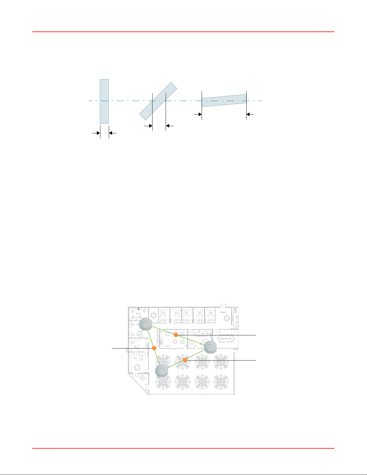
Deployment Examples
The following examples employ 802.11a cells, each offering minimum throughputs of 54 Mbps, 36 Mbps, and 18
Mbps per sector respectively, and assume a floor plan covering a total are a of about 60,000 square fe et.
Figure 2-11. Deployment Scenario (54 Mbps)—Per Sector
2-8 AIWS-UM-4003-01
Page 35

December 22, 2005 Chapter 2: Installation
Figure 2-12. Deployment Scenario (36 Mbps)—Per Sector
Figure 2-13. Deployment Scenario (18 Mbps)—Per Sector
Failover Planning
This section discusses failover protection at the unit and port levels.
AIWS-UM-4003-01 2-9
Page 36

Chapter 2: Installation December 22, 2005
Port Failover Protection
To ensure that service is continued in the event of a port failure, you can utilize the Gigabit 1 and Gigabit 2 ports
simultaneously.
Multiple port connections
Ethernet switch
Figure 2-14. Port Failover Protection
In addition, the Array has full failover protection between the Gigabit 1 and Gigabit 2 Etherne t ports (see T able 2-3).
T ab le 2-3 . Port Failover Prot ect ion
Interface Bridges data? Bridges mgmt traffic? Fails over to: IP address
Fast Ethernet No Yes None DHCP or static
Gigabit 1 Yes Yes Gigabit 2 DHCP or static
Gigabit 2 Yes Yes Gigabit 1 Assumes the IP
address of Gigabit 1
Switch Failover Protection
To ensure that service is continued in the event of a switch failure, you can connect Arrays to more than one
Ethernet switch (not a hub).
Ethernet connections
Ethernet switch
Figure 2-15. Switch Failover Protection
Note: Gigabit Ethernet connections must be on the same subnet.
Backup switch
2-10 AIWS-UM-4003-01
Page 37

December 22, 2005 Chapter 2: Installation
Power Planning
This section discusses the AC and DC power options.
AC Power
The AC power option requires a direct connection between the Array and a dedicated AC power outlet. The power
cord is provided with the unit.
Remote Distributed DC Power
To deliver DC power to the Array, you must have the optional Remote DC Power System (WFX-3100) and an Array
that supports DC power—see Figure 1-2 on page 1-2. The WFX-3100 provides DC powe r to multiple Arrays from a
single source, and requires only one AC power outlet.
Depending on the type of cable used, Arrays can be located up to 1,000 feet from the WFX-3100. In addition, the
WFX-3100 can be plugged into a UPS to prevent power failure to all Arrays in the network.
Note: When using CA T5 ca ble, DC power can be provided up to a dist ance of 300 feet.
Security Planning
This section offers some useful guidelines for defining your preferred encryption and authentication method. For
additional information, go to the Security section of “Frequently Asked Questions” on page B-1.
Wireless Encryption
Encryption ensures that no user can decipher another user’s data transmitted over the airwaves. There are three
encryption options available to you, including:
• WEP-40bit or WEP-128bit – Because WEP is vulnerable to cracks, we recommend that you only use this for
legacy devices that cannot support a stronger encryption type.
• Wi-Fi Protected Access – This is much more secure than WEP and uses TKIP for encryption.
• Wi-Fi Protected Access with AES – This is government-grade encryption—available on most new client
adapters—and uses the AES–CCM encryption mode (Advanced Encryption Standard–Counter Mode).
Authentication
Authentication ensures users are who they say they are, and occurs when users attempt to join the wireless network
and periodically there after. The following authentication methods are available with the WFX-3900:
• RADIUS 802.1x – 802.1x uses a remote RADIUS server to authenticate large numbers of clients, and can handle different authentication methods (EAP-TLS, EAP-TTLS, or EAP-PEAP).
• Internal RADIUS server – Includes all the core functi onality of a full RADIUS server built into the Array. Recommended for smaller numbers of users (about 100 or less).
• Pre-Shared Key – Uses a pass-phrase or key that is manually distributed to all authorized users. The same
passphrase is given to client devices and entered into each Array.
• MAC Access Control Lists (ACLs) – MAC access control lists provide a list of client adapter MAC addresses
that are allowed or denied access to the wireless network, and can be used in addition to any of the above
authentication methods. ACLs are good for embedded devices, like printers and bar-code scanners (though
MAC addresses can be spoofed). The Array supports 512 ACL entries.
AIWS-UM-4003-01 2-11
Page 38

Chapter 2: Installation December 22, 2005
Network Management Planning
Network management can be performed using any of the following methods:
• Command Line Interface, using an SSH (Secure Shell) utility, like PuTTY.
• Web-based management, using the Array’ s embed ded Web Management Interface (WMI). This method
provides configuration and basic monitoring tools, and is good for small de ployments (one or two units).
• Web-based management, using the optional Wireless Management System (WFX-3300). The WFX-3300 is
used for managing large Array deployments from a centralized Web-based interface and offers the following
features:
– Layer 3 appliance
– Globally manage large numbers of Arrays
– Seamless view of the entire wireless network
– Easily configure large numbers of Arrays
– Rogue AP monitoring
– Easily manage system-wide firmware updates
– Monitor performance and trends
– Aggregation of alerts and alarms
Deployment Summary
Table 2-4 summarizes your deployment options for small and large deployments.
Table 2-4. Deployment Summary
Number of Arrays
Function
Power AC
DC (with WFX-3100)
Failover Recommended Highly recommended
VLANs Optional Optional use
Encryption WPA with TKIP (recommended)
PSK or 802.1x
Authentication Internal RADIUS server
Pre-Shared Key
Management Internal WMI
Internal CLI
WFX-3300
One or Two Three or More
AC
DC (with WFX-3100)
UPS backup (recommended)
Can be used to put all APs on
one VLAN or map to existing
VLAN scheme
WPA with AES (recommended)
802.1x keying
External RADIUS server
WFX-3300
2-12 AIWS-UM-4003-01
Page 39

December 22, 2005 Chapter 2: Installation
INSTALLATI ON WORKFLOW
The following workflow (Figure 2-16) illustrates the steps that are required to install and configure your Array
successfully. Review this flowchart before attempting to install the unit on a customer’s network.
Determine the number of Arrays needed
Choose the location(s) for your Array(s).
AC DC
Run AC power and Ethernet cables Run DC power and Ethernet cables
Install the mounting plate
Connect the cables and turn on the power
Verify that the Ethernet link and radio LEDs are function in g cor re ct ly
Perform the Express Setup procedure
Figure 2-16. Installation Workflow
AC or DC
power?
UNPACKING THE ARRAY
When you unpack your Array, you will find the following items in the carton:
Table 2-5. Parts and Equipment
Item Quantity
Wireless LAN Array 1
AC power cord 1
Console cable 1
Mounting plate 1
Mounting screws 4
Tile grid mounting clamps 4
AIWS-UM-4003-01 2-13
Page 40

Chapter 2: Installation December 22, 2005
CORRECT
ON
ON
Item Quantity
Clamp nuts 4
Mounting template 1
CD-ROM containing:
This User’s Guide in PDF format
End User License Agreement (EULA)
README file
Quick Install Guide 1
Registration Card 1
1
INSTALLI NG YOUR W IRELESS LAN ARRAY
This section provides instructions for installing your Wireless LAN Array.
Choosing a Location
Based on coverage, capacity and deployment examples discussed earlier in this chapter , cho ose a location fo r the
Array that will provide the best results for your needs. The Array was designed to be mounted on a ceiling where the
unit is unobtrusive and wireless transmissions can travel unimpeded th roughout open plan areas. Choose a location
that is central to your users (see Figure 2-17 for correct placement).
WRONG
Figure 2-17. Array Placement
Wiring Considerations
Unless you are using the Remote DC Power System (WFX-3100) with the DC version of the Array, an AC power
outlet must be available to the Array (an AC power cord is provided with each unit). If you are using the WFX-3100
to distribute DC power to multiple Arrays, go to “Remote DC Power System (Optional)” on page 1-2.
WRONG
2-14 AIWS-UM-4003-01
Page 41

December 22, 2005 Chapter 2: Installation
Once you have determined the best location for your Array, you must run cables to the location for the following
services:
•Power:
– Dedicated AC power
– DC power (if using the WFX-3100)
•Network:
– Gigabit 1
– Gigabit 2 (optional, not available on the WFX-3500)
– Fast Ethernet (optional, not available on the WFX-3500)
– Serial cable
Important Notes About Network Connections
Read the following notes before making any network connections.
IMPORTANT
!
IMPORTANT
!
Mounting the Unit
Most offices have drop-down acoustical ceiling tiles set into a st andard grid. The Arr ay has been designed to enable
mounting to a tiled ceiling via a mounting plate and clamps that attach to the grid. Once the mounting plate is
attached, the Array simply rotates onto the plate (similar to a smoke detector). Once the unit is mounted it can be
removed and re-attached easily, without the need for tools or modifications to the original installation.
This section assumes that you are mounting the Array to a tiled ceilin g. If your ceiling is not tiled, the mounting plate
can be attached directly to the ceiling with the screws and anchors provided (without using the tile grid mounting
clamps).
The Array’s Ethernet ports should be plugged into an Etherne t switch, not an Ethe rnet hub—if a
hub is used, we recommend that you connect only one Ethernet port.
The Gigabit1 Ethernet interface is the primary port for both data and management traffic. If a
single Ethernet connection is used, it must be connected to the Gigabit1 Ethernet interface.
The 10/100 Ethernet Port can be used for managing the Array, and will only bridge manage me nt
traffic. See also, “Port Failover Protection” on page 2-10.
Note: When the unit’s IP address is unknown or a network connection has not been established, the serial
cable is used for connecting directly with the Command Line Interface (CLI) via HyperTerminal. When a
network connection is established, the Array can be managed from any of the available network
connections, either Fast Ethernet, Gigabit 1 or Gigabit 2.
AIWS-UM-4003-01 2-15
Page 42

Chapter 2: Installation December 22, 2005
Attaching the T-Bar Clips
The T-bar clips are used to create four mounting points on the ceiling tile grid for the Array mounting plate. Use the
mounting template (provided) to find the correct location for all four clamps. To attach the clamps, simply twist the
clamps onto the grid and tighten the screw post with a screwdriver.
T-bar clips (4 places)
Tighten the screw post
Ceiling tile grid
Template
Figure 2-18. Attaching the T-Bar Clips
2-16 AIWS-UM-4003-01
Page 43

December 22, 2005 Chapter 2: Installation
Installing the Mounting Plate
If necessary , orient the mounting plate (see “Att aching the T-Bar Clips” on page 2-16) and locate the plate on the
four screw posts. Secure the mounting plate to the four clamps using the nuts provided. Once the mounting plate is
secured, cut an access hole in the ceiling tile for the cables.
Tile grid
Mounting Plate
Cut an access hole here
Figure 2-19. Installing the Mounting Plate (WFX-3900 shown)
AIWS-UM-4003-01 2-17
Page 44

Chapter 2: Installation December 22, 2005
Connecting the Cables
Feed the power and Ethernet cables through the access hole in the tile and the mounting plate (WFX-3900), then
connect the cables to the unit. See also “Wiring Considerations” on page 2-14.
Figure 2-20. Connecting the Cables
When the cables are connected, turn on the power switch—before attaching the unit to the mounting plate (next
step). Verify that the Ethernet link LED light s and the LED boot sequenc e begins. The radio LEDs on the front of the
unit will illuminate in rotation, indicating that the Array software is loading and the unit is functioning correctly.
2-18 AIWS-UM-4003-01
Page 45

December 22, 2005 Chapter 2: Installation
Attaching the Array to the Mounting Plate (WFX-3900)
Align the port recess on the Array with the access hole in the mounting plate, then connect the Array with the lugs on
the mounting plate (4 places) and turn the Array clockwise to lock the unit into place (similar to a smoke detector).
Figure 2-21. Attaching the Unit (WFX-3900)
AIWS-UM-4003-01 2-19
Page 46

Chapter 2: Installation December 22, 2005
Attaching the Array to the Mounting Plate (WFX-3500)
Align the WFX-3500 Wireless LAN Array with the key post on the mounting plate, then turn the Array to the right to
lock the unit into place at the 4 lugs—similar to a smoke detector.
Key post
Lug
Alignment hole
Figure 2-22. Attaching the Unit (WFX-3500)
Securing the Array
For added security, there is a locking bracket incorporated into the mounting plate, which will accept a small
luggage-style padlock (if desired). There is also a Kensington lock slot located near the Ethernet ports. In addition,
the mounting plate incorporates a positive locking tab that prevents the unit from being inadvertently released.
Locking bracket
Figure 2-23. Securing the Array
Now that the Array is physically installed, you must run the Express Setup procedure from the unit’s Web
Management Interface to enable the radios and establish initial system configuration settings. Go to “Powering Up
the Wireless LAN Array” on page 2-21.
2-20 AIWS-UM-4003-01
Page 47

December 22, 2005 Chapter 2: Installation
Dismounting the Array
To dismount the Array, place your fingers so as to increase the space between the Array and the mounting plate at
the positions indicated by the decals on the mounting plate—these are aligned with IAPs (radios) abg1 and abg3, as
indicated on the clock-face of the Array.
a12
a11
abg4
a1
abg1
a10
a9
a8
abg3
a7
a6
Figure 2-24. IAP Positions (WFX-3900)
a5
a2
a3
a4
abg2
POWERING UP THE WIRELESS LAN ARRAY
When powering up, the Array follows a specific sequence of LED patterns showing the boot progress, and following
a successful boot will provide extensive status information. The normal boot sequence is as follows:
1. The green status LED will light first, showing a steady flashing while the unit boots. In the event of a boot
failure, this LED will change to flashing red.
2. The Ethernet Link/Activity LEDs on the underside of the Array will light for those ports connected to the
network.
3. All IAP radio LEDs will light simultaneously.
4. While the Array is booting, a sequential LED pattern will cycle through all the radio LEDs.
5. When the Array completes boot, the status LED will show a steady green, and all radio lights will show the
current state of those radios.
AIWS-UM-4003-01 2-21
Page 48

Chapter 2: Installation December 22, 2005
Ethernet Activity
LEDs
Status LED
IAP LEDs (x16)
Figure 2-25. LED Locations (WFX-3900)
Once the unit is fully booted, the default IAP LED display will be as follows:
• IAP radio LEDs that are enabled will show a steady orange for 802.11a radios, or green for 802.11b/g radios.
• Once a client associates with an individual IAP, that LED will show a slow flash (heartbeat) pattern.
• When data is transmitted or received by an IAP, that IAP’s LED will flash. The rate of flashing changes with the
number of packets sent or received per second—the LED will flash more quickly with a greater number of packets per second and more slowly with lower numbers of packets per second.
These settings may be altered or disabled entirely for diagnostic purposes or for personal preference. Changes are
made via the Array’s Command Line Interface or the Web Management Interface—refer to “IAP LED Settings” on
page 4-24 for details.
ESTABLISHING COMMUNI CATI ON WITH THE ARRAY
The Array can be configured through the Command Line Interface (CLI) or the graphical Web Management
Interface (WMI). You can use the CLI via the serial management port, the Fast Ether net port, or either of the Gig abit
Ethernet ports. You can use the WMI via any of the Array’s Ethernet ports.
Serial
Fast Ethernet
Gigabit 1
Gigabit 2
Figure 2-26. Network Interface Ports
Using the Serial Port
If using the serial port to make your connection, use serial settings of 8 bits, no parity, 1 stop bit (8N1) and a speed
setting of 115200 baud. Use the communication package of your choice.
2-22 AIWS-UM-4003-01
Page 49

December 22, 2005 Chapter 2: Installation
Using the Ethernet Ports
If the Array is booted and does not receive DHCP addresses on either the Fast Ethernet or Gigabit Ethernet ports,
the Fast Ethernet port will default to an IP address of 10.0.0.1 and both Gigabit Ethernet ports will default to 10.0.1.1
and 10.0.2.1 respectively . If th e Array is connected to a ne twork that provides DHCP addresses, the IP addr ess can
be determined by the following two methods:
1. Examine the DHCP tables on the server and find the addresses assigned to the Array (MAC addresses
begin with 000F7D).
2. Query the Array using the CLI via the serial port. Use the show ethernet command to view the IP
addresses assigned to each port.
Logging In
When logging in to the Array, use the default user name and password—the default user name is admin, and the
default password is admin.
PERFORMING THE EXPRESS SETUP PROCEDURE
The Express Setup procedure allows you to establish global configuration settings that will enable basic Array
functionality. Any changes you make on this page will affect all radios. When finished, click on the Apply button to
apply the new settings to this session, then click on the Save button to save your changes.
Procedure for Performing an Express Setup
Step Action
1 Host Name: Specify a unique host name for this Array. The host name is used to identify the Array on the
network. Use a name that will be meaningful within your network environment, up to 64 alphanumeric
characters.
2 Location Information: Enter a brief but meaningful description that accurately defines the physical
location of the Array. In an environment where multiple units are installed, clear definitions for their
locations are important if you want to identify a specific unit.
3 Admin Contact: Enter the name and contact information of the person who is responsible for
administering the Array at the designated location.
4 Admin Email: Enter the email address of the admin contact you entered in Step 3.
5 Admin Phone: Enter the telephone number of the admin contact you entered in Step 3.
6 Enable/Configure All IAPs: Click on the Execute button to enable and auto configure all IAPs (a
message displays the countdown time—in seconds—to complete the auto-configuration task).
AIWS-UM-4003-01 2-23
Page 50

Chapter 2: Installation December 22, 2005
Step Action
7 Configure the Fast Ethernet (10/100 Megabit), Gigabit 1 and Gigabit 2 network interfaces. The fields for
each of these interfaces are the same, an d inc lud e:
• Enable Interface: Choose Yes to enable this network interface, or choose No to disable the interface.
• Allow Management on Interface: Choose Yes to allow management of the Array via this network
interface, or choose No to deny all management privileges for this interface.
• Configuration Server Protocol: Choose DHCP to instruct the Array to use DHCP to assign IP
addresses to the Array’s Ethernet interfaces, or choose Static IP if you intend to enter IP addresses
manually. If you choose the Static IP option, you must enter the following info rmation:
– IP Address: Enter a valid IP address for this Array . To use any of the remote connections (Web,
SNMP, or SSH), a valid IP address must be used.
– IP Subnet Mask: Enter a valid IP address for the subnet mask (the default is 255.255.255.0).
The subnet mask defines the number of IP addresse s that are available on the ro ute d subnet
where the Array is located.
– Default Gateway: Enter a valid IP address for the default gateway . This is the IP addr ess of the
router that the Array uses to forward data to other networks.
8 SSID (Wireless Network Name): The SSID (Service Set Identifier) is a unique name that identifies a
wireless network. All devices attempting to connect to a specific WLAN must use the same SSID. The
default value for this field is “adc.”
For additional information about SSIDs, go to the Multiple SSIDs section of “Frequently Asked Questions”
on page B-1.
9 Wireless Security: Select the desired wireless security scheme (Open, WEP or WPA). Make your
selection from the choices available in the pull-down list.
• Open – This option offers no data encryption and is not recommended, though you might choose this
option if clients are required to use a VPN connection through a secure SSH utility, like PuTTy.
• WEP (Wired Equivalent Privacy) – An optional IEEE 802.11 function that offers frame transmission
privacy similar to a wired network. WEP generates secret shared encryption keys that both source and
destination stations can use to alter frame bits to avoid disclosure to eavesdroppers.
• WPA (Wi-Fi Protected Access) – A Wi-Fi Alliance standard that contains a subset of the IEEE
802.11i standard, using TKIP or AES as an encryption method and 802.1X for authentication. WPA is
the stronger of the two wireless security schemes.
For more information about security, including a full review of all security options and settings, go to
“Security Management” on page 4-32.
Note: Security settings will only take effect if they are assigned to a specific SSID. Refer to
“SSID” on page 4-28.
10 Wireless Key/Passphrase: Depending on the wireless security scheme you selected, enter a unique
WEP key or WPA passphrase.
• Confirm Key/Passphrase: If you entered a WEP key or WPA passphrase, confirm it here.
11 New Admin Password: If desired, enter a new administration password for ma nag i ng this Array .
Choose a password that is not obvious, and one that you can r emember. If you forget your passwor d, you
must reset the Array to its factory defaults so that the password is reset to admin (its default setting).
• Confirm Admin Password: If you entered a new administration password, confirm the new
password here.
2-24 AIWS-UM-4003-01
Page 51

December 22, 2005 Chapter 2: Installation
Step Action
12 Adjust Time (hrs:min:sec): Check this box if you want to adjust the current system time. When the box
is checked, the time fields become active. Enter the revised time (hours, minu tes, seconds, am/pm) in the
corresponding fields. If you don’t want to adjust the current time, this box should be left unchecked (the
default setting).
13 Adjust Date (day/month/year): Check this box if you want to adjust the current system date. When the
box is checked, the date fields become active. Enter the revised date (day, month, year) in the
corresponding fields. If you don’t want to adjust the current date, this box should be left unchecked (the
default setting).
14 Auto Adjust Daylight Savings: Check this box if you want the system to adjust for daylight savings
automatically, otherwise leave this box unchecked (the default setting).
15 Time Zone: Select a time zone from the choices available in the pull-down list.
Figure 2-27. WMI: Time Zone
16 Use NTP (IP Address): Check this box if you want to use an NTP (Networ k Time Protocol) server to
synchronize the Array’s clock. This ensures that syslog time-st am ping is maint ained across all unit s.
Without an NTP server assigned (no universal clock), each Array will use its own internal clock and stamp
times accordingly, which may result in discrepancies. When this box is checked, the NTP and NTP 2 IP
address fields become active. If you don’t want to use an NTP server, leave this box unchecked (default),
otherwise enter the IP address or DNS name of the NTP server.
NTP enabled
Figure 2-28. Enabling the NTP Feature
• NTP 2 (IP Address): If you enabled the NTP option and the site is using a secondary NTP server,
enter the IP address or DNS name of the secondary NTP server.
17 Click on the Apply button to apply the new settings to this session.
18 Click on the Save button to save your changes (otherwise your new settings will not take effect).
This ends the Express Setup procedure.
AIWS-UM-4003-01 2-25
Page 52

Chapter 2: Installation December 22, 2005
INSTALLI NG THE WFX-3900 WALL MOUNT ASSEMBLY
The wall mounting assembly is used to mount the WFX-3900 Wireless LAN Array on a wall, instead of the traditional
ceiling mount—where mounting the Array on the ceiling may be impractical at your location.
Kit Contents
The Wall Mounting Assembly kit includes the following items:
• 8 x SNAPTOGGLE™ toggle bolts (for attaching the wall bracket to the wall)
• 4 x 1/4 inch bolt assemblies (for attaching the mounting plate to the wall bracket)
• Wall Mounting Bracket
Tools Required
• Power drill
• 1/2 inch (13mm) drill bit
• Cross head screwdriver
• 1/4 inch nut wrench
• Pencil
•Level
Mark the Wall Position
Step Action
1 Use the Wall Mounting Bracket as a template and mark the locations on the wall for the mounting holes.
Mark holes (at least 5 places)
Figure 2-29. Wall Mount—Marking the Holes
When marking the holes, make sure the mounting plate is level—you may need assistance.
Note: The bracket must be secured to the wall in at least 5 places, using a minimum of the top
3 holes and the 2 outside holes at the bottom. For ma ximum strength, u se all 8 mounting po int s
(8 toggle bolts are provided).
2-26 AIWS-UM-4003-01
Page 53

December 22, 2005 Chapter 2: Installation
Install the SNAPTOGGLE™ Toggle Bolts
Step Action
2 At the locations you marked in Step 1, drill a 1/2 inch (13mm) hole (there must be a minimum clearance
behind the wall of 1 7/8 inches (48mm).
3 (Refer to Graphic A in Figure 2-30) Hold the metal channel flat alongside the plastic straps and slide the
channel through the hole.
Figure 2-30. Installing the Toggle Bolts
4 (Refer to Graphic B in Figure 2-30) Hold the strap handle between your thumb and forefinger and pull
towards you until the metal channel rests flush behind the wall.
Note: To achieve the maximum shear holding capability for the toggle bolt, orient the metal
channel so that the channel is vertical to the floor.
Using your other hand, now slide the plastic cap along the straps until the flange of the cap is flush
with wall.
Note: The straps provide a one-way ratcheting mechanism (similar to a cable tie). Ensure that
the toggle bolt assembly is oriented correctly (vertical to the floor) before sliding the plastic cap
along the straps.
5 (Refer to Graphic C in Figure 2-30) Break the straps at the wall, flush with the flange of the cap. The straps
can be broken by pushing them from side-to-side and simply snapping them off.
• Graphic D in Figure 2-30 shows a cutaway example of how the toggle bolt is used to secure an item to
the wall (in our case, the item is the Wall Mounting Bracket—secured to the wall with a minimum of 5
toggle bolts.
Note: Do not attach the Wall Mounting Bracket to the wall at this time.
AIWS-UM-4003-01 2-27
Page 54

Chapter 2: Installation December 22, 2005
Attach the Mounting Plate to the W a ll Mounting Bra cket
Step Action
6 Secure the Wireless LAN Array’s mounting plate to the Wall Mounting Bracket (4 places)—tighten the 4
bolt assemblies to a torque of 10–12 lbf.ft (1.38–1.66 kgf.m). Do not overtighten the bolts.
Mounting plate
Secure (x4 bolt assemblies)
Figure 2-31. Attaching the W all Mounting Plate
Attach the Wall Mounting Brac ket/Plat e Assembly to the Wall
Step Action
7 Secure the Wall Mounting Bracket (with attached Mounting Plate) to the wall at the toggle bolt anchors
you created in Step 2 through Step 5—a minimum of 5 places.
2-28 AIWS-UM-4003-01
Page 55

December 22, 2005 Chapter 2: Installation
Mount the Array
Step Action
8 The image opposite shows the orientation of the Wireless LAN Array when mounted on a wall. It is not
intended to show a fully installed Array.
Mount the Wireless LAN Array to the Wall Mounting Bracket in the same way that you would mount the
Array to a ceiling mount (the procedure is identical).
Figure 2-32. Mounting the Array on a Wall
AIWS-UM-4003-01 2-29
Page 56

Chapter 2: Installation December 22, 2005
2-30 AIWS-UM-4003-01
Page 57

Chapter
WEB MANAGEMENT INTERFACE (WMI)
This chapter provides an overview of the WFX-3900’s embedded Web Management Interface (WMI), used for
establishing your network’s co nfiguration settings and wireless operating parameters.
AN OVERVIEW
The WMI is an easy-to-use graphical interface to your Array. It allows you to configure the product to suit your
individual requirements and ensure that the unit functions efficiently and effectively.
3
Figure 3-1. Web Management Interface
AIWS-UM-4003-01 3-1
Page 58

Chapter 3: Web Management Interface (WMI) December 22, 2005
CONTENTS
The content of the WMI has been organized by function and hierarchy, shown here in list form. You can click on any
item in the list to jump to the referenced destination.
• Array Status
• Express Setup
• Network Interfaces
– Network Settings
– Network Statistics
– DHCP Settings
– DNS Settings
• IAP Interfaces
– IAP Settings
– Global Settings
– Global Settings .11a
– Global Settings .11bg
– IAP LED Settings
– Statistics
Statistics (for sp ecific radios)
• SSID
– SSID Management
• Security
– Security Management
– Radius Server
– Radius User
– MAC Access List
– Admin Management
– Rogue AP List
Rogue Control List
• Stations
• Services
– Time Settings
– System Log
– SNMP
• Array Info
• Tools
• Show Config
• Event Log
3-2 AIWS-UM-4003-01
Page 59

December 22, 2005 Chapter 3: Web Management Interface (WMI)
STRUCTURE
The WMI has been designed with simplicity in mind, making navigation quick and easy. In the following example,
you’ll see that pages are divided into left and right frames. The left frame contains configuration elements organized
by function (for example, radio interfaces, security, etc.), and where these functions are sub-divided there is an
associated pull-down menu. Also included in the left frame are three counters that provide a running total of
messages generated by the syslog subsystem during your session—organized into Critical, Warning, and Event
messages.
Left frame Right frame
Message counters
Pull-down menu
Figure 3-2. WMI: Frames
The right frame contains the configuration parameter s fo r the Array. This is where you input data (if you want to
make changes) or review the Array’s current status and activity.
Status Bar
Below the configuration frames you will find a status bar (Figure 3-3 on page 3-4) cont aining information abou t this
Array, including:
• Location—displays the location information assigned to the unit.
• Host name—the host name assigned to this unit.
• Network interface IP address—the IP address of the network interface that is currently being used.
Also included in the status bar is a Print button and a Help button. Click on the Print button to send a print file of the
active page to your local printer, or click on the Help button to go to the Array’s online help system.
AIWS-UM-4003-01 3-3
Page 60

Chapter 3: Web Management Interface (WMI) December 22, 2005
Print button
Status information
Help button
Figure 3-3. WMI: Status Bar
Applying Configuration Changes
When you have defined all your settings on any WMI configuration page, you must click on the Apply button for the
changes to take effect in the current session. Click on the Save button to write your changes (for future sessions).
Character Restrictions
When inputting strings in the WMI (for example, assigning SSIDs, host name, password, etc.) , use only common
alphanumeric characters. Do not use any of the following characters:
&<> ' “ / \
3-4 AIWS-UM-4003-01
Page 61

Chapter
4
CONFIGURATION
This chapter covers configuration and management tasks usin g the pro duct’s embedded Web Management
Interface (WMI). It also includes a procedure for logging in to the WFX-3900/WFX-3700/WFX-3500 with your Web
browser.
Section headings for this chapter include:
• “Logging In” on page 4-1
• “Making Configuration Changes to the Array” on page 4-1
LOGGING IN
Use this procedure to log in to the WMI via your Web browser.
Step Action
1 Establish a network connection and open your Web browser.
2 Connect to the Wireless LAN Array via its default IP address (10.0.1.1) or via a DHCP assigned IP
address.
3 When connected to the Array, a login prompt appears on your screen. The default login for th e user name
and password is admin for both. Login names and passwords are case-sensitive.
4 To log in to the Array’s Web Management Interface, enter admin when prompted for a user name and
password.
Figure 4-1. WMI: Logging In to the Wireless LAN Array
MAKING CONFIGURATION CHANGES TO THE ARRAY
This section has been organized into functional areas that reflect the flow and content of the WMI. Configuration
instructions to the Wireless LAN Array require you to input data in one or more of the following formats:
• Specifying data (for example, IP addresses, descriptions, etc.).
• Making selections from pull-down lists.
• Choosing an option by clicking on a radio button (for example, on/off).
• Clicking on a check box to activate/deactivate a feature.
• Clicking on a button to confirm a command or apply your changes.
AIWS-UM-4003-01 4-1
Page 62

Chapter 4: Configuration December 22, 2005
Array Status
This is a status only page that provides a snapshot of the global configuration settings for all WFX-3900/WFX-3700/
WFX-3500 network interfaces and radios. You must go to the appropriate configuration p age to make chan ges to
any of the settings displayed here (configuration changes cannot be made from this page).
Figure 4-2. WMI: Array Status Page
The Array St atus p age is sub-divided into the Networ k Interface and IAP Interface (radio) sections and provides you
with the following information:
• All devices: A listing of the available Network Interfaces and IAPs with each item containing a link to the asso-
ciated configuration page. Linked items are shown UNDERLINED. For example:
These items
are linked.
Figure 4-3. Linked Items
• All devices: The current status of each device, whether enabled or disabled. Devices that are disabled are
shown in RED. For example:
Disabled devices are shown in RED.
Figure 4-4. WMI: Disabled Device (Partial View)
4-2 AIWS-UM-4003-01
Page 63

December 22, 2005 Chapter 4: Configuration
• Network Interface devices:
– The Management column indicates whether the network interface device is enabled or disabled. Network
interfaces are enabled or disabled on the Network Settings page.
– The Configuration column shows how each network interface obtains its IP address—either dynamically
via DHCP or entered manually by you (static configuration) on the Network Settings page.
– The IP Address column shows the current IP address being used by each network interface device.
• IAP Interface devices:
– The Channel column shows on which channel each IAP (radio) is operating. Channel selections are made
on the IAP Settings page from a pull-menu. To avoid co-channel interference, adjacent radios should not
be using adjacent channels.
– The Cell Size column indicates which cell size setting is currently active for each radio—either small,
medium, large or manually defined by you. The cell size of a radio is a function of its tr ansmit powe r and
determines the radio’s overall coverage. Cell sizes are defined on the IAP Settings page. For additional
information about cell sizes and the importance of planning for and defining the optimum sizes for your
Array, go to “Coverage and Capacity Planning” on page 2-3.
Figure 4-5. IAP Cells
• The Associated Users column informs you how many users are currently associated with each radio. The high-
capacity WFX-3900 can handle up to 64 concurrent users per individual IAP radio (1024 or 960 users per Array
when the monitor is enabled).
AIWS-UM-4003-01 4-3
Page 64

Chapter 4: Configuration December 22, 2005
Express Setup
This page allows you to establish global configuration settings that will enable basic Array functionality. Any changes
you make on this page will affect all radios. When finished, click on the Apply button to apply the new se ttings to this
session, then click on the Save button to save your changes.
more ...
Figure 4-6. WMI: Express Setup Page (Part 1)
4-4 AIWS-UM-4003-01
Page 65

December 22, 2005 Chapter 4: Configuration
... continued
Figure 4-7. WMI: Express Setup Page (Part 2)
Procedure for Performing an Express Setup
Step Action
1 Host Name: Specify a unique host name for this Array. The host name is used to identify the Array on the
network. Use a name that will be meaningful within your network environment, up to 64 alphanumeric
characters.
2 Location Information: Enter a brief but meaningful description that accurately defines the physical
location of the Array. In an environment where multiple units are installed, clear definitions for their
locations are important if you want to identify a specific unit.
3 Admin Contact: Enter the name and contact information of the person who is responsible for
administering the Array at the designated location.
4 Admin Email: Enter the email address of the admin contact you entered in Step 3.
5 Admin Phone: Enter the telephone number of the admin contact you entered in Step 3.
6 Enable/Configure All IAPs: Click on the Execute button to enable and auto configure all IAPs (a
message displays the countdown time—in seconds—to complete the auto-configuration task).
7 Configure the Fast Ethernet (10/100 Megabit), Gigabit 1 and Gigabit 2 network interfaces. The fields for
each of these interfaces are the same, an d inc lud e:
• Enable Interface: Choose Yes to enable this network interface, or choose No to disable the interface.
• Allow Management on Interface: Choose Yes to allow management of the Array via this network
interface, or choose No to deny all management privileges for this interface.
• Configuration Server Protocol: Choose DHCP to instruct the Array to use DHCP to assign IP
addresses to the Array’s Ethernet interfaces, or choose Static IP if you intend to enter IP addresses
manually. If you choose the Static IP option, you must enter the following info rmation:
– IP Address: Enter a valid IP address for this Array . To use any of the remote connections (Web,
SNMP, or SSH), a valid IP address must be used.
– IP Subnet Mask: Enter a valid IP address for the subnet mask (the default is 255.255.255.0).
The subnet mask defines the number of IP addresse s that are available on the ro ute d subnet
where the Array is located.
– Default Gateway: Enter a valid IP address for the default gateway . This is the IP addr ess of the
router that the Array uses to forward data to other networks.
AIWS-UM-4003-01 4-5
Page 66

Chapter 4: Configuration December 22, 2005
Step Action
8 SSID (Wireless Network Name): The SSID (Service Set Identifier) is a unique name that identifies a
wireless network. All devices attempting to connect to a specific WLAN must use the same SSID. The
default for this field is “adc.”
For additional information about SSIDs, see the “Multiple SSIDs” section of “Frequently Asked Questions”
on page B-1.
9 Wireless Security: Select the desired wireless security scheme (Open, WEP, or WPA). Make your
selection from the choices available in the pull-down list.
• Open – This option offers no data encryption and is not recommended, though you might choose this
option if clients are required to use a VPN connection through a secure SSH utility, like PuTTy.
• WEP (Wired Equivalent Privacy) – An optional IEEE 802.11 function that offers frame transmission
privacy similar to a wired network. WEP generates secret shared encryption keys that both source and
destination stations can use to alter frame bits to avoid disclosure to eavesdroppers.
• WPA (Wi-Fi Protected Access) – A Wi-Fi Alliance standard that contains a subset of the IEEE
802.11i standard, using TKIP or AES as an encryption method and 802.1X for authentication. WPA is
the stronger of the two wireless security schemes.
For more information about security, including a full review of all security options and settings, go to
“Security Management” on page 4-32.
Note: Security settings will only take effect if they are assigned to a specific SSID. Refer to
“SSID” on page 4-28.
10 Wireless Key/Passphrase: Depending on the wireless security scheme you selected, enter a unique
WEP key or WPA passphrase.
• Confirm Key/Passphrase: If you entered a WEP key or WPA passphrase, confirm it here.
11 New Admin Password: If desired, enter a new administration password for ma nag i ng this Array .
Choose a password that is not obvious, and one that you can remember. If you forget your password,
you must reset the Array to its factory defaults so that the password is reset to admin (its default setting).
• Confirm Admin Password: If you entered a new administration password, confirm the n ew password
here.
12 Adjust Time (hrs:min:sec): Check this box if you want to adjust the current system time. When the box
is checked, the time fields become active. Enter the revised time (hours, minu tes, seconds, am/pm) in the
corresponding fields. If you don’t want to adjust the current time, this box should be left unchecked
(default).
13 Adjust Date (day/month/year): Check this box if you want to adjust the current system date. When the
box is checked, the date fields become active. Enter the revised date (day, month, year) in the
corresponding fields. If you don’t want to adjust the current date, this box should be left unchecked
(default).
14 Auto Adjust Daylight Savings: Check this box if you want the system to adjust for daylight savings
automatically, otherwise leave this box unchecked (default).
4-6 AIWS-UM-4003-01
Page 67

December 22, 2005 Chapter 4: Configuration
Step Action
15 Time Zone: Select a time zone from the choices available in the pull-down list.
Figure 4-8. WMI: Time Zones
16 Use NTP (IP Address): Check this box if you want to use an NTP (Networ k Time Protocol) server to
synchronize the Array’s clock. This ensures that syslog time-st am ping is maint ained across all unit s.
Without an NTP server assigned (no universal clock), each Array will use its own internal clock and stamp
times accordingly, which may result in discrepancies. When this box is checked, the NTP and NTP 2 IP
address fields become active. If you don’t want to use an NTP server, leave this box unchecked (default),
otherwise enter the IP address or DNS name of the NTP server.
NTP enabled
Figure 4-9. Enabling the NTP Feature
• NTP 2 (IP Address): If you enabled the NTP option and the site is using a secondary NTP server,
enter the IP address or DNS name of the secondary NTP server.
17 Click on the Apply button to apply the new settings to this session.
18 Click on the Save button to save your changes (otherwise your new settings will not take effect).
This ends the Express Setup procedure.
AIWS-UM-4003-01 4-7
Page 68

Chapter 4: Configuration December 22, 2005
Network Interfaces
This is a status only page that provides a snap shot of the configuration settings currently established for the 10/100
Fast Ethernet interface and the 10/100/1000 Gigabit 1 and Gigabit 2 interfaces. You must go to the appropriate
configuration page to make changes to any of the settings displayed here (configuration changes cannot be made
from this page). You can click on any item (underlined) in the Interface column to “jump” to the associated
configuration page.
Figure 4-10. WMI: Network Interfaces Page
WMI pages that allow you to change or view configuration setting s associated with the network interfaces include:
• “Network Settings” on page 4-9
• “Network Statistics” on page 4-12
• “DHCP Settings” on page 4-13
• “DNS Settings” on page 4-14
4-8 AIWS-UM-4003-01
Page 69

December 22, 2005 Chapter 4: Configuration
Network Settings
This page allows you to establish configuration settings for the 10/100 Fast Ethernet interface and the 10/100/1000
Gigabit 1 and Gigabit 2 interfaces.
Note: Gigabit 2 settings will “mirror” Gigabit 1 settings (except for MAC addresses) and cannot be
configured separately.
When finished, click on the Apply button to apply the new settings to this session, then click on the Save button to
save your changes.
more ...
Figure 4-11. WMI: Network Settings Page (Part 1)
... continued
Figure 4-12. WMI: Network Settings Page (Part 2)
AIWS-UM-4003-01 4-9
Page 70

Chapter 4: Configuration December 22, 2005
Network Interface Ports
The following diagram (Figure 4-13) shows the location of each network interface po rt on the und erside of the Array.
Serial
Fast Ethernet
Gigabit 1
Gigabit 2
Figure 4-13. Network Interface Ports
4-10 AIWS-UM-4003-01
Page 71

December 22, 2005 Chapter 4: Configuration
Procedure for Configuring the Network Interfaces
Step Action
1 Configure the Fast Ethernet, Gigabit 1 and Gigabit 2 network interfaces. The fields for each of these
interfaces are the same, and include:
• Enable Interface: Choose Yes to enable this network interface (Fast Ethernet, Gigabit 1, or
Gigabit 2), or choose No to disable the interface.
• Allow Management on Interface: Choose Yes to allow management of this Array via the selected
network interface, or choose No to deny all management privileges for this interface.
• Auto Negotiate: This feature allows the Array to negotiate the best transmission rates automatically.
Choose Yes to enable this feature, or choose No to disable this feature—the default is enabled. If you
disable the Auto Negotiate feature, you must define the Duplex and Speed options manually (otherwise these options are not available).
– Duplex: Full-duplex refers to the transmission of data in two directions simultaneously (for
example, a telephone is a full-duplex device because both parties can talk and be heard at the
same time). In contrast, half-duplex allows data transmission in one direction at a time only (for
example, a walkie-talkie is a half-duplex device because it allows only one party to talk at any
one time). If the Auto-Negotiate feature is disabled, you can manually choose Half or Full duplex
for your data transmission preference.
– Speed: If the Auto-Negotiate feature is disabled, you can manually choose the desired data
transmission speed from the pull-down list, either Fast Ethernet or Gigabit.
• MTU Size: Specify the MTU (Maximum Transmission Unit) size. When you specify the MTU, you are
defining—in bytes—the largest physical packet size that the network can transmit. Any messages
larger than the MTU that you specify here are divided into smaller packets before being sent. The
default is 1504 bytes.
• Configuration Server Protocol: Choose DHCP to instruct the Array to use DHCP when assigning IP
addresses to the Array, or choose Static IP if you intend to enter IP addresses manually.
– IP Address: If you selected the Static IP o ption, enter a valid IP address for the Array. To use
any of the remote connections (Web, SNMP, or SSH), a valid IP address must be established.
– IP Subnet Mask: If you selected the Static IP option, enter a valid IP address for the subnet
mask (the default for Class C is 255.255.255.0). The subnet mask defines the number of IP
addresses that are available on the routed subnet where the Array is located.
– Default Gateway: If you selected the Static IP option, enter a valid IP address for the default
gateway. This is the IP address of the router that the Array uses to transmit data to other
networks.
2 Click on the Apply button to apply the new settings to this session.
3 Click on the Save button to save your changes (otherwise your new settings will not take effect).
AIWS-UM-4003-01 4-11
Page 72

Chapter 4: Configuration December 22, 2005
Network Statistics
This is a status only page that allows you to review statistical data associated with each network interface and its
activity. You can Refresh the data (update the page with the latest information) or Clear the data (reset all content
to zero and begin counting again) at any time by clicking on the appropriate button. If you are experiencing
problems, you may also want to print this page for your records.
Figure 4-14. WMI: Network Statistics Pa ge
4-12 AIWS-UM-4003-01
Page 73

December 22, 2005 Chapter 4: Configuration
DHCP Settings
This page allows you to enable/disable DHCP (Dynamic Host Configuration Protocol) server fun ctionality. DHCP
allows the Array to provide wireless clients with IP addresses and other networking information. The DHCP server
will not provide DHCP services to the wired side of the network.
If you enable the DHCP server , you need to d efine the DHCP lease time (default and maximum) and establish the IP
address range that the DHCP server can use. When finished, click on the Apply button to apply the new settings to
this session, then click on the Save button to save your changes.
Figure 4-15. WMI: DHCP Settings Page
Procedure for Configuring the DHCP Server
Step Action
1 Enable DHCP Server: Choose Yes to enable DHCP services, or choose No to disable DHCP services.
2 Default Lease (seconds): This field defines the default DHCP lease time (in seconds). The factory
default is 300 seconds, but you can change the default at any time.
3 Maximum Lease (seconds): Enter a value (in seconds) to define the maximum allowable DHCP lease
time. The default is 300 seconds.
4 Starting IP Range: Enter an IP address to define the start of the IP range that will be used by the DHCP
server. The default is 192.168.1.100.
5 End IP Range: Enter an IP address to define the end of the IP range that will be used by the DHCP
server. The DHCP server will only use IP addresses that fall between the start and end range that you
define on this page. The default is 192.168.1.200.
6 Click on the Apply button to apply the new settings to this session.
7 Click on the Save button to save your changes (otherwise your new settings will not take effect).
AIWS-UM-4003-01 4-13
Page 74

Chapter 4: Configuration December 22, 2005
DNS Settings
This page allows you to establish your DNS (Domain Name System) settings. At least one DNS server must be set
up if you want to offer clients associating with the Array the ability to use meaningful host names instead of
numerical IP addresses. When finished, click on the Apply button to apply the n ew settings to this session, then
click on the Save button to save your changes.
Figure 4-16. WMI: DNS Settings Page
Procedure for Configuring DNS Servers
Step Action
1 DNS Host Name: Enter a valid DNS host name.
2 DNS Domain: Enter the DNS domain name.
3 DNS Server 1: Enter the IP address of the primary DNS server.
4 DNS Server 2: Enter the IP address of the secondary DNS server.
5 DNS Server 3: Enter the IP address of the tertiary DNS server.
6 Click on the Apply button to apply the new settings to this session.
7 Click on the Save button to save your changes (otherwise your new settings will not take effect).
4-14 AIWS-UM-4003-01
Page 75

December 22, 2005 Chapter 4: Configuration
IAP Interfaces
This is a status only page that allows you to review con figuration dat a associated with each Integrated Access Point
(radio). It includes a list of which IAP radios are enabled, the channel that each radio is currently u sing, cell sizes,
and how many users are currently associated with each radio. There are no configuration options available on this
page, but if you are experiencing problems or simply reviewing the radio assignments, you may want to print this
page for your records.
You can click on any item in the IAP column to “jump” to the associated configuration page.
Figure 4-17. WMI: IAP Interfaces Page
AIWS-UM-4003-01 4-15
Page 76

Chapter 4: Configuration December 22, 2005
IAP Settings
This page allows you to enable/disable Integrated Access Points (radios), define the wireless mode for each radio,
specify the channel to be used and the cell size for each radio, establish transmit/receive parameters, and select
antennas. When finished, click on the Apply button to apply the new settings to this session, the n click on the Save
button to save your changes. To see a diagram of the layout and naming of radios, go to Figure 1-3 on page 1-3.
Figure 4-18. WMI: IAP Settings Page
Procedure for Auto Configuring IAPs (Radios)
You can auto-configure radios by clicking on the Auto Configure button on the relevant WMI page (auto
configuration only applies to enabled radios):
• For all radios, go to the “Global Settings” on page4-18.
• For all 802.11a radios, go to the “Global Settings .11a” on pag e 4-19.
• For all 802.11b/g radios, go to the “Global Settings .11bg” on p ag e 4-21.
Procedure for Manually Configuring IAPs (Radios)
Step Action
1 In the Enabled column, check the box of a corresponding radio to enable the r adio, or uncheck the box if
you want to disable the radio.
2 In the Mode column, select the wireless mode for this radio from the choices available
in the pull-down menu (either .11a or .11b/g).
4-16 AIWS-UM-4003-01
Page 77

December 22, 2005 Chapter 4: Configuration
Step Action
3 In the Channel column, select the channel you want this radio to use from the
channels available in the pull-down list.
The sample pull-down list shown here is for the abg2 radio with its mode set to
.11b/g. Any channels appearing in this pull-down list that are shown in RED are
not recommended.
4In the Cell Size column, choose either Small, Medium, or Large to define the desired pre-configured cell
size, or choose Manual to define the wireless cell size manually. If you choose Man ual, yo u must specify
the transmit and receive power—in dB—in the Tx Power dB (transmit) and Rx dB (receive) fields.
The number of users and their applications are major drivers of bandwidth require ments. The network
architect must account for the number of users within the Array’s cell diameter.
In a large office, or if multiple Arrays are in use, you should choose Small cells to achieve a higher data
rate, since walls and other objects will not define the cells naturally.
For additional information about cell sizes, go to “Coverage and Capacity Planning” on page 2-3.
5In the Antenna Select column, choose the antenna you want this radio to use
from the pull-down list. The list of available antennas will be different (or no
choices will be available), depending on the wireless mode you selected for
the radio.
The sample pull-down list shown here is for an 11a radio. In cases where the
configuration of the Array limits the antenna choice (for example, if no external antenna is available), the
Antenna Select column is greyed out.
6 Click on the Apply button to apply the new settings to this session.
7 Click on the Save button to save your changes (otherwise your new settings will not take effect at the
next reboot).
AIWS-UM-4003-01 4-17
Page 78

Chapter 4: Configuration December 22, 2005
Global Settings
This page allows you to establish global IAP (radio) settings. Global IAP settings include enabling or disabling all
radios (regardless of their operating mode), auto-configuring channel allocations, enabling or disabling the Beaco n
World Mode and EDCF, specifying the short and long retry limits, and defining the beacon interval and DTIM period.
Changes you make on this page are applied to all IAPs (radios), without exception.
Figure 4-19. WMI: Global Settings Page
Procedure for Configuring Global IAP Settings
Step Action
1 IAP Status: Click on the Enable All IAPs button to enable all radios for this Array, or click on the Disable
All IAPs button to disable all radios.
2 Channel Configuration: Click on the Auto Configure button to instruct the Array to determine the best
channel allocation settings for each radio and select the channel automatically, based on changes in the
environment. This is the recommended method for channel allocations.
3 Auto Channel Configuration Mode: This option allows you to instruct the Array to auto-configure
channel selection for each enabled IAP when the Array is powered up. Choose On Array PowerUp to
enable this feature, or choose Disabled to disable this feature.
4 Auto Configure on Time: This option allows you to instr uct the Array to auto-con figure channel selection
for each enabled IAP at a time you specify here (in hours and minutes, using the format: hh:mm). Leave
this field blank unless you want to specify a time at which the auto-configuration utility is initiated.
4-18 AIWS-UM-4003-01
Page 79

December 22, 2005 Chapter 4: Configuration
Step Action
5 Short Retry Limit: This attribute indicates the maximum number of transmission attempts for a frame,
the length of which is less than or equal to the RTS Threshold, before a failure condition is indicated. The
default value is 7. Enter a new value (1 to 128) in the Short Retry Limit field if you want to increase or
decrease this attribute.
6 Long Retry Limit: This attribute indicates the maximum number of transmission attempts for a frame,
the length of which is greater than the RTS Threshold, before a failure condition is indicated. The default
value is 4. Enter a new value (1 to 128) in the Long Retry Limit field if you want to increase or decrease
this attribute.
7 Beacon Interval: When the WFX-3900 sends a beacon, it includes with it a beacon interval, which
specifies the period of time before it will send the beacon again. Enter the desired value in the Beacon
Interval field, between 20 and 1000. The value you enter here is applied to all radios.
8 DTIM Period: A DTIM (Delivery Traffic Indication Message) is a signal sent as part of a beacon by the
Array to a client device in sleep mode, alerting the device to a packet awaiting delivery. Enter the desired
value in the DTIM Period field, between 1 and 255. The value you enter here is applied to all radios.
9 Station Re-Authentication Period: This option allows you to specify a time (in seconds) for the dura tion
of station reauthentications.
10 Station Timeout Period: Specify a time (in seconds) in this field to define the timeout period for station
associations.
11 Max Station Association per IAP: This option allows you to define how many station associations are
allowed per IAP (up to 64 stations per IAP).
12 Click on the Apply button to apply the new settings to this session.
13 Click on the Save button to save your changes (otherwise your new settings will not take effect).
Global Settings .11a
This page allows you to establish global 802.11a IAP (radio) settings. These settings include defining which 802.1 1a
data rates are supported, enabling or disabling all 802.11a radios, auto-configuration of channel allocations for all
802.11a radios, and specifying the fragmentation and RTS thresholds for all 802.11a radios.
AIWS-UM-4003-01 4-19
Page 80

Chapter 4: Configuration December 22, 2005
Figure 4-20. WMI: Global Settings .11a Page
Procedure for Configuring Global 802.11a IAP Settings
Step Action
1 802.11a Data Rates: The Array allows you to define which data rates are supported for all 802.11a
radios.
Figure 4-21. Specifying 802.11a Data Rates
Select (or deselect) data rates by clicking in the corresponding Supported and Basic data rate check
boxes.
• Basic Rate—a wireless station (client) must support this rate in order to associate.
• Supported Rate—the Array will use this data rate for transmissions to clients.
4-20 AIWS-UM-4003-01
Page 81

December 22, 2005 Chapter 4: Configuration
Step Action
2 Optimize Data Rates: The Wireless LAN Array can optimize your 802.11a data rates automatically,
based on range or throughput. Click on the Range button to optim ize data r ates base d on range , or click
on the Throughput button to optimize data rates based on throughput.
3 802.11a IAP Status: Click on the Enable 802.11a IAPs button to en able all 802.11a radios for this Ar ray,
or click on the Disable 802.11a IAPs button to disable all 802.11a radios.
4 Channel Configuration: Click on the Auto Configure button to instruct the Array to determine the best
channel allocation settings for each 802.11a radio and select the channel automatically, based on
changes in the environment. This is the recommended method for 802.11a channel allocations.
5 Fragmentation Threshold: This is the maximum size for directed data packets transmitted over the
802.11a radio. Larger frames fragment into several packets, their maximum size defined by the value you
enter here. Smaller fragmentation numbers can hellp to “squeeze” packets through in noisy
environments. Enter the desired Fragmentation Threshold value in this field, between 256 and 2346).
6 RTS Threshold: The RTS (Request To Send) Threshold specifies the packet size. Packets larger than
the RTS threshold will use CTS/RTS prior to transmitting the packet—useful for larger packets to help
ensure the success of their transmission. Enter a value between 1 and 2347.
7 Click on the Apply button to apply the new settings to this session.
8 Click on the Save button to save your changes (otherwise your new settings will not take effect).
Global Settings .11bg
This page allows you to establish global 802.11b/g IAP (radio) settings. These settings include defining which
802.11b and 802.11g dat a rates are supported, enabling or disabling all 802.11b/g radios, auto-config uration of
channel allocations for all 802.11b/g radios, and specifying the fragmentation and RTS thresholds for all 802.11b/g
radios.
AIWS-UM-4003-01 4-21
Page 82

Chapter 4: Configuration December 22, 2005
Figure 4-22. WMI: Global Settings .11bg Page
4-22 AIWS-UM-4003-01
Page 83

December 22, 2005 Chapter 4: Configuration
Procedure for Configuring Global 802.11b/g IAP Settings
Step Action
1 802.11g Data Rates: The Array allows you to define which data rates are supported for all 802.11g
radios.
Figure 4-23. Specifying 802.11g Data Rates
Select (or deselect) data rates by clicking in the corresponding Supported and Basic data rate check
boxes.
• Basic Rate—a wireless station (client) must support this rate in order to associate.
• Supported Rate—the Array will use this data rate for transmissions to clients.
2 802.11b Data Rates: This task is similar to Step 1, but these data rates apply only to 802.11b radios.
Figure 4-24. Specifying 802.11b Data Rates
3 Optimize Data Rates: The Wireless LAN Array can optimize your 802.11b/g data rates automatically,
based on range or throughput. Click on the Range button to optim ize data r ates base d on range , or click
on the Throughput button to optimize data rates based on throughput.
4 802.11bg IAP Status: Click on the Enable 802.11b/g IAPs button to enable all 802.11b/g radio s for th is
Array, or click on the Disable 802.11b/g IAPs button to disable all 802.11b/g radios.
5 Channel Configuration: Click on the Auto Configure button to instruct the Array to determine the best
channel allocation settings for each 802.11b/g radio and select the channel au tomatically, based on
changes in the environment. This is the recommended method for 802.11b/g channel allocations.
6 802.11g Only: Select On if you want to restrict use to 802.11g mode on ly. In this mode, no 802.11b rates
are transmitted. Also, stations that only support 802.11b will not be able to associate.
7 802.11g Protection: Select Auto to provide automatic protection for all 802.11g radios.
8 802.11g Slot: Select Auto to instruct the Array to manage the 802.11g slot times automatically, or
choose Short Only. ADC recommends using Auto for this settings, especially if 802.11b devices are
present.
9 802.11b Preamble: The preamble contains information that the Array and client devices need when
sending and receiving packets. All compliant 802.11b systems have to su pport the long preamble (a short
preamble improves the efficiency of a network's throughput when transmitting special data, such as
voice, VoIP (Voice-over IP) and streaming video.
Select Auto to instruct the Array to manage the preamble (long and short) aut om a tica lly, or choose
Long Only.
AIWS-UM-4003-01 4-23
Page 84

Chapter 4: Configuration December 22, 2005
Step Action
10 Fragmentation Threshold: This is the maximum size for directed data packets transmitted over the
802.11b/g radio. Larger frames fragment into several packets, their maximum size defined by the value
you enter here. Enter the desired Fragmen ta t io n Th r eshold value in this field, between 256 and 2346).
11 RTS Threshold: The RTS (Request To Send) Threshold specifies the packet size. Packets larger than
the RTS threshold will use CTS/RTS prior to transmitting the packet—useful for larger packets to help
ensure the success of their transmission. Enter a value between 1 and 2347.
12 Click on the Apply button to apply the new settings to this session.
13 Click on the Save button to save your changes (otherwise your new settings will not take effect).
IAP LED Settings
This page allows you to set up the Array’s IAP LEDs, including the assignment of behavior preferences.
Figure 4-25. WMI: IAP LED Settings Page
Procedure for Configuring the IAP LEDs
Step Action
1 LED State: This option determines which event triggers the LEDs, either when a radio is enabled or
when a radio first associates with the network. Choose On Radio Enabled or On First Association,
as desired.
2 LED Blink Behavior: This option allows you to select when the IAP LEDs blink, based on the activities
you check here. From the choices available, select one or more activities to trigger when the LEDs blink.
4-24 AIWS-UM-4003-01
Page 85

December 22, 2005 Chapter 4: Configuration
Step Action
3 Click on the Apply button to apply the new settings to this session.
4 Click on the Save button to save your changes (otherwise your new settings will not take effect).
Statistics
This is a status only page that provides an overview of the statistical dat a associated with individual radios. Fo r more
detailed information about a specific radio, simply click on any radio in the lef t column, or go to the st atistics p age for
the desired radio (for example, Statistics IAP abg4). You can Refresh or Clear the data on this page at any time by
clicking on the appropriate button.
Figure 4-26. WMI: Statistics Page
AIWS-UM-4003-01 4-25
Page 86

Chapter 4: Configuration December 22, 2005
Statistics (for sp ecific radios)
These pages provide a detailed statistical summary of each ra dio’s performance, displayed either numerically or by
percentage (your choice). The following image shows an example from the WFX-3700 pro duct of th e Statistics IAP
a4 page (for the a4 radio).
The default Statistics Type is NUMERIC, but you can change this to PERCENTAGE from the pull-down menu at the
top of the page. In addition, you can Refresh or Clear the data on this page at any time by clicking on the
appropriate button.
Figure 4-27. WMI: Statistics for IAP a4 Page (WFX-3700)
4-26 AIWS-UM-4003-01
Page 87

December 22, 2005 Chapter 4: Configuration
Statistics (for all radios)
Theis page provides a detailed statistical su mmary of the perfo rmance of all radios, displayed either numerically or
by percentage (your choice). The following image shows an example from the WFX-3700 product.
The default Statistics Type is NUMERIC, but you can change this to PERCENTAGE from the pull-down menu at the
top of the page. In addition, you can Refresh or Clear the data on this page at any time by clicking on the
appropriate button.
Figure 4-28. WMI: Statistics for All IAPs Page (WFX-3700)
AIWS-UM-4003-01 4-27
Page 88

Chapter 4: Configuration December 22, 2005
SSID
This is a status only page that allows you to review SSID (Service Set IDentifier) assignments. It includes the SSID
name, whether or not an SSID is visible on the network, any security and QoS parameters defined for each SSID,
associated VLAN IDs, and radio availability per SSID. There are no configuration options available on this page, but
if you are experiencing problems or reviewing SSID management p ar ameters, yo u may wan t to prin t this page for
your records.
For information to help you understand SSIDs and how multiple SSIDs are managed by the WFX-3900, go to the
“Multiple SSIDs” section of “Frequently Asked Questions” on page B-1.
Figure 4-29. WMI: SSID Page
Understanding SSIDs
The SSID (Service Set Identifier) is a unique identifier that wireless networking devices use to establish and
maintain wireless connectivity. Multiple access points on a network or sub-network can use the same SSIDs. SSIDs
are case-sensitive and can contain up to 32 alphanumeric characters (do not include spaces when defining SSIDs).
Multiple SSIDs
A BSSID (Basic SSID) refers to an individual access point radio and its associated client s. The identifier is the MAC
address of the access point radio that forms the BSS. A group of BSSs can be formed to allow stations in one BSS
to communicate to stations in another BSS by way of a backbone that interconnects each access point.
The Extended Service Set (ESS) refers to the group of BSSIDs that are grouped together to form one ESS. The
ESSID (often referred to as SSID or “wireless network name”) identifies the Extended Service Set. Clients must
associate to a single ESS at any given time. Clients ignore traffic fr om other Extended Service Se ts that do n ot have
the same SSID.
4-28 AIWS-UM-4003-01
Page 89

December 22, 2005 Chapter 4: Configuration
Legacy access points typically support one SSID per access point. Wireless LAN Arrays support the ability for
multiple SSIDs to be defined and used simultaneously.
Using SSIDs
The creation of different wireless network names allows system administrators to sep ar ate types of users with
different requirements. The following policies can be tied to an SSID:
• The wireless security mode needed to join this SSID.
• The wireless Quality of Service (QoS) desired for this SSID.
• The wired VLAN associated with this SSID.
As an example, one SSID named accounting might require the highest level of security, while another SSID named
guests might have low security requirements.
Another example may define an SSID named voice that supports voice over Wireless LAN phones with the highest
possible Quality of Service (QoS) definition. This type of SSID might also forward traffic to specific VLANs on the
wired network.
SSID Management
This page allows you to manage SSIDs (create, edit and delete), and assign security parameters and VLANs on a
per SSID basis. When finished, click on the Save button to save your changes, otherwise your changes will not
take effect.
Figure 4-30. WMI: SSID Management Page
AIWS-UM-4003-01 4-29
Page 90

Chapter 4: Configuration December 22, 2005
Procedure for Managing SSIDs
Step Action
1 New SSID: Enter a new SSID definition.
2 Security: From the pull-down list, choose the security that will be required by users
for this SSID, either Open, WEP, or WPA. The Open option provides no security and
is not recommended. For an overview of the security options, go to “Security
Planning” on page 2-11.
3 Qos Priority: From the pull-down list, select a Quality of Service (QoS) setting. The QoS setting you
define here will prioritize wireless traffic for this SSID over other SSID wireless traffic. This step is
optional.
4 VLAN ID: From the pull-down list, select a VLAN that you want this traffic to be forwarded to on the wired
network. This step is optional.
5 Band Association: The Array allows you to choose which wireless band the SSID will be beaconed on.
Select either 802.11a, 802.11b/g, or Both.
6 Click on the Create button to create this SSID. The SSID you just created will appear in the SSID List
below.
Editing SSIDs
Step Action
7 SSID: Choose the SSID that you want to edit or delete from the list. If you are deleting a selected SSID,
click on the Delete SSID button, otherwise go to Step 2.
8 Public SSID: Click on the Assign Public button to make the selected SSID visible to all clients on the
network. Although the WFX-3900 will not broadcast SSIDs that are hidden, clients can still associate to a
hidden SSID if they know the SSID name to connect to it. Choose No if you do not want this SSID to be
visible on the network.
9 Security: From the pull-down list, choose the security that will be required by users
for the selected SSID—either Open, WEP, or WPA. The Open option provides no
security and is not recommended. For an overview of the security options, go to
“Security Planning” on page 2-11.
10 QoS Priority: From the pull-down list, select a Quality of Service (QoS) setting. The QoS setting you
define here will prioritize wireless traffic for the selected SSID over other SSID wireless traffic. This step is
optional.
11 VLAN ID: From the pull-down list, select a VLAN that you want this traffic to be forwarded to on the wired
network. This step is optional.
12 Band Association: The Array allows you to choose which wireless band to associate with each SSID.
Select either 802.11a, 802.11b/g, or Both.
13 Click on the Modify button to edit the selected SSID.
14 Click on the Save button to save your changes (otherwise your new settings will not take effect).
4-30 AIWS-UM-4003-01
Page 91

December 22, 2005 Chapter 4: Configuration
Security
This is a status only page that allows yo u to review the Array’ s security para meters. It includes the assigned network
administration accounts, Access Control List (ACL) values, WEP and WPA status, and RADIUS configuration
settings. There are no configuration options available on this page, but if you are experiencing issues with security ,
you may want to print this page for your records.
For additional information about wireless network security, refer to:
• “Security Planning” on page 2-11
• The “Security” section of “Frequently Asked Questions” on page B-1
Figure 4-31. WMI: Security Page
AIWS-UM-4003-01 4-31
Page 92

Chapter 4: Configuration December 22, 2005
Security Management
This page allows you to establish the security parameters for your wireless network, including WEP, WPA and
RADIUS authentication. When finished, click on the Apply button to apply the new settings to this session, then click
on the Save button to save your changes.
For additional information about wireless network security, refer to “Security Planning” on page 2-11.
Figure 4-32. WMI: Security Management Page
4-32 AIWS-UM-4003-01
Page 93

December 22, 2005 Chapter 4: Configuration
Understanding Security
The Wireless LAN Array incorporates many security features that administrators can configure. Af ter initially
installing an Array, always change the default administrator password (the default is admin), and choose a strong
replacement password (a strong password contains letters, numbers and special characters). When appropriate,
issue read only administrator accounts.
Other security considerations include:
• SSH versus Telnet: Be aware that Telnet is not secure over network connections and should be used only with
a direct serial port connection. When connecting to the unit’s Command Line Interface over a network connection, you must use a Secure SHell (SSH) utility. The most commonly used freeware providing SSH tools
is PuTTY.
• Configuration auditing: The optional Wireless Management System (WFX-3300) of fers powerful management
features for small or large Wireless LAN deployments, and can audit your configuration settings automatically.
In addition, using the WFX-3300 eliminates the need for an FTP server.
• Choosing an encryption method: Wireless data encryption pr event s eavesdropping on dat a being transmitted
or received over the airwaves. The Array allows you to establish the following data encryption configuration
options:
– Open – this option offers no data encryption and is not recommended, though you might choose this
option if clients are required to use a VPN connection through a secure SSH utility, like PuTTy.
– WEP (Wired Equivalent Privacy) – this option provides minimal protection (though much better than
using an open network). An early standard for wireless data encryption and supported by all Wi-Fi
certified equipment, WEP is vulnerable to hacking and is therefore not recommended for use by
Enterprise networks.
– WPA (Wi-Fi Protected Access ) – this is a much stronger encryption mode than WEP and uses TKIP
(Temporal Key Integrity Protocol) or AES (Advanced Encryption Standard) to encrypt data.
WP A solves security issues with WEP. It also allows you to establish encryption keys on a per-user -basis,
with key rotation for added security. In addition, TKIP provides Message Integrity Check (MIC)
functionality and prevents active attacks on the wireless network.
AES is the strongest encryption standard and is used by government agencies; however, old legacy
hardware may not be capable of supporting the AES mode (it probably won’t work on older wireless
clients). Because AES is the strongest encryption standard currently available, it is highly recommended
for Enterprise networks.
Any of the above encryption modes can be used, but only one may be used per SSID. If multiple security methods
are needed, you must define multiple SSIDs.
• Choosing an authentication method: User authentication ensures that users are who they say they are. For this
purpose, the Array allows you to choose between the following user authentication methods:
– Pre-Shared Key – users must manually enter a key (passphrase) on the client side of the wireless
network that matches the key stored by the administrator in the Array.
This method should be used only for smaller networks when a RADIUS server is unavailable. If PSK must
be used, choose a strong passphrase cont aining between 8 and 63 cha rac ters (20 is preferred). Always
use a combination of letters, numbers and special characters. Never use En glish wo rds sep a rated
by spaces.
– RADIUS 802.1x with EAP – 802.1x uses a RADIUS server to authenticate large numbers of clients, and
can handle different EAP (Extensible Authentication Protocol) authentication methods, including EAPTLS, EAP-TTLS and EAP-PEAP. The RADIUS server can be internal (provided by the WFX-3900) or
external. An external RADIUS server offers more functionality and security, and is recommended for large
deployments. When using this method, user names and p asswords must be entered into the RADIUS
server for user authentication.
The Wireless LAN Array will accept up to 512 ACL entries.
AIWS-UM-4003-01 4-33
Page 94

Chapter 4: Configuration December 22, 2005
– MAC Address ACLs (Access Control Lists) – MAC address ACLs provide a list of client adapter MAC
addresses that are allowed or denied access to the wireless network. Access Control Lists work well
when there are a limited number of users—in this case, enter the MAC addresses of each user in the
Allow list. In the event of a lost or stolen MAC adapter, enter the affected MAC address in the Deny list.
Procedure for Configuring Network Security
Step Action
1 WPA Enabled: Choose Yes to enable WPA (Wi-Fi Protected Access), or choose No to disable WPA.
2 TKIP Enabled: Choose Yes to enable TKIP (Temporal Key Integrity Protocol), or choose No to disable
TKIP.
3 AES Enabled: Choose Yes to enable AES (Advanced Encryption Standard), or choose No to disable
AES.
4 WPA Group Rekey Time (in seconds): Enter a value to specify the group rekey time (in seconds). The
default is 600.
5 PSK Authentication: Choose Yes to enable PSK (Pre-Shared Key) authentication, or choose No to
disable PSK.
6 WPA Preshared Key / Verify Key: If you enabled PSK, enter a passphrase here, then re-enter the
passphrase to verify that you typed it correctly.
7 EAP Authentication: Choose Yes to enable EAP (Extensible Authentication Protocol) or choose No to
disable EAP.
Note: A RADIUS server must be defined to use EAP.
8 WEP Enabled: Choose Yes to enable WEP (Wired Equivalent Privacy) or choose No to disable WEP.
9 Key Length / Mode: If you enabled WEP, choose the desired key leng th (either 40 or 128) and the mode
(either ASCII or Hex) from the pull-down lists. You must now provide the encryption key(s).
• Encryption Key 1 / Verify Key 1: Enter an encryption key of the length specified (either 10 hex or 26
hex characters), then re-enter the key to verify that you typed it correctly—hexadecimal characters are
defined as ABCDEF and 0-9.
• Encryption Key 2 / Verify Key 2 (optional): If desired, enter a second encryption key, then re-enter
the key to verify that you typed it correctly.
• Encryption Key 3 / Verify Key 3 (optional): If desired, enter a third encryption key, then re-enter the
key to verify that you typed it correctly.
• Encryption Key 4 / Verify Key 4 (optional): If desired, enter a fourth encryption key, then re-enter
the key to verify that you typed it correctly.
10 Default Key: Choose which key you want to assign as the default key. Make your selection from the
pull-down list.
11 Click on the Apply button to apply the new settings to this session.
12 Click on the
Save button to save your changes.
Note: After configuring network security, the configuration must be applied to an SSID for the
new functionality to take effect.
4-34 AIWS-UM-4003-01
Page 95

December 22, 2005 Chapter 4: Configuration
Radius Server
This page allows you to set up the Array’s internal RADIUS server, or define the use of an external RADIUS server
for user authentication.
Note: The internal RADIUS server will only authenticate wireless clients that want to associate to the Array .
This can be useful if an external RADIUS server is not available.
When finished, click on the Apply button to apply the new settings to this session, then click on the Save button to
save your changes.
Figure 4-33. WMI: Radius Server Page
Procedure for Configuring Radius Servers
Step Action
1 Radius Server Mode: Choose Internal if you want to use the WFX-3900’s internal RADIUS server, or
choose External to use an external RADIUS server.
2 Primary IP Address: If you are using an external RADIUS server, enter the primary server’s IP address.
3 Primary Port Number: If you are using an external RADIUS server, enter the primary port number.
AIWS-UM-4003-01 4-35
Page 96

Chapter 4: Configuration December 22, 2005
Step Action
4 Secondary IP Address (optional): If desired, enter the secondary RADIUS server’s IP address.
If the primary RADIUS server becomes off-line, the Array will “failover” to the secondary RADIUS server
(defined here).
5 Secondary Port Number: If desired, enter the secondary port number.
6 Timeout: Define the maximum idle time (in seconds) before the RADIUS session times out. The default
is 600 seconds.
7 Primary Shared Secret / Verify Secret: If you are using RADIUS, enter the primary shared secret, then
re-enter the primary shared secret to verify that you typed it correctly.
8 Secondary Shared Secret / Verify Secret: If you are using RADIUS, enter the secondary shared secret,
then re-enter the secondary shared secret to verify that you typed it correctly.
9 Click on the Apply button to apply the new settings to this session.
10 Click on the Save button to save your changes (otherwise your new settings will not take effect).
Radius User
This page allows you to manage local RADIUS user account s (create , modify and delete). When finished, click on
the Save button to save your changes.
Figure 4-34. WMI: Radius User Page
4-36 AIWS-UM-4003-01
Page 97

December 22, 2005 Chapter 4: Configuration
Procedure for Configuring Radius Users
Step Action
1 New User Name: Enter a new RADIUS user name.
2 User Password: Enter a password for this user.
3 Verify Password: Re-enter the user password to verify that you typed it correctly.
4 SSID (Network Name): Choose an SSID from the pull-down list (this will be the only SSID a user can
associate to).
5 Click on the Create User button to add this user to the list.
Editing Radius Users
Step Action
6 User Management: If you want to edit an existing RADIUS user account, select the user from the list.
You must now enter the user password and select an SSID.
• User Password: Enter the password of the user account you want to edit.
• V erify Password: Re-enter the password to verify that you typed it correctly.
• SSID (Network Name): Choose an SSID from the pull-down list.
When you have finished making your edits, click on the Modify button to apply the changes.
7 Alternatively, you can delete users by selecting the user from the list and clicking on the Delete button.
8 Click on the Save button to save your changes (otherwise your new settings will not take effect).
MAC Access List
This page allows you to create new MAC access lists, delete existing lists, a nd add/r em ove MAC ad dresse s. Whe n
finished, click on the Save button to save your changes.
AIWS-UM-4003-01 4-37
Page 98

Chapter 4: Configuration December 22, 2005
Figure 4-35. WMI: MAC Access List Page
Procedure for Configuring MAC Access Lists
Step Action
1 MAC Access List Type: Select the MAC Access List ty pe—either Disabled, Allow List, or Deny List, then
click on the Modify button to apply your changes.
• Allow List: Only allows these MAC addresses to associate to the Array.
• Deny List: Allows all MAC addresses except the addresses defined in this list.
Note: In addition to these lists, other authentication methods (for example, RADIUS) are still
enforced for users.
2 New MAC Address: If you want to add a MAC address to the ACL, enter the new MAC address here,
then click on the Add button. The MAC address is added to the ACL.
3 MAC Access List Management: You can delete a MAC Access List by selecting the list you want to
delete then clicking on the Delete button.
4 Click on the Save button to save your changes (otherwise your new settings will not take effect).
Admin Management
This page allows you to manage network administrator accounts (create, modify, and delete). It also allows you to
limit account access to a read only status. When finished, click on the Save button to save your changes.
4-38 AIWS-UM-4003-01
Page 99

December 22, 2005 Chapter 4: Configuration
Figure 4-36. WMI: Admin Management Page
Procedure for Creating Network Administrator Accounts
Step Action
1 New Admin ID: Enter a meaningful description for this new network administrator ID.
2 Privilege Level: Choose Read to restrict this administrator ID to read only status, or choose Read/Write
if you want to give this administrator ID full read/write privileges. In the read only mode, administrators
cannot save changes to configurations.
3 Admin Password: Enter a password for this ID.
4 Verify Password: Re-enter the password in this field to verify that you typed the password correctly. If
you do not re-enter the correct password, an error message is displayed).
5 Click on the Create button to add this administrator ID to the list.
Editing Network Administrator Accounts
Step Action
6 Admin ID: Choose the administrator ID you want to edit or delete from the list. If you are deleting the
selecting administrator ID, click on the Delete button, otherwise go to Step 7.
7 Privilege Level: Choose Read to restrict the selected administrator ID to read only status, or choose
Read/Write if you want to give this administrator ID full privileges.
AIWS-UM-4003-01 4-39
Page 100

Chapter 4: Configuration December 22, 2005
Step Action
8 Admin Password: Enter the password for the selected administrator ID.
9 Verify Password: Re-enter the password in the right field (this field must match the Admin Password
field).
10 Click on the Modify button to apply the new settings to this session.
11 Click on the Save button to save your changes (otherwise your new settings will not take effect).
Rogue AP List
This page displays rogue APs, according to the list you select (either Unknown, Known, or Approved). In addition,
you can sort the results based on the following parameters:
• SSID
• BSSID
• Channel
•RSSI
• Secure
• IP Address
You can refresh the list at any time by clicking on the Refresh button.
Figure 4-37. WMI: Rogue AP List Page
4-40 AIWS-UM-4003-01
 Loading...