

Page 1
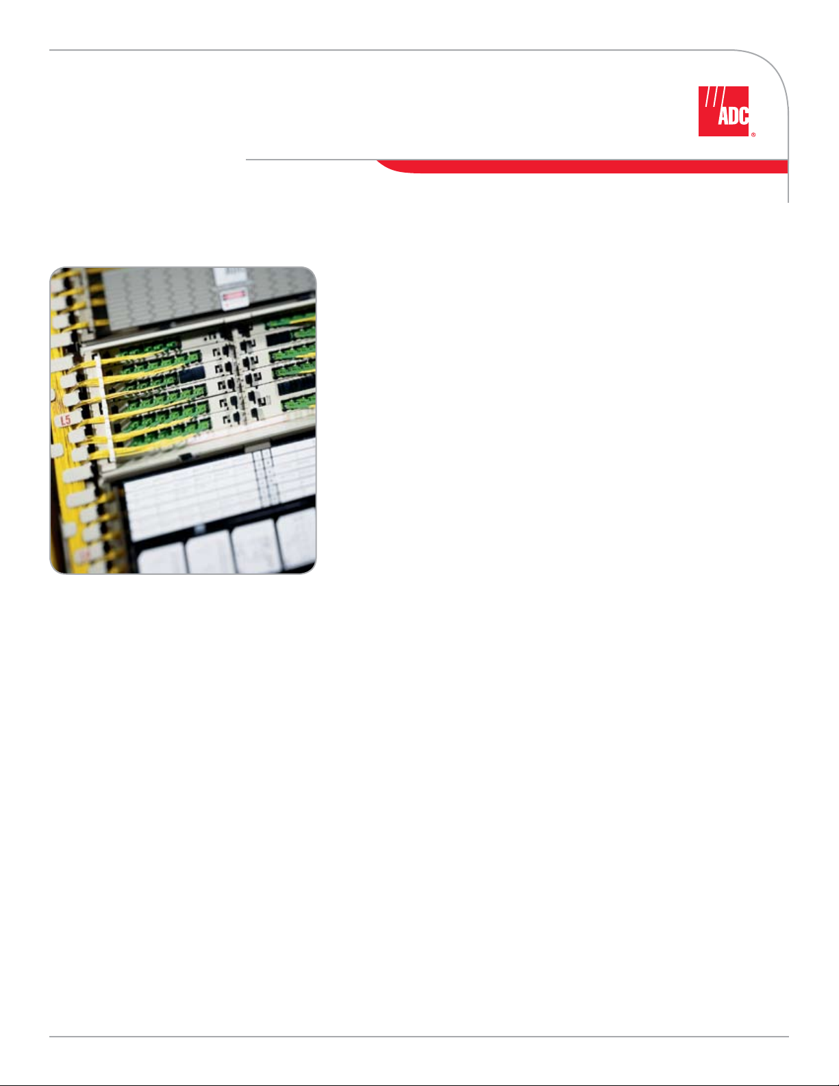
VAM (Value Added Modules) System
Monitor, Splitter, WDM & CWDM Modules & Chassis
One-stop-shop for complete optical transport system support requirements.
The VAM System consists of a variety of chassis and value-added modules
housing various optical components that fit into existing ADC fiber distribution
frames and along with various other mounting environments.
VAM Modules
Provide optical monitoring, splitting or multiplexing/demultiplexing of optical
signals. Monitoring enables providers to troubleshoot networks without forcing
disruption of services. Splitting allows for the distribution of signals to multiple
subscribers. WDM/CWDM technologies allow multiple wavelengths of light to
travel together in a single strand of fiber.
Modules are available in these configurations:
Monitor — save time trouble shooting non-intrusively; labeled and
•
configured for monitoring applications
Splitter — distribute signals to multiple subscribers; labeled and configured
•
for splitting applications
WDM — add more capacity to existing optical networks; allows multiple
•
wavelengths on a single fiber
CWDM — add even greater capacity with more granular splitting and
•
combining options
w w w . a d c . c o m • + 1 - 9 5 2 - 9 3 8 - 8 0 8 0 • 1 - 8 0 0 - 3 6 6 - 3 8 9 1
Page 2
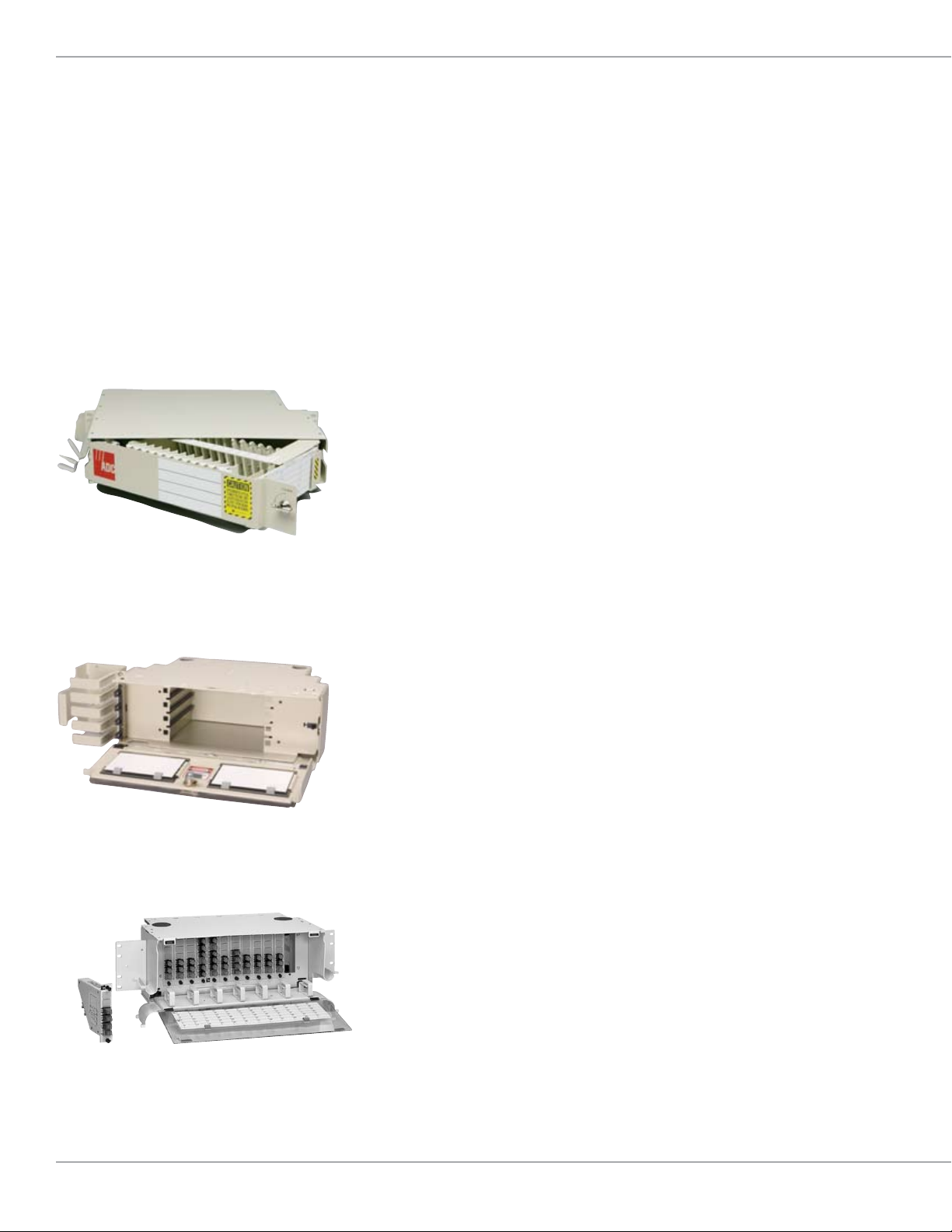
NG3 MicroVAM Chassis
VAM Chassis
Purpose is to house the modules containing the optical
components.
FMT MicroVAM Chassis
• Accommodates up to 12 microVAM modules
• Designed to mount in a 2 RU FMT
NG3 MicroVAM Chassis
• Accommodates up to 14 microVAM modules
• Designed to mount in NG3 frame
ODF (Industry Standard) or FCM (ADC only)
WideVAM™ Chassis
• Higher density version of the Standard VAM Chassis
• Accommodates up to 6 modules (wide)
• Wide variety of chassis options available including 19" and
23" rack mount with various depths
FCM Standard VAM Chassis (ADC only)
• Designed to fit in an ADC FDF rear load frame ONLY with
unique mounting
• Front and rear load versions available
• Accommodates 12 modules per chassis
FL2–VAM Chassis door open
LGX® Compatible VAM Chassis
w w w . a d c . c o m • + 1 - 9 5 2 - 9 3 8 - 8 0 8 0 • 1 - 8 0 0 - 3 6 6 - 3 8 9 1
ODF Standard VAM Chassis (Industry Standard)
• Mounts into virtually any 19"/23" style rack
• 2, 4, 6, 8, 12 modules per chassis options available
• 1.75"-7" H versions
FL2000 VAM Chassis
• All front access VAM module solution
• Chassis available with 4, 6 or 9 modules mounting positions
• Designed for FL2000 panel environments
LGX® Compatible VAM Chassis
®
• Fits to form factor of the industry standard LGX
panel
• 7" H chassis accommodates up to 12 modules
• Front and rear access
Page 3

Single VAM Plug-in
VAM Type Best Application
Front Load or Rear Load Style Fiber Distribution
8 inch High FCM Chassis
7 inch High ODF Chassis 7 inch Style FDF Frames and/or 19"/23" Racks 12 6 Front, 4 Rear
5.25 inch High ODF VAM Chassis 19"/23" Channel or Network/UEF Style Frames 8 6 Front, 4 Rear
4 inch High ODF VAM Chassis 19"/23" Channel or Network/UEF Style Frames 6 6 Front, 4 Rear
3.5 inch High ODF VAM Chassis 19"/23" Channel or Network/UEF Style Frames 4 6 Front, 4 Rear
1.75 inch High ODF VAM Chassis 19"/23" Channel or Network/UEF Style Frames 2 6 Front, 4 Rear
FL2000 VAM Chassis 19"/23" Rack or Cabinet Type Applications 4, 6 or 9 6 Front
8 inch High FCM WideVAM Chassis
7 inch High WideVAM Chassis 7 inch Style FDF Frames and 19"/23" Racks 6 WideVAMs 18 Front, 12 Rear
3.5 inch High WideVAM Chassis 19"/23" Channel or Network/UEF Style Frames 2 WideVAMs 18 Front, 12 Rear
7 inch High LGX VAM Chassis LGX Style Frame Environments 12 LGX VAMs 6 Front, 3 Rear
3.5 inch High LGX VAM Chassis LGX Style Frame Environments 4 LGX VAMs 6 Front, 3 Rear
3.5 inch High (2RU) MicroVAM Chassis 19"/23" Channel or Network/UEF Style Frames 12 MicroVAMs 6 Front
NG3 MicroVAM Chassis NG3 Style Frame System Only 14 MicroVAMs 6 Front
* Standard Form Factor Connector
Frames Only 12 6 Front, 4 Rear
Front Load or Rear Load Style Fiber Distribution
Frames Only 6 WideVAMs 18 Front, 12 Rear
Module Capacity
Available Ports
Per VAM Module*
w w w . a d c . c o m • + 1 - 9 5 2 - 9 3 8 - 8 0 8 0 • 1 - 8 0 0 - 3 6 6 - 3 8 9 1
Page 4

Central Office
FL1000 Wallbox
Fiber Raceway
Solutions
(FiberGuide®)
Traditional
FDF Lineup
Solutions
(8" FCM, LSX)
High-Density
FDF Lineup
Solutions
(NGF, NG3)
Cable Entrance
Solutions
(FEC)
Intermediate FDF Solutions
(8" FCM)
6"
6"
12"
24"
12"
FL2000
Panel
FiberGuide®
Flex Tubing
FiberGuide
Express Exit
RiserGuide
™
FPL
Panel
Vertical
FiberGuide
6"
6"
6"
6"
FMT
Panel
Fiber Optic
12"
Transport Lineup
Fiber Optic
Panel Solutions
(FOP)
Fiber Cable Assembly
Value-Added Module
(VAM) Solutions
& Connector Solutions
(FCC)
(Monitors, Splitters, WDM, CWDM)
Splice Vault
Customer Premises
Level 3
FL1000 Wall Box
Plenum FiberGuide
®
Level 2
FL2000 Wall Mount Panel
Plenum FiberGuide
Level 1
OMX 600® Fiber Distribution Frame
Plenum FiberGuide
VAMs
Web Site: www.adc.com
From North America, Call Toll Free: 1-800-366-3891 • Outside of North America: +1-952-938-8080
Fax: +1-952-917-3237 • For a listing of ADC’s global sales office locations, please refer to our Web site.
ADC Telecommunications, Inc., P.O. Box 1101, Minneapolis, Minnesota USA 55440-1101
Specifications published here are current as of the date of publication of this document. Because we are continuously
improving our products, ADC reserves the right to change specifications without prior notice. At any time, you may
verify product specifications by contacting our headquarters office in Minneapolis. ADC Telecommunications, Inc.
views its patent portfolio as an important corporate asset and vigorously enforces its patents. Products or features
contained herein may be covered by one or more U.S. or foreign patents. An Equal Opportunity Employer
104215AE 3/07 Original © 2007 ADC Telecommunications, Inc. All Rights Reserved
 Loading...