

Page 1

FlexWave™ Base Station System
IP-Based RAN for Indoor/Outdoor Coverage and Capacity
The FlexWave™ Base Station System (BSS) is a complete base station system providing converged
in-building and outdoor GSM, GPRS and EDGE coverage and capacity. It includes the FlexWave
nanoBTS™ and the FlexWave microBTS together with a common base station controller and
common operation management software needed to integrate with existing mobile networks.
Spec Sheet
Taking advantage of the more than 2 billion GSM handsets in use globally together with existing
IP-based broadband infrastructure for backhaul, the FlexWave BSS enables operators to provide
cost-effective tailored capacity and coverage for target customers and deliver excellent return on
investment.
Features:
• Smallest fully functional GSM/EDGE picocell
BTS in the industry
• Fully sealed, maintenance free microBTS for
outdoor applications
• IP-based backhaul reduces costs
• Available for 900, 1800 and 1900MHz
bands
• Compliant with GSM specifications
• Integrates with existing TDM-based or
softswitch MSC
• Alarm management integration
• Single Ethernet connection to BTS
Applications:
• Enterprise in-building premise coverage
• Enterprise indoor/outdoor campus coverage
• Stadiums, subways, tunnels
• Outdoor macro network hole fill (coverage)
• Outdoor macro network hot spot (capacity)
• Rural areas/isolated villages
w w w . a d c . c o m • + 1 - 9 5 2 - 9 3 8 - 8 0 8 0 • 1 - 8 0 0 - 3 6 6 - 3 8 9 1
Page 2
FlexWave™ Base Station System
MSC
SGSN
OMC-R
Client
OMC-R
Server
A Interface
n x E1/T1
Gb FR
n x E1/T1
IP
Network
IP
Network
FlexWave
nanoBTS
FlexWave
BSC
Abis over IP backhaul
Abis over IP per BTS
Ethernet
CORBA
OMC-R to BSC
Ethernet
Abis over IP
Ethernet
FlexWave
microBTS
4 TRX GSM/EDGE
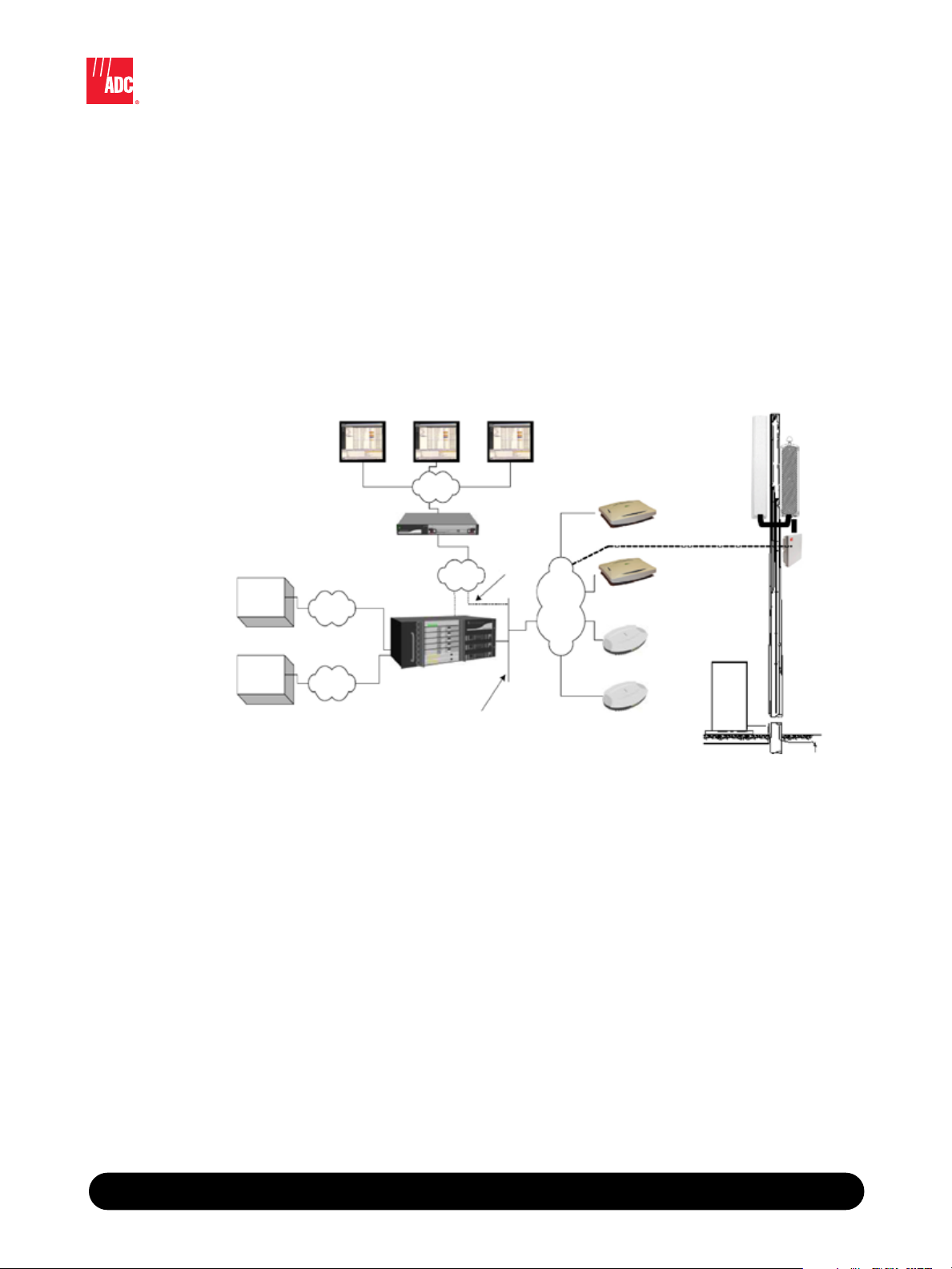
IP-Based RAN for Indoor/Outdoor Coverage and Capacity
System Architecture
The FlexWave nanoBTS and microBTS units present a standard Um air interface to the handset, while the
FlexWave Base Station Controller (BSC) interfaces with existing standard TDM-based MSC and SGSN
core network elements. Furthermore, with its PoE capability, the FlexWave microBTS can be combined
with WiMAX backhaul units for quick deployment in many areas. The indoor FlexWave nanoBTS units
and the outdoor FlexWave microBTS share a common BSC and Operations and Management Center–
Radio (OMC-R) and can also share a common IP backhaul network. This can result in significant CAPEX
and OPEX savings versus disparate solutions. This common approach also makes it easier for RF planning
engineers to target radio capacity exactly where needed in the network, without having to sacrifice
outdoor coverage and capacity at the expense of providing in-building coverage.
Operational management of the whole system is provided by the FlexWave OMC-R, which supports the
configuration of the system together with performance management and alarm monitoring.
Base Station System
™
FlexWave
4 / 0 7 • 1 0 4 6 2 5 A E
FlexWave BSS Network Diagram
Benefits:
• Increase ARPU via increased customer loyalty
• Create a foundation for fixed mobile convergence to support IMS services
• Reduce CAPEX and OPEX via a single IP backhaul network for all services
• Extend coverage and capacity in hard to reach areas
• Increase network capacity to support bandwidth intensive services (video)
• Provide faster time to service
• Allows simple handoff control between in-building and the wide area cellular coverage
• Provide single management and provisioning interface for indoor and outdoor applications
• Increase coverage and capacity where and when you need it; on demand
w w w . a d c . c o m • + 1 - 9 5 2 - 9 3 8 - 8 0 8 0 • 1 - 8 0 0 - 3 6 6 - 3 8 9 1
2
Page 3

FlexWave™ Base Station System
IP-Based RAN for Indoor/Outdoor Coverage and Capacity
FlexWave BSS Specifications
TELESERVICES Telephony
Short Message Service MT/PP
Short Message Service MO/PP
Short Message Service CB single message for user cell description
FORMATS
GSM speech format support:
AMR: full and half-rate, all codecs
Encryption: A5/1, A5/2
GPRS support:
E-GPRS support:
Circuit switched data:
FR, EFR
CS1-4
MCS1-9
Single slot BS20 at up to 14.4kb/s BS21-26, BS61, BS81
™
Base Station System
FlexWave
SUPPORTED FEATURES
Directed retry based on load, power and cell priority
Handover
Dynamic GPRS timeslot allocation (Dynamic PDCH)
Paging and location areas
BTS software download via BSC
Redundancy on SS7 links
Optional US regulation pack (E911)
Up to 4 nanoBTS can act as a Multi-TRX BTS
SECURITY
Air Interface:
Abis over IP interface
Signalling and management: TLS / AES
Voice - secure: RTP / AES
Channel assignment and classmark
A5/1, A5/2
FlexWave BSC Specifications
PERFORMANCE AND PHYSICAL
Processor capacity:
Input supply option:
Chassis: Compact PCI chassis with rear access to all traffic ports
Redundancy: Selective use of redundancy on vulnerable components (3PSUs, 7 fans,
INTERFACES Abis interface to the nanoBTS and microBTS
Standard A interface to MSC (4 or 8E1/T1)
Standard Gb to SGSN (4 E1/T1)
CORBA-based to O&M to OMC-R
15000 BHCA/BHLU
90-250 volts AC or 36-75 volts DC
RAID disks) and hot-plug capability for all modules
STANDARDS CE and FCC approved
4 / 0 7 • 1 0 4 6 2 5 A E
w w w . a d c . c o m • + 1 - 9 5 2 - 9 3 8 - 8 0 8 0 • 1 - 8 0 0 - 3 6 6 - 3 8 9 1
3
Page 4

FlexWave nanoBTS Specifications
FREQUENCIES Models for GSM900MHz (E-GSM), DCS1800 and PCS1900MHz bands
Each nanoBTS supports a single TRX and can act as a standalone BTS
STANDARDS CE marked - ETSI EN301 489-8
UL and FCC listed
ELECTRICAL INTERFACE
Power can be provided locally through a PSU kit or remotely using Power-over-Ethernet
MOUNTING Mounting bracket for wall or ceiling mounting
Single RJ45 auto-select 10/100 Ethernet supporting PoE
FlexWave microBTS Specifications
FREQUENCIES Models for DCS1800 and PCS1900MHz bands
Each microBTS supports up to 4 TRX
STANDARDS Pending
ELECTRICAL INTERFACE
Input power:
Network connection:
MOUNTING Pole wrap, pole mount, wall mount, ceiling mount, sub-terrain vault
90 – 265 VAC, 47 to 63 Hz, 300 Watts
Hardened RJ45 drop cable providing Power-over-Ethernet to IP backhaul device, per
IEEE 802.3af
FlexWave OMC-R Specifications
ALARMS Details of all alarms reported by FlexWave BTS units and FlexWave BSC
Interface for integration with 3rd party alarm management packages
CONFIGURATION Provisioning and re-configuring FlexWave BTS units and FlexWave BSC
Configures collection of GSM 12.04 and other BSC and BTS performance
measurements for off-line analysis
Spec Sheet
OPERATION Context sensitive help for selected managed object, MIB package, attribute and alarm
Back-up and restore
Circuit interface wizard (CIC) of the A interface to an MSC
CAPACITY
Users: Scalable according to server hardware
Infrastructure: Up to 2,500 TRX per server
The trademarks used are owned by ADC or their respective owners.
Web Site: www.adc.com
From North America, Call Toll Free: 1-800-366-3891 • Outside of North America: +1-952-938-8080
Fax: +1-952-917-3237 • For a listing of ADC’s global sales office locations, please refer to our Web site.
ADC Telecommunications, Inc., P.O. Box 1101, Minneapolis, Minnesota USA 55440-1101
Specifications published here are current as of the date of publication of this document. Because we are continuously
improving our products, ADC reserves the right to change specifications without prior notice. At any time, you may
verify product specifications by contacting our headquarters office in Minneapolis. ADC Telecommunications, Inc.
views its patent portfolio as an important corporate asset and vigorously enforces its patents. Products or features
contained herein may be covered by one or more U.S. or foreign patents. An Equal Opportunity Employer
104625AE 4/07 Original © 2007 ADC Telecommunications, Inc. All Rights Reserved
 Loading...