

Page 1
Avidia
SYSTEM CONFIGURATION AND MANAGEMENT
USER MANUAL
Catalog Number
SWD4573I1
SWITCHWARE VERSION 2.0
Page 2

December, 2000 Revision A
©Copyright 2000 ADC DSL Systems, Inc. All Rights Reserved.
ADC is a registered trademark of ADC Te l ecommunications, Inc. Avidia and Meg abit Modem are registered
trademarks and StarGazer, Swit ch W ar e and Avi dia Mu xW ar e ar e tra de marks of PairGain Techn ologies, Inc.
No right, license, or interest to such trademarks is granted hereunder, and you agree that no such right, license,
or interest shall be asserted by you with respect to such trademark.
Information contained in this document is company private to ADC DSL Systems, Inc., and shall not be
modified, used, copied, reproduced or disclosed in whole or in part without the written consent of ADC.
Other product names mentioned in this practice are used for identification purposes only and may be
trademarks or registered trademarks of their respective companies.
ii Avidia System Configu rati on and Management User Manual
Page 3

About This Manual
ABOUT THIS MANUAL
This manual documents the new configuration and management features included in
SwitchWare Version 2.0.
This manual is intended for system engineers responsible for configuring and managing an
Avidia System. It assumes a basic und erstan ding o f v oice an d data co mmun ications , inc luding
xDSL and ATM technologies. This manual is organized as follows:
Part I: Introduction and Setup
The chapters in this section provide an Av idia system configuration and managemen t overview,
and specific instructions for preparing to configure and manage a system. This section also
provides an overview of applications and features of the Avidia system. These overview
sections also indicate procedures you must complete using either the command-line in terface or
the Web interface to implement these features.
Part II: The Avidia command-line interface
These chapters provide instructions for configuring a system, monitoring performance, and
maintaining and administering a system using the Avidia system command-line interface.
Part III: The Avidia Web interface
These chapters provide instructions for configuring a system, monitoring performance, and
maintaining and administering a system using the Avidia system Web interface.
Appendix A provides guidance for troubleshooting and diagnostics.
Appendix B provides information about obtaining technical support, Avidia product warranty
and return procedures.
Appendix C provides a key to generated error message codes.
Appendix D provides a glossary of the terms used in this manual.
Avidia System Configuration and Management User Manual iii
Page 4
Document Conventions
DOCUMENT CONVENTIONS
Two types of messages, identified by icons, appear throughout the document:
Notes contain information about special circumstances.
Cautions indicate the possibility of equipment damage or the possibility of
personal injury.
COMMAND-LINE INTERFACE CONVENTIONS
The following typeface conventions are specific to the Command- Line Interface chapters of this
manual.
• Bold courier type indicates text to be typed exactly as shown.
• Unbolded courier type indicates onscreen messages or prompts.
• <Angle Brackets> indicate a parameter for which you need to pr ovide an appropriate
value.
• [Square Brackets] indicate an optional parameter.
• [<Angle brackets within square brackets>] indicate an optional
parameter that, should you include it, requires you to provide an appropriate value.
• (Multiple|Values) in parenthesis separated by a vertical line indicate that you must
select one of the values for that parameter. However, parentheses may also contain
parameters for which you need to provide a value. For example, (all|<port>)
indicates that you can type all to view all ports or type a port number to view a specific
port.
• Some optional parameters contain both a command and a parameter for which you need to
select from a finite set of values. For example, [-admin (up|down)] requires you to
type -admin up or -admin down, should you choose to include the parameter.
Optional parameters follow the required parameters in the command line, and can be
included in any order.
• Italic type indicates the format in which you type the information specified in the
procedure.
iv Avidia System Configu rati on and Management User Manual
Page 5

Web Interface Convent io ns
WEB INTERFACE CONVENTIONS
The following typeface conventions are specific to the Web-Based Interface chapters of this
manual.
• This font indicates a reference to an element on the screen.
• Italic type indicates the format in which you type the information specified in the
procedure.
SUMMARY OF CHANGES FOR VERSION 2.0
The following are features of the Avidia SwitchWare Version 2.0 software release:
• Avidia 2200 remote chassis with three slots including:
– a combination DS1 and management card
– ADSL user interface card
– POTS splitter card
• subtending for Avidia 2200 remote chassis
• SDSL cell-based user interface card
• IDSL frame-based user interface card including:
– Avidia system support for TLS, RAMP1483, and PPP services
– physical-layer loopback test
• Frame Relay for use with IDSL frame-based user interface card, including selection for
either FRF.5 or FRF.8 interworking
• card redundancy
• dual homing including redundant VCCs and VPC and static load-sharing
• rt-VBR and nrt-VBR traffic classes
• OAM F4 flow loopback
Avidia System Configuration and Management User Manual v
Page 6

Summary of Changes for Version 2.0
vi Avidia System Configuration and Management User Manual
Page 7

Table of Contents
TABLE OF CONTENTS
Part I: Introduction and Initial Setup ___________________________1
Chapter 1: Avidia System Configurat ion and Management Overview____________ ___3
Configuration Features........................................................................................................4
Performance Monitoring Features.......................................................................................6
System Administration and Diagnostic Features ................................................................7
Avidia System File Management ........................................... .................................. ...... .....8
Restoring System Files..........................................................................................8
How Image Files are Used....................................................................................8
How Configuration Files are Used........................................................................8
How Hardware Profile Files are Used ..................................................................9
Management Tools and Protocols.......................................................................................9
Chapter 2: Preparing for System Co nfiguration and Management ________________11
Step 1: Connect a Terminal and Log On...........................................................................12
Step 2: Set the Management Card IP Addresses...............................................................13
Setting the System IP Address, Subnet Mask and Default Gateway..................13
Setting the Gateway IP Address..........................................................................14
Displaying the System IP Addresses...................................................................14
Step 3: Select a Management Interface.............................................................................15
Step 4: Select an Access Method and Complete Setup.....................................................15
Accessing the Command-line Interface..............................................................15
Accessing the Web Interface...............................................................................16
Next Steps..........................................................................................................................17
Avidia System Configuration and Management User Manual vii
Page 8

Table of Cont en t s
Chapter 3: Applications and C onfiguration Overview ___________________________19
ATM...................................................................................................................................20
ATM Traffic Configuration.................................................................................20
ATM Traffic Management..................................................................................22
ATM Device Addresses ......................................................................................23
ATM Virtual Circuits..........................................................................................24
Frame Relay Transmission .......................... ..... .................................. ...... .........................26
SONET...............................................................................................................................28
Redundancy .......................................................................................................................28
Dual Homing.......................................................................................................29
Line Card Redundancy ........................................................................................32
Automatic Protection Switching .........................................................................33
Inband Management ..........................................................................................................35
Inband to Avidia..................................................................................................36
Inband to Modems...............................................................................................36
Inband for Subtending.........................................................................................37
Bridging and Routing.........................................................................................................37
Bridging and Spanning Tree Protocol.................................................................38
Routing................................................................................................................38
Encapsulation for Bridging, Routing, or Brouting..............................................39
Implementing Bridging/Routing/Brouting Sessions ...........................................41
Downloading Files to a Modem.........................................................................................44
Transparent LAN Service..... .................................. ...... ..... .................................. ...... ...... ..44
Subtending Multiple Systems............................................................................................45
Star Management.................................................................................................48
Daisy Chain Management...................................................................................52
viii Avidia System Configu r ati on and Management User Manual
Page 9

Table of Contents
OAM Alarms and Loopbacks............................................................................................57
About Alarm Surveillance...................................................................................57
About ATM Loopbacks ......................................................................................58
OAM Location ID...............................................................................................59
Preparing to Run OAM Loopbacks.....................................................................59
Example ATM-Layer Loopbacks ....................................................................... 61
After Running Loopbacks........................................ ...... ...... ...............................68
Avidia Alarm Manager....................................................................... ..... ...... ....................69
Configuring Avidia System Information............................................................. ..... .........69
Setting Up Connections.....................................................................................................70
DS1 Line/Management Combination Card.........................................................70
Frame-based Services..........................................................................................71
Cell-based Services.............................................................................................74
Saving Configurations.......................................................................................................75
Part II: The Avidia Command-Line Interface ____________________77
Chapter 4: Intr oduction to the Command-Line Int erface ________________________79
Logging On to the Command-Line Interface....................................................................80
Understanding Command-Line Interface Structure ..........................................................81
Navigating the Command-Line Interface..........................................................................82
Command-Line Interface Conventions.............................................................................82
Getting Help .................................... ..... ...... .................................. ...... ..... ..........................83
Logging Off the Command-Line Interface........................................................................83
Avidia System Configuration and Management User Manual ix
Page 10

Table of Cont en t s
Chapter 5: Configuring System Parameters ___________________________________85
Configuring System Information.......................................................................................86
Configuring the System Name............................................................................86
Configuring the System Contact.........................................................................87
Configuring the System Location........................................................................88
Configuring the System Date and Time..............................................................89
Configuring Boot File Information.....................................................................90
Displaying System Information...........................................................................91
Configuring IP Addresses..................................................................................................91
Configuring the System IP Address, Subnet Mask and Default Gateway..........92
Configuring the Gateway IP Address..................................................................93
Displaying the System IP Addresses...................................................................93
Configuring Trap Generation Status..................................................................................94
Configuring Trap Receivers...............................................................................................95
Adding Trap Receivers.............................................. .................................. ...... ..95
Displaying Trap Receivers..................................................................................96
Deleting Trap Receivers............................................ ...... ..... ...... .........................96
Configuring Community Strings .......................................................................................97
Adding Community Strings.............................................................. ..... ..............97
Displaying Community Strings...........................................................................98
Deleting Community Strings.......................... ..... .................................. ...... ...... ..98
Chapter 6: Configuring Subs criber Services ___________________________________99
Configuring ADSL Line Profiles.....................................................................................100
Adding ADSL Line Profiles..............................................................................100
Displaying ADSL Line Profiles........................................................................102
Deleting ADSL Line Profiles............................................................................103
x Avidia System Configuration and Management User Manual
Page 11

Table of Contents
Configuring ADSL Alarm Profiles .................................................................................104
Adding ADSL Alarm Profiles......................................................... ..................104
Displaying ADSL Alarm Profiles.....................................................................105
Deleting ADSL Alarm Profiles.........................................................................106
Configuring ADSL Handshaking....................................................................................107
Setting Handshaking Parameters.......................................................................107
Displaying Handshaking Parameters................................................................108
Configuring ADSL Service.............................................................................................109
Adding ADSL Port Configurations........................................... ...... ...... ............109
Displaying ADSL Port Configurations.............................................................110
Configuring SDSL Frame Line Profiles..........................................................................1 11
Adding SDSL Frame Line Profiles...................................................................112
Displaying SDSL Frame Line Profiles .............................................................1 12
Deleting SDSL Frame Line Profiles.................................................................113
Configuring SDSL Frame Alarm Profiles.......................................................................114
Adding SDSL Frame Alarm Profiles................................................................114
Displaying SDSL Frame Alarm Profiles...........................................................115
Deleting SDSL Frame Alarm Profiles ..............................................................116
Configuring SDSL Frame Service................................................................................... 1 17
Adding SDSL Frame Port Configurations........................................................117
Displaying SDSL Frame Port Configurations...................................................118
Configuring SDSL Cell Line Profiles .............................................................................119
Adding SDSL Cell Line Profiles....................................................................... 1 19
Displaying SDSL Cell Line Profiles.................................................................120
Deleting SDSL Cell Line Profiles.....................................................................121
Configuring SDSL Cell Alarm Profiles ..........................................................................121
Adding SDSL Cell Alarm Profiles....................................................................122
Displaying SDSL Cell Alarm Profiles..............................................................123
Deleting SDSL Cell Alarm Profiles..................................................................124
Avidia System Configuration and Management User Manual xi
Page 12

Table of Cont en t s
Configuring SDSL Cell Service ......................................................................................124
Adding SDSL Cell Port Configurations............................................................125
Displaying SDSL Cell Port Configurations ......................................................126
Configuring IDSL Line Profiles......................................................................................127
Adding IDSL Line Profiles ................................. ...... .................................. ......127
Displaying IDSL Line Profiles..........................................................................128
Deleting IDSL Line Profiles................................................. ...... .......................129
Configuring IDSL Alarm Profiles...................................................................................130
Adding IDSL Alarm Profiles .................................... ...... ..................................130
Displaying IDSL Alarm Profiles.......................................................................131
Deleting IDSL Alarm Profiles.................................................... ...... ..... ............133
Configuring IDSL Service...............................................................................................133
Modifying the IDSL Transmit Clock Source....................................................134
Displaying the IDSL Transmit Clock Source....................................................134
Modifying IDSL Port Configurations...............................................................135
Displaying IDSL Port Configurations...............................................................136
Configuring xDSL Subscriber Names.............................................................................138
Chapter 7: Configuring Network Services____________________________________141
Configuring OC3 Service................................................................................................142
Configuring the OC3 Interface Type.................................................................142
Displaying the Configured OC3 Interface Type...............................................143
Configuring DS1 Service.................................................................................................143
Configuring DS1 Ports......................................................................................144
Displaying DS1/T1 Port Configurations...........................................................146
Configuring DS3 Service.................................................................................................149
Configuring DS3 Ports......................................................................................149
Displaying DS3 Port Configurations.................................................................150
xii Avidia System Configu rati on and Management User Manual
Page 13

Table of Contents
Chapter 8: Configuring ATM Virtual Circuits________________________________1 53
Configuring ATM Traffic Profiles..................................................................................154
Adding ATM Traffic Profiles ...........................................................................155
Displaying ATM Traffic Profiles......................................................................156
Deleting ATM Traffic Profiles............................................. ..... ........................157
Configuring APS.............................................................................................................158
Configuring APS...............................................................................................158
Issuing Manual APS Commands ......................................................................159
Displaying APS Configuration .........................................................................160
Configuring PVPCs.........................................................................................................162
Viewing ATM Port Settings................................................. ..... ...... ...... ............162
Configuring Cell Channel Card PVPCs............................................................163
Changing Cell Channel Card PVPC Admin Status...........................................167
Deleting Primary and Backup Cell Channel Card PVPCs................................168
Displaying Cell Channel Card PVPC Information...........................................169
Configuring PVCCs.........................................................................................................170
Configuring Cell Channel Card PVCCs ...........................................................171
Configuring Frame Channel Card PVCCs........................................................179
Configuring SPVCs.........................................................................................................1 88
Adding SPVCs................................... ..... ...... .................................. ...... ..... .......189
Changing SPVC Admin Status .........................................................................190
Displaying SPVCs.............................................................................................191
Displaying SPVC Details..................................................................................193
Deleting SPVCs ............................................ ...... .................................. ..... .......194
Restarting SPVCs..............................................................................................195
Avidia System Configuration and Management User Manual xiii
Page 14

Table of Cont en t s
Configuring ATM Routing..............................................................................................196
Adding ATM Routing Table Entries......................... ...... ..... .............................196
Displaying ATM Routing Table Entries...........................................................197
Changing ATM Routing Admin Status.............................................................199
Deleting ATM Routing Table Entries......................................................... ......199
Configuring ATM Policing..............................................................................................200
ATM Port Policing............................................................................................200
PVC Policing.....................................................................................................201
PVP Policing ...................................... ...... .................................. ...... ..... ............202
Chapter 9: Configuring Frame Relay Interworking____________________________205
Configuring Frame Relay Links......................................................................................206
Adding a Frame Relay Link..............................................................................206
Modifying Frame Relay Link Settings..............................................................207
Deleting Frame Relay Links..............................................................................209
Displaying Frame Relay Link Settings .............................................................210
Configuring Frame Relay FRF.8 Circuits........................................................................211
Adding a Frame Relay FRF.8 Circuit ...............................................................212
Modifying Frame Relay FRF.8 Circuit Parameters..........................................215
Deleting Frame Relay FRF.8 Circuits ...............................................................217
Displaying Frame Relay FRF.8 Circuit Settings...............................................217
Configuring Frame Relay FRF.5 Circuits........................................................................219
Adding a Frame Relay FRF.5 Circuit ...............................................................220
Modifying Frame Relay FRF.5 Circuit Parameters..........................................222
Deleting Frame Relay FRF.5 Circuits ...............................................................224
Displaying Frame Relay FRF.5 Circuit Settings...............................................225
xiv Avidia System Configur atio n and Management User Manual
Page 15

Table of Contents
Chapter 10: Configuring Bridging and Routing _______________________________227
Configuring Bridging and Routing Sessions...................................................................228
Adding Sessions.............................................................................. ...... ............228
Modifying Sessions...........................................................................................230
Displaying Sessions ..........................................................................................233
Deleting Sessions ................................................ ..... .................................. ...... .235
Configuring IP Routing...................................................................................................235
Adding IP Routing Table Entries............................. ...... .................................. .236
Displaying the IP Routing Table.......................................................................2 36
Deleting IP Routing Table Entries....................................... ..... ........................239
Configuring IP ARP........................................................................................................239
Adding IP ARP Table Entries............................................................... ............240
Displaying the IP ARP Table............................................................................240
Deleting IP ARP Table Entries .........................................................................241
Modifying RIP Configuration .........................................................................................242
Modifying RIP ..................................................................................................242
Displaying the RIP Configuration Table...........................................................243
Configuring Destination-MAC Address Filtering (Forwarding) ....................................245
Adding Destination-MAC Address Filtering Table Entries..............................245
Displaying the Destination-MAC Address Filtering Table ..............................246
Deleting Destination-MAC Address Filtering Table Entries............................247
Configuring System Bridging Parameters.......................................................................247
Modifying System Bridging Parameters...........................................................248
Displaying System Bridging Parameters ..........................................................248
Configuring System STP Parameters..............................................................................2 49
Modifying System STP Parameters..................................................................249
Displaying System STP Parameters..................................................................250
Avidia System Configuration and Management User Manual xv
Page 16

Table of Cont en t s
Configuring Global IP Routing Settings..........................................................................251
Configuring Global IP Routing Settings...........................................................251
Displaying Global IP Routing Settings.............................................................251
Chapter 11: Configuring Subtended Systems _________________________________253
Adding a Subtended System............................................................................................254
Modifying a Subtended System Configuration ...............................................................255
Displaying Subtending Information.................................................................................257
Chapter 12: Monitoring Subscriber Connections ______________________________259
Monitoring ADSL Performance......................................................................................260
Monitoring ADSL Loop Status.........................................................................260
Monitoring ADSL Performance History...........................................................262
Monitoring SDSL Frame Performance............................................................................264
Displaying SDSL Frame Line Statistics............................................................264
Displaying SDSL Frame Performance History.................................................266
Monitoring SDSL Frame CPE Statistics .........................................................................267
Monitoring SDSL Cell Performance...............................................................................268
Displaying SDSL Cell Line Statistics...............................................................268
Displaying SDSL Cell Performance History.....................................................270
Displaying SDSL Cell TC Layer Statistics.......................................................271
Clearing SDSL Cell Statistics ...........................................................................273
Monitoring IDSL Current Performance...........................................................................274
Monitoring IDSL Current Performance............................................................274
Chapter 13: Monitoring Network Connections ________________________________277
Monitoring SONET Performance....................................................................................278
Monitoring SONET Medium Statistics.............................................................278
Monitoring SONET Section Statistics ..............................................................280
Monitoring SONET Line Statistics...................................................................281
Monitoring SONET Path Statistics ...................................................................283
xvi Avidia System Configur atio n and Management User Manual
Page 17

Table of Contents
Monitoring DS1/T1 Performance....................................................................................286
Monitoring DS3 Performance .........................................................................................289
Monitoring ATM Connection Statistics..........................................................................292
ATM PVCC Connection Statistics....................................................................292
ATM PVPC Connection Statistics....................................................................293
Monitoring APS Status....................................................................................................295
Monitoring Frame Relay Performance Statistics ............................................................296
Monitoring Link Statistics.................................................................................296
Monitoring LMI Statistics................................................................................. 2 98
Monitoring Circuit Statistics.............................................................................299
Monitoring FRF.5 Statistics..............................................................................302
Monitoring FRF.8 Statistics..............................................................................303
Chapter 14: Monitoring Bridging and Routing________________________________305
Monitoring Bridge Port Status.........................................................................................306
Monitoring STP Port Status.............................................................................................307
Monitoring System Bridge/STP Statistics.......................................................................309
Monitoring System IP Statistics......................................................................................311
Monitoring Bridge Forwarding Statistics........................................................................313
Chapter 15: Monitoring Physical Interfaces __________________________________315
Monitoring ADSL Interfaces...........................................................................................316
Monitoring SDSL Frame Interfaces................................................................................317
Monitoring SDSL Cell Interfaces....................................................................................319
Monitoring DS1 Interfaces..............................................................................................320
Monitoring DS3 Interfaces..............................................................................................322
Monitoring OC3 Interfaces..............................................................................................324
Monitoring Interfaces......................................................................................................325
Avidia System Configuration and Management User Manual xvii
Page 18

Table of Cont en t s
Chapter 16: Monitoring System Alarms and Status ____________________________327
Monitoring System Alarms and Events...........................................................................328
Monitoring SDSL Frame Alarms ....................................................................................331
Monitoring SDSL Frame Alarm Status.............................................................331
Monitoring SDSL Frame Alarm History...........................................................333
Monitoring SDSL Cell Alarms........................................................................................334
Monitoring IDSL Alarm Status.......................................................................................337
Monitoring System Hardware Status...............................................................................339
Chapter 17: System Maintenance and Administration__________________________341
Configuring and Initiating OAM Loopbacks...................................................................342
Setting the System OAM Source Location ID..................................................342
Configuring and Initiating OAM Loopbacks....................................................343
Initiating Communication Path Loopbacks.....................................................................345
Initiating OC3 Loopbacks.................................................................................346
Initiating DS1 Loopbacks..................................................................................346
Initiating DS3 Loopbacks..................................................................................347
Managing IDSL Diagnostics ........................................ ..... ...... .................................. ......348
Clearing Statistics............................... .................................. ...... ...... .................348
Configuring and Initiating IDSL Loopbacks.....................................................349
Configuring and Initiating Corrupted CRCs.....................................................350
Displaying IDSL Loopback and Corrupted CRC Test Configurations.............351
Detecting Network Devices..................................................... ...... ..................................353
Managing Image Files ...................................... ...... ...... .................................. ..... ............354
Uploading Files to a TFTP Server.....................................................................354
Downloading Files from a TFTP Server...........................................................355
Copying Files ....................................................................................................356
Displaying a Directory of Files on a Card.........................................................357
Downloading Files to a Modem.......................................................................................358
xviii Avidia System Configur atio n and Management User Manual
Page 19

Table of Contents
Managing Security............................................ ..... ...... .................................. ...... ..... .......359
Adding User Accounts......................................................................................359
Displaying User Accounts.................................................................................361
Modifying User Accounts.................................................................................361
Deleting User Accounts ................................ ...... ..... .................................. ...... .363
Changing a User Password....................................... ...... .................................. .364
Displaying System Inventory..........................................................................................364
Viewing SDSL Frame CPE general information ............................................................365
Rebooting Cards..............................................................................................................366
Rebooting the System .......................................................................................366
Rebooting an Individual Card...........................................................................367
Setting the Command-Line Interface Timeout Option....................................................367
Deleting Files.............................................. ...... ..... .................................. ...... ...... ............368
Part III: The Avidia Web Interface ___________________________369
Chapter 18: Introduction to the Web Interface________________________________371
Logging On to the Web Interface....................................................................................372
Navigating the Web Interface..........................................................................................374
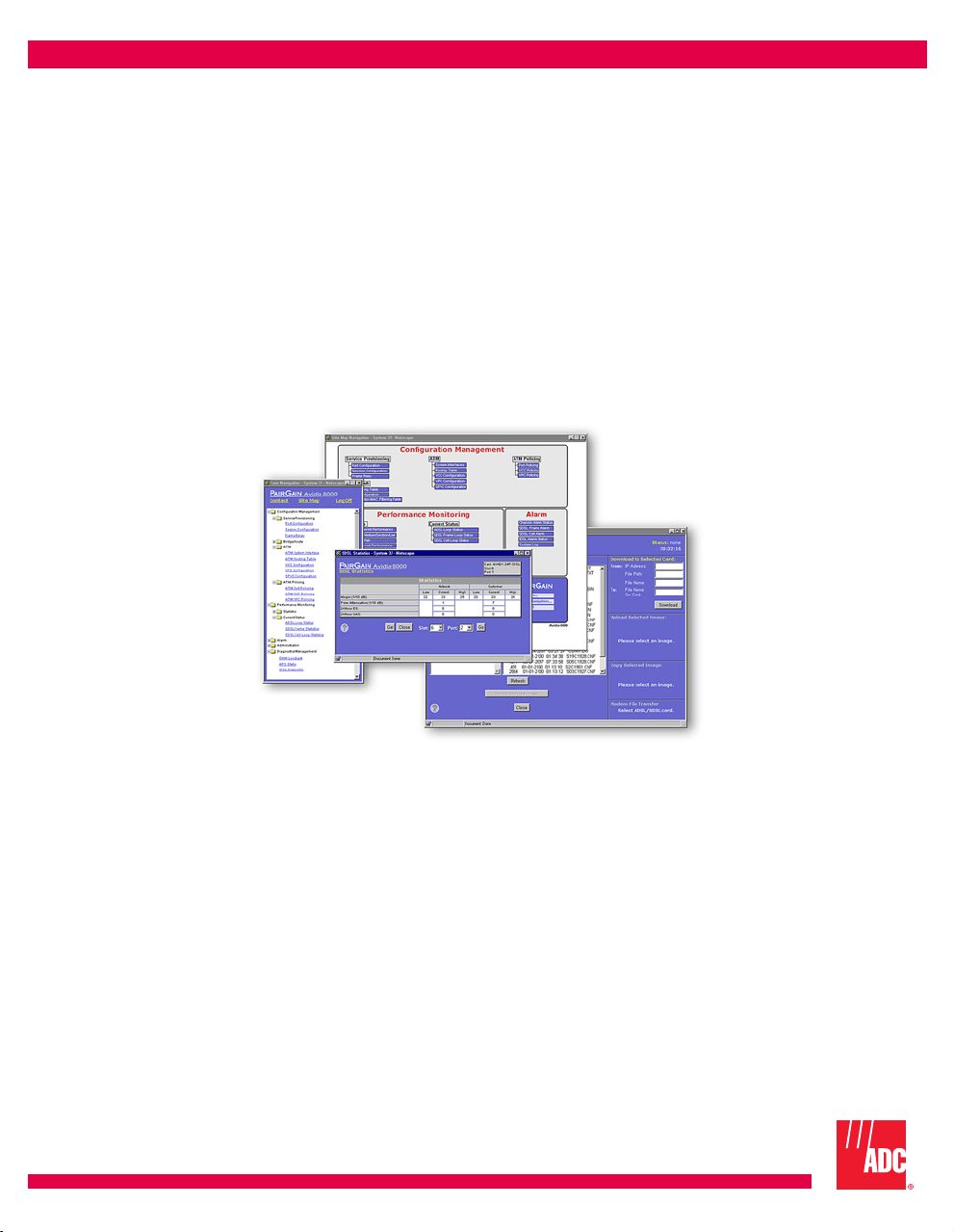
Site Map Navigation Window...........................................................................374
Tree Navigation Window..................................................................................375
Web Interface Conventions.............................................................................................376
Getting Help .................................... ..... ...... .................................. ...... ..... ........................376
Logging Off the Web Interface.......................................................................................376
Chapter 19: Configuring System Parameters _________________________________377
Configuring System Identification..................................................................................380
Configuring Management Card IP Addresses.................................................................381
Configuring System Trap Generation Status...................................................................382
Configuring Boot File Information .................................................................................3 82
Configuring System Date and Time................................................................................384
Avidia System Configuration and Management User Manual xix
Page 20

Table of Cont en t s
Chapter 20: Configuring Subscriber Services _________________________________385
Configuring ADSL Line Profiles.....................................................................................386
Configuring ADSL Alarm Profiles..................................................................................388
Configuring ADSL Service .............................................................................................391
Configuring SDSL Frame Line Profiles..........................................................................393
Adding SDSL Frame Line Profiles...................................................................394
Deleting SDSL Frame Line Profiles .................................................................394
Configuring SDSL Frame Alarm Profiles.......................................................................395
Adding SDSL Frame Alarm Profiles................................................................395
Deleting SDSL Frame Alarm Profiles...............................................................396
Configuring SDSL Frame Service...................................................................................397
Configuring SDSL Cell Line Profiles..............................................................................399
Adding SDSL Cell Line Profiles.......................................................................400
Deleting SDSL Cell Line Profiles.....................................................................401
Configuring SDSL Cell Alarm Profiles...........................................................................401
Adding SDSL Cell Alarm Profiles....................................................................402
Deleting SDSL Cell Alarm Profiles..................................................................403
Configuring SDSL Cell Service ......................................................................................404
Configuring IDSL Line Profiles......................................................................................406
Adding IDSL Line Profiles ................................. ...... .................................. ......407
Deleting IDSL Line Profiles................................................. ...... .......................408
Configuring IDSL Alarm Profiles...................................................................................408
Adding IDSL Alarm Profiles .................................... ...... ..................................409
Deleting IDSL Alarm Profiles.................................................... ...... ..... ............410
Configuring IDSL Service...............................................................................................411
Chapter 21: Co nfiguring Network Services _________________ __________________415
Configuring OC3 Service................................................................................................416
Configuring DS1 Service.................................................................................................417
Configuring DS3 Service.................................................................................................422
xx Avidia System Configuration and Ma nagement User Manual
Page 21

Table of Contents
Chapter 22: Configuring ATM Virtual Circuits _______________________________427
Configuring ATM Traffic Profiles..................................................................................428
Adding ATM Traffic Profiles ...........................................................................429
Deleting ATM Traffic Profiles............................................. ..... ........................430
Configuring APS.............................................................................................................430
Configuring APS...............................................................................................431
Issuing Manual APS Commands ......................................................................432
Configuring PVPCs.........................................................................................................433
Adding Primary PVPCs ............................................................ ...... ..................434
Changing PVPC Admin Status .........................................................................437
Deleting PVPCs ............................................ ...... ..... .................................. ...... .438
Adding Backup PVPCs.................................................. ...... ..... ........................439
Deleting Backup PVPCs ...................................................... ..... ........................441
Returning Service from a Backup PVPC to a Primary PVPC..........................442
Configuring PVCCs.........................................................................................................443
Adding Primary PVCCs...................................... ..... .................................. ...... .444
Changing PVCC Admin Status.........................................................................448
Deleting PVCCs....................................................... ...... ...... .............................449
Adding Backup PVCCs................................. ...... .................................. ..... .......450
Deleting Backup PVCCs............................... .................................. ...... ..... .......452
Returning Service from a Backup PVCC to a Primary PVCC .........................453
Configuring SPVCs.........................................................................................................4 54
Configuring ATM Routing..............................................................................................457
Configuring ATM Interface Information........................................................................460
Configuring ATM Policing .............................................................................................462
ATM Port Policing............................................................................................462
PVCC Policing..................................................................................................464
PVPC Policing ..................................................................................................465
Avidia System Configuration and Management User Manual xxi
Page 22

Table of Cont en t s
Chapter 23: Co nfiguring Frame Relay Interworking _ _____________ _____________467
The Frame Relay Interworking Configuration Table......................................................468
Adding a Frame Relay Configuration..............................................................................470
Modifying a Frame Relay Configuration.........................................................................475
Viewing an Entire Frame Relay Configuration...............................................................478
Deleting a Frame Relay Configuration............................................................................483
Chapter 24: Configuring Bridging and Routing _______________________________485
Configuring Bridging and Routing Sessions...................................................................486
Adding Sessions............................................. .................................. ..... ............488
Modifying Sessions...........................................................................................491
Deleting Sessions ............................................................................. ..... ............493
Configuring Router Groups.............................................................................................493
Adding Router Groups .............................................. ...... ..................................494
Deleting Router Groups.................................................................... ..... ............494
Configuring IP Routing ...................................................................................................495
Adding IP Routing Table Entries.......................................................... ............496
Deleting IP Routing Table Entries ....................................................................497
Modifying RIP Configuration..........................................................................................497
Configuring System Bridging and STP Parameters ........................................................500
Modifying System Bridging Parameters...........................................................501
Modifying System STP Parameters ..................................................................502
Configuring Global IP Routing Settings..........................................................................502
Chapter 25: Monitoring Subscriber Connections ______________________________505
Monitoring ADSL Status.................................................................................................506
Monitoring SDSL Frame Current Statistics.....................................................................510
Monitoring SDSL Cell Performance...............................................................................512
Monitoring IDSL Performance ........................................................................................515
xxii Avidia System Configuration and Manageme nt User Manual
Page 23

Table of Contents
Chapter 26: Monitoring Network Connections________________________________517
Monitoring SONET Performance....................................................................................5 18
Medium/Section/Line Current Performance.....................................................518
Path Current Performance.................................................................................522
Monitoring DS1 Performance .........................................................................................524
Monitoring E1 Performance............................................................................................527
Monitoring DS3 Performance .........................................................................................530
Monitoring APS Status....................................................................................................532
Chapter 27: Monitoring Physical Interfaces __________________________________535
Opening the Interface Window........................................................................................536
Physical SONET Interfaces.............................................................................................538
Physical ADSL Interfaces ...............................................................................................538
Physical SDSL Frame Interfaces.....................................................................................5 39
Physical SDSL Cell Interfaces ........................................................................................5 40
Physical DS1 Interfaces...................................................................................................541
Physical E1 Interfaces .....................................................................................................541
Physical DS3 Interfaces...................................................................................................542
Chapter 28: Monitoring System Alarms and Status____________________________543
Monitoring System Events..............................................................................................5 44
Monitoring System Alarms .............................................................................................546
Monitoring SDSL Frame Alarms....................................................................................549
Monitoring SDSL Cell Alarms........................................................................................551
Monitoring IDSL Alarm Status.......................................................................................553
Chapter 29: System Maintenance and Administration__________________________ 557
Configuring and Initiating OAM Loopbacks..................................................................558
Initiating Communication Path Loopbacks.....................................................................563
OC3 Loopbacks.................................................................................................565
DS1 Loopbacks.................................................................................................566
DS3 Loopbacks.................................................................................................567
Avidia System Configuration and Management User Manual xxiii
Page 24

Table of Cont en t s
Managing IDSL Diagnostics ........................................ ..... ...... .................................. ......568
Detecting Network Devices..................................................... ...... ..................................570
Managing Image Files ...................................... ...... ...... .................................. ..... ............571
Uploading Files to a TFTP Server.....................................................................572
Downloading Files to the Avidia System..........................................................573
Copying Files ....................................................................................................576
Deleting Files ................................................................................... ..... ...... ......577
Downloading Files to a Modem.......................................................................................577
Managing Security....................................... .................................. ..... .............................580
Adding User Accounts ......................................................................................582
Deleting User Accounts............................................. ...... ..................................584
Modifying User Accounts.................................................................................584
Restoring the Admin Account Password...........................................................586
Configuring the System Timers.......................................................................................586
Setting the Inactivity Timeout...........................................................................587
Setting the Refresh Rate....................................................................................588
Displaying System Inventory...........................................................................................588
Resetting Cards................................................................................................................589
Activating and Deactivating Ports...................................................................................590
Part IV: Appendixes ______________________________________ 593
Appendix A: Troubleshooting and Diagnostics ________________________________595
Accessing the Boot Monitor............................................................................................595
Downloading an Image File from a TFTP Server...........................................................596
Booting the System..........................................................................................................598
Performing System Diagnostics.......................................................................................599
Detecting PCI Devices ................................... .................................. ..... ...... ......599
Performing NAND EEPROM Diagnostics.......................................................599
Testing the TRAM CUBIT................................................................................600
Setting the System Date and Time...................................................................................601
xxiv Avidia System Configu r ati on and Management User Manual
Page 25

Table of Contents
Appendix B: Contacting ADC ______________________________________________603
Technical Support............................................................................................................603
World Wide Web......................................................... ...... .................................. ..... ...... .603
Limited Warranty ................................................................... ...... ...... .............................603
Advance Replacement.....................................................................................................604
Billing..............................................................................................................................605
Returns.............................................................................................................................605
Appendix C: SPVC Last Release CauseCodes_________________________________607
Appendix D: Glossary _____________________________________________________611
Index_______________________________________________________________________617
Avidia System Configuration and Management User Manual xxv
Page 26

Table of Cont en t s
xxvi Avidia System Configu r atio n and Management User Manual
Page 27

PART I
INTRODUCTION AND INITIAL SETUP
This section contains the following chapters, which provide an overview of Avidia system
configuration and management and specific instructions for p reparing to configure and manage
a system.
Chapter Number Chapter Title Page
1 Avidia System Configuration and Management Overview 3
2 Preparing for System Configuration and Management 11
3 Applications and Configuration Overview 19
Avidia System Configuration and Management User Manual 1
Page 28

2 Avidia Syst em Configuration and Manageme nt User Manual
Page 29

AVIDIA SYSTEM CONFIGURATION
AND
Each Avidia® system provides two different user interfaces for system configuration and
management. Both interfaces are preinstalled on the management card.
The command-line interface provides comprehensive system configuration and management
features using a text-only interface. You access the command-line interface using either an
ASCII terminal or a PC running a terminal emulation program, connected to the management
card craft port. Once the management card IP address is configured, you can also access the
command-line interface remotely using a telnet application. The command-line interface
contains a hierarchy of different prompts, at which you type commands to perform a particular
configuration or management task.
The Web interface is a graphical user interface (GUI) that provides the most of the system
configuration and management features in the command-line interface, as well as additional
security features. You access the Web interface using a PC co nnected to the Fast Ether net po rt
on the back of the Avidia chassis, or over a network. The Web interface provides two different
styles of navigati on — the Site Map Navigat ion window and the Tree Navigation window. F rom
either navigation window, you select the configuration or management task you want to
perform.
MANAGEMENT OVERVIEW
1
Avidia System Configuration and Management User Manual 3
Page 30

Configuration Features
CONFIGURATION FEATURES
The Avidia system enables you to configure:
• system information, such as system name and location, contact, date and time
• management card IP address, subnet mask, and default gateway
• trap receivers and trap generation status
• community strings
• ATM traffic profiles that define the traffic type and Quality of Service (QoS) on a specific
channel. ATM traffic profiles are applied to permanent Virtual Channel Connections
(VCCs) and Virtual Path Connections (V PCs) during configuration.
• ATM VCC, VPC, and port policing
• bridging and routing sessions
• Frame Relay traffic profiles that define the traffic type and Quality of Service (QoS) on a
specific channel. Frame Relay traffic profiles are applied to Permanent Virtual Channels
(PVCs) during configuration. You can also specify either FRF.5 or FRF.8 interworking.
• ADSL cell-based card line profiles that define the rate mode, target margin, minimum and
maximum interleave transmit rate, and interleave depth. ADSL line profiles are applied to
ADSL channels during configuration.
• ADSL cell-based card alarm profiles that define the Loss Of Frame (LOF), Loss Of Signal
(LOS) and Errored Seconds (ES) thresholds. ADSL alarm profiles are applied to ADSL
channels during configuration.
• SDSL cell-based card line profiles that define the rate mode, target margin, minimum and
maximum interleave transmit rate, and interleave depth. SDSL cell line profiles are applied
to cell-based SDSL channels during configuration.
• SDSL cell-based card alarm profiles that define the Loss Of Frame (LOF), Loss Of Signal
(LOS) and Errored Seconds (ES) thresholds. ADSL alarm profiles are applied to ADSL
channels during configuration.
4 Avidia Syst em Configuration and Manageme nt User Manual
Page 31

Chapter 1: Avidia System Config uration and Management Ove r vi ew
• SDSL frame-based card line profiles that define the transmission rate. SDSL line profiles
are applied to SDSL channels during configuration.
• SDSL frame-based card alarm profiles that enable or disable margin, ES, Unavailable
Seconds (UAS) and Loss of Sync Word (LOSW) alarms and define the alarm thresholds.
SDSL alarm profiles are applied to SDSL channels during configuration.
• IDSL frame-based card line profiles that define the transmission rate. SDSL line profiles
are applied to SDSL channels during configuration.
• IDSL frame-based card alarm profiles that enable or disable margin, ES, Unavailable
Seconds (UAS) and Loss of Sync Word (LOSW) alarms and define the alarm thresholds.
IDSL alarm profiles are applied to IDSL channels during configuration.
• ADSL cell-based service, including assigning ADSL line and ADSL alarm profiles
• SDSL cell-based service, including assigning cell-based SDSL line and SDSL alarm
profiles
• SDSL frame-based service, including assigning frame-based SDSL line and SDSL alarm
profiles
• IDSL frame-based service, including assigning IDSL line and IDSL alarm profiles
• xDSL subscriber names to identify the subscriber to which each port is connected
• ATM service, including setting up cell channel card VCCs and VPCs, and frame channel
card (SDSL frame-based and IDSL) VCCs
• Frame Relay service, including setting up PVCs for IDSL card
• OC3 service (SONET or SDH), with Automatic Protection Switching (APS)
• DS1/T1 service, including specifying line type, line code, circuit identifier, line length,
clocking type, and enabling or disabling DS1/T1 traps
• DS3 service, including specifying line type, line length, clocking type, and enabling or
disabling DS3 traps
Avidia System Configuration and Management User Manual 5
Page 32

Performance Monitoring Features
PERFORMANCE MONITORING FEATURES
The Avidia system enables you to display or monitor system status. The following status can be
seen through the Avidia command-line interface:
• ATM PVC and PVP connection statistics
• APS status
• bridge and STP port status
• system bridge/STP statistics, including bridge forwarding statistics
• system IP statistics
• ADSL loop status and performance history
• SDSL cell statistics and performance history
• SDSL frame statistics and performance history
• IDSL statistics and performance history
• SDSL CPE statistics
• SONET status and performance history, by Medium, Section, Line and Path
• DS1/T1 status and performance history
• DS3 status and performance history
• system physical interface statistics, all at once or by slot
• ATM cell switch interfaces
• system log
• system alarms and event status
• SDSL alarm history
• IDSL alarm status
6 Avidia Syst em Configuration and Manageme nt User Manual
Page 33

Chapter 1: Avidia System Config uration and Management Ove r vi ew
The following status can be seen through the Avidia Web interface:
• statistics
– IDSL current performance
– SONET medium/section/line
– SONET path
– DS1 current performance
– DS3 current performance
– physical slot interfaces
• current status
– ADSL loop status
– SDSL frame loop status
– SDSL cell loop status
SYSTEM ADMINISTRATION AND DIAGNOSTIC
EATURES
F
The Avidia system enables you to perform the following administrative functions :
• copying, deleting and displaying a directory of files using a DOS-like file system
• uploading files to and downloading files from a TFTP server
• downloading files to modems
• displaying system inventory, including ha rdware serial numbers and softw are version
numbers
• viewing CP E general inf ormation
• rebooting individual cards
• setting the system time-out value and Web-Based Interface performance data refresh rate
• activating and deactivating ports
• configuring and initiating OAM F4 and F5 flow loopbacks
• APS configuration and status
• IDSL diagnostics
Avidia System Configuration and Management User Manual 7
Page 34

Avidia System File Management
AVIDIA SYSTEM FILE MANAGEMENT
Each Avidia line, channel, and management card ships with the necessary system files
preinstalled in NVRAM (Non-Volatile Random Access Memory).
Restoring System Files
To restore system files for a card, copy a complete set of system files from the Avidia
MuxWare™ CD-ROM to that card. See “Managing Image Files” on page 354 fo r
command-line interface instructions or “Managing Image Files” on page 571 for Web interface
instructions.
How Image Files are Used
Each card in the Avidia system contains its own image files, which are stored in NVRAM and
have a .bin file name extension. Image files contain the firmware and software required to use
the hardware on which they reside. When you boot the Avidia system, each card runs a
bootstrap program that retrieves the image file out of NVRAM, decompresses it, then loads it
into Random Access Memory (RAM). The firmware runs from RAM during syst em operation.
How Configuration Files are Used
All configuration information for the Avidia system is stored permanentl y in the man a gement
card NVRAM. There is a separate ASCII configuration file for each card. The files are named
SnnCxxxx.cnf, where nn is the slot number and xxxx is the part number for that card.
During system startup, each line card and channel card retrieves its configuration file from the
management card and stores the information in RAM. If the management card is not installed,
or is not functioning, the line cards and channel cards can not boot.
If you remove a line or channel card and replace it with a new card of the same type, the new
card automatically loads the previous card’s configuration file from the management card into
RAM. To configure the new card differently, use one of the management interfaces to delete the
existing configuration then configure the card as desired. If you remove a line or channel card
and replace it with a new card of a different type, the card will not load the previous
configuration file.
8 Avidia Syst em Configuration and Manageme nt User Manual
Page 35
Chapter 1: Avidia System Config uration and Management Ove r vi ew
If you replace a management card, you can save the configuration files stored in the line and
channel card RAM to the management card NVRAM. However, the management card
configuration file containing all of the system profile information will be lost. Therefore, before
replacing a management card, back u p all of the co nfiguration files fr om NVRAM, then r estore
the files onto the new management card.
As soon as you make configurat ion changes, the info rmation is saved to R AM
on the management card and each of the cards affected by the configuration.
The changes are lost if you unplug or reboot the management card or any of
the cards affected by the configuration before you save the configuration
changes to NVRAM. You must proactively save the configuration chan ge to the
management card NVRAM using the Save command in either the Web interface
or the command-line interface.
How Hardware Profile Files are Used
A hardware profile text file (for example, amcprof.txt) is stored on each line, channel and
management card. This file contains the hardware serial numbers and version numbers for the
card. You can view this informa tion using the command-line interface (see “Displaying System
Inventory” on page 364) or the Web interface (see “Displaying System Inven t ory” on
page 588). You cannot edit this information.
MANAGEMENT TOOLS AND PROTOCOLS
Avidia systems use the following management tools and protocols, which enable you to perform
management tasks such as system configuration and performance monitoring:
• SNMP (Simple Network Management Protocol)
• TFTP (Trivial File Transfer Protocol)
• FTP (File Transfer Protocol)
• Telnet (for command-line interface access)
• HTTP (HyperText Transfer Protocol - for Web interface access)
• MIBs (Management Information Bases)
• Traps
Avidia System Configuration and Management User Manual 9
Page 36

Management Tools and Pro tocols
10 Avidia System Configu rati on and Management User Manual
Page 37

PREPARING FOR SYSTEM
CONFIGURATION AND
MANAGEMENT
Follow these steps to prepare for initial Avidia system configuration. To co nfig ure an Avid ia
system that is already in service, begin with Step 3.
1 Connect a terminal or PC running terminal emulation software to the management card
craft port. See “Step 1: Connect a Terminal and Log On” on page 12.
2 Use the Avidia command-line interface to set the management card IP address. See “Step
2: Set the Management Card IP Addresses” on page 13.
3 Determine whether you want to use the command-line interface or the Web interface to
configure and manage the system. See “Step 3: Select a Management Interface” on page 15.
4 Determine which method you want to use to access the selected management interface. See
“Step 4: Select an Access Method and Complete Setup” on page 15.
2
Avidia System Configuration and Management User Manual 11
Page 38

Step 1: Connect a Terminal and Log On
STEP 1: CONNECT A TERMINAL AND LOG ON
The first step in an initial Avidia system configuration is to set up a local connection to
the command-line interface. You access the command-line interface locally by connecting
either an ASCII terminal or a PC running a terminal emulation program to the management
card craft port.
1 Connect one end of an RS-232 DB9 cable to the serial port on an ASCII terminal or PC,
then connect the other end of the cable to the craft port on the front of the Avidia
management card.
Refer to your system Hardware Installation Manual for help locating the management card
craft port and for cabling pinouts.
2 Power up the ASCII terminal or PC.
3 If you are using a PC as a terminal, run a terminal emulation program such as
HyperTerminal or ProComm.
See the terminal emulation program documentation for instructions.
4 Configure your terminal or PC terminal emulation program as follows:
• baud rate: 9600 bps
• data bits: 8
• parity: none
• stop bits: 1
• flow control: none
5 If you are using a PC, in the terminal emulation program select the COM setting of the port
to which the RS-232 cable is connected (for example, COM1 or COM2).
6 Press to initiate the term inal s e ssion and display the username: prompt.
7 Type your user name, then press .
ENTER
ENTER
The user name admin is preconfigured for your use.
The Password prompt displ ays.
8 Type your password, then press .
ENTER
The password for the preconfigured admin user name is dslam.
The system displays a list of general commands and navigational tips, followed by the
::root=> prompt.
12 Avidia System Configu rati on and Management User Manual
Page 39

Chapter 2: Preparing for System Configuration and Management
STEP 2: SET THE MANAGEMENT CARD IP
DDRESSES
A
You set the management card IP address, subnet mask and default gateway (if one exists) to
enable communication with external networks and to enable access to the Web interface.
You cannot use IP addresses 192.168.1.0 through 192.168.21.255 with subnet
mask 255.255.255.0 as these addresses are restricted for internal Avidia
system use. In addition, you cannot currently manage the Avidia system in a
supernetting environment in which the IP addressing scheme contains Class
C IP addresses with a Class B subnet mask.
You configure IP addresses from the ::ip=> prompt. From the ::root=> prompt, type the
configuration ip command then press to display the ::ip=> prompt.
configuration ip
Setting the System IP Address, Subnet Mask and Default Gateway
ENTER
From the ::ip=> prompt, type the addr command in the following format then press .
addr <ipaddr> [<netmask>] [<defaultroute>]
Parameters
<ipaddr>
The management card IP address for the Avidia system. This address is based on the
Ethernet network to which the Avidia system is attached (format xxx.xxx.xxx.xxx). The
default management card IP address is 192.168.0.1.
[<netmask>]
The subnet mask associated with the management card IP address, if a subnet exists. This
address is based on the Ethernet network to which the Avidia system is attached (format
xxx.xxx.xxx.xxx).
[<defaultroute>]
The IP address of a router on the Ethernet network through which the Avidia system can
communicate with external networks (format xxx.xxx.xxx.xxx).
Avidia System Configuration and Management User Manual 13
ENTER
Page 40

Step 2: Set the Management Card IP Addresses
Examples
::ip=> addr 192.168.0.1 255.255.255.0
::ip=> addr 192.168.0.1
::ip=> addr 192.168.0.1 255.255.255.0 192.168.0.100
Setting the Gateway IP Address
If a gateway exists on the network to which the Avidia system is attached and you did not
configure the gateway with the IP address, type the defaultroute command in the following
format then press .
defaultroute <gwaddr>
Parameter
<gwaddr>
The IP address of a router on the Ethernet network through which the Avidia system can
communicate with external networks (format xxx.xxx.xxx.xxx). The default gateway IP
address is 192.168.0.100.
ENTER
Example
::ip=> defaultroute 192.168.0.100
Displaying the System IP Addresses
To verify your configuration, from the ::ip=> prompt, type show then press . A
screen similar to the following displays.
::ip=> show
AMC Card Ethernet Port IP Address: 192.168.0.1
AMC Card Ethernet Port IP Subnet Mask: 255.255.255.0
AMC Card Default Gateway: 192.168.0.100
14 Avidia System Configu rati on and Management User Manual
ENTER
Page 41

Chapter 2: Preparing for System Configuration and Management
STEP 3: SELECT A MANAGEMENT INTERFACE
You can perform most of the same system configuratio n and management functions using either
the command-line interface or the We b interface. However, you can only manage u ser accounts
using the Web interface. The command-line interface includes some on-screen help for basic
commands and navigation, while the Web interface offers a more comprehensive online Help
system to assist you.
The selection of an interface is based primarily on your personal preference. If you are more
comfortable entering series of commands at a system prompt than you are using GUI
applications, then you may want to use the command-lin e interface. If you are more comfortable
with GUI applications, you may find the Web interface easier to use.
STEP 4: SELECT AN ACCESS METHOD AND
OMPLETE SETUP
C
This section describes the ways in which you can access each of the management interfaces.
Accessing the Command-lin e Interface
Select one of the following methods of accessing the command-line interface then follow the
instructions to complete the setup:
• Connect locally, using a terminal connected to the management card craft port (as described
in “Step 1: Connect a Terminal and Log On” on page 12).
• Connect remotely, using a telnet program from any PC on the same network. To use the
Microsoft Windows
command at a DOS prompt then press , where <ipaddress> is the Avidia
management card IP address (format xxx.xxx.xxx.xxx).
telnet <ipaddress>
The IP protocol stack must be installed on your PC to use the telnet utility. Refer to the
telnet documentation for additional instructions.
After the telnet session has been established, press to display the
username: prompt.
Avidia System Configuration and Management User Manual 15
®
95, Windows® 98 or Windows NT® telnet utility, type the following
ENTER
ENTER
Page 42

Step 4: Select an Access Method and Comp lete Setup
Accessing the Web Interface
Using the Avidia Web interface requires:
• a PC running Windows 95, Windows 98 or Windows NT, or a Solaris workstation
• an Ethernet card installed in one of the expansion slots
• Netscape
newer
• an Ethernet cable (straight-through if connecting the computer to a hub, cross-over if
connecting the computer directly to the Avidia system); see your Hardware Installation
Manual for cabling pinouts.
To access the Web interface:
1 Select one of the following methods of accessing the Web interface, then follow the
instructions to complete setup:
• Connect locally, using a PC connected to the Avidia system Fast Ethernet port.
®
Version 4.5 or newer (recommended) or Internet Explorer® Version 4.0 or
Connect one end of an Ethernet cable to the PC Ethern et por t and the other end of the
cable to the Fast Ethernet port on the back of the Avidia chassi s. Refer to yo ur system
Hardware Installation Manual to locate the Fast Ethernet port on the back of th e Avidia
chassis.
• Connect remotely, using a PC on the same network.
2 If you have not already done so, plug the PC in to a wall ou tlet then turn on the PC and
monitor.
3 Check the Ethernet card or adapter to make sure the link light is on, which confirms that
the Ethernet link is up.
16 Avidia System Configu rati on and Management User Manual
Page 43

Chapter 2: Preparing for System Configuration and Management
4 To verify IP communications between the PC and the Avidia management card, do a ping
from the PC to the IP address of the Avidia management card.
To do a ping, from a DOS prompt, type the ping command in the following format then
press , where <ipaddress> is the Avidia management card IP address (format
ENTER
xxx.xxx.xxx.xxx).
ping <ipaddress>
If the ping is successful, several reply messages display on the PC monitor. If the ping is
not successful, an error message displays, indicating that the request has timed out. If the
ping fails, make sure the Ethernet cable is securely connected to your PC and to the Avidia
system, and that you typed the correct IP address. Then try another ping.
5 Set the monitor screen re solution to a minimum of 800 x 600 dpi (dots per inch).
Refer to your operating system documentation for instructions on adjus ting the screen
resolution.
NEXT STEPS
To use the command-line interface, go to “The Avidia Command-Line Interface” on page 77.
To use the Web interface, go to “The Avidia Web Interface” on page 369.
Avidia System Configuration and Management User Manual 17
Page 44

Next Steps
18 Avidia System Configu rati on and Management User Manual
Page 45

APPLICATIONS AND
CONFIGURATION OVERVIEW
This chapter provides overview information about applications and technologies used in the
Avidia system. Understanding the concepts discussed in this chapter will assist you during
system configuration.
For information about: Go to page:
ATM 20
ATM Traffic Configuration 20
ATM Traffic Management 22
ATM Virtual Circuits 24
ATM Device Addresses 23
Frame Relay Transmission 26
SONET 28
Redundancy 28
Dual Homing 29
Line Card Redundancy 32
Automatic Protection Switching 33
Inband Management 35
Bridging and Routing 37
Downloading Files to a Modem 44
Transparent LAN Service 44
Subtending Multiple Systems 45
OAM Alarms and Loopbacks 57
Avidia Alarm Manager 69
Configuring Avidia System Information 69
Setting Up Connections 70
Saving Configurations 75
3
Avidia System Configuration and Management User Manual 19
Page 46

ATM
ATM
The following sections provide information on setting up an ATM network.
ATM Traffic Configuration
ATM traffic profiles are preconfigured combinations of traffic descriptors and related
parameters, which define the traffic Quality of Service (QoS) con tract. Traffic prof iles are used
to configure virtual circuits (VCCs and VPCs). During virtual circuit configuration you assign
a traffic profile to each circuit. Therefore, you must configure the ATM traffic profiles prior to
configuring any virtual circuits.
Adding an ATM Traffic Descriptor Profile requires you to s pecify a traffic type. The following
table provides an explanation of the traffic types currently supported by the Avidia system.
Traffic Type Description
Unspecified Bit Rate (UBR) UBR is a best-effort service that is best suited for LAN traffic. When
Constant Bit Rate (CBR) CBR is the highest quality of service, with a guaranteed constant
Real-time VBR (rt-VBR) rt-VBR carries a variable bandwidth. It is well suited for real-time
Non-real-time VBR
(nrt-VBR)
traffic congestion occurs, data is dropped. The Avidia system also
offers UBR service that includes a peak cell rate.
bandwidth. It is best suited for applications that transmit at a fixed
bandwidth, such as uncompressed voice and video, and circuit
emulation. When configuring CBR traffic, the specified peak cell rate
applies to both tagged and non-tagged cells. This traffic type does not
set the Cell Loss Priority (CLP) bit on transmitted cells that do not
conform to the quality of service contract.
services such as compressed voice and video which require stringent
cell transfer latency and less bursty traffic. It is not well suited for LAN
traffic due to the unpredictability of LAN traffic burst size.
nrt-VBR carries variable bandwidth. It is well suited for data services
such as frame relay over ATM which requires guaranteed bandwidth
and lower Quality of Service. It is not well suited for LAN traffic due to
the unpredictability of LAN traffic burst size.
20 Avidia System Configu rati on and Management User Manual
Page 47

Chapter 3: Applications and Config uration Overview
The following table lists traffic parameters that must be set when you configure ATM traffic
profiles.
Parameter Description Valid Range Applies to Traffic Types…
PCR0+1 The peak cell rate to apply to both
tagged and non-tagged cells, in cells
per second.
SCR0+1 The sustainable cell rate, or minimum
guaranteed transmission rate, to be
applied to all cells, in cells per second.
MBS0+1 The maximum burst size, or maximum
number of cells that can be transmitted
at the peak rate, in cells.
CDVT The maximum allowable Cell Delay
Variation Tolerance, or delay between
consecutive ATM cells, in cells per
second.
MaxCTD The Maximum Cell Transfer Delay, or
elapsed time between the transmission
of a cell and the receipt of that cell at its
destination, in microseconds.
CLR The maximum Cell Loss Ratio, or
number of lost cells divided by the total
number of transmitted cells.
150-353,207 UBR, CBR, rt-VBR, nrt-VBR
150-353,207 rt-VBR, nrt-VBR
1-65,536 rt-VBR, nrt-VBR
150-080,000 UBR, CBR, rt-VBR, nrt-VBR
20-1,000 CBR, rt-VBR, nrt-VBR
5-12 CBR, rt-VBR, nrt-VBR
In addition to traffic types and their related parameters, the concept of cell tagging is important
to understanding ATM traffic profiles. Cell tagging means the setting of the Cell Loss Priority
(CLP) bit in the ATM cell header to either 0 or 1. A CLP of 0 means that the cell cannot be
dropped to accommodate traffic congestion. A CLP of 1 means that the cell can be dropped to
manage traffic congestion. The Avidia system does not currently support traffic types that
differentiate between tagged and non-tagged cells, nor does the system tag cells that do not
conform to the quality of service contract.
Avidia System Configuration and Management User Manual 21
Page 48

ATM
ATM Traffic Management
ATM connections are assigned a traffic profile, which specifies the Quality of Service (QoS)
that will be available to the connection. Avidia traffic management features ensure that each
connection is able to maintain its specified QoS.
ATM Traffic Management Features
The following traffic management features are supported by the Avidia system:
• Connection Admission Control (CAC) allocates resources for connection requests.
• Usage Parameter Control (UPC) functions, compatible with ATM User Network Interf ace
Specification 3.1, monitor ATM traffic and discard non-conforming cells.
• CBR, UBR, rt-VBR and nrt-VBR service types are suppor ted.
• Queuing is managed on a per-VC and per-QoS basis.
• Statistics are collected for all established connections.
In addition, the following sections list the traffic management capabilities and limitations
specific to OC3 and ADSL cards.
OC3 Card. The following are traffic management features for the OC3 card:
• Each card supports up to 4096 total connections (VPs and VCs combined).
• Queues are created by CAC for each individual VP, with a maximum of 992 connections
per VP.
ADSL Card. The following are traffic management features for the ADSL card:
• Each card supports up to 512 total connections (VPs and VCs combined).
• Queues are created by CAC for each individual VP, with a maximum of 256 connections
per VP.
SDSL Cell Card. The following are traffic management features for the SDSL cell-based
card:
• Each card supports up to 512 total connections (VPs and VCs combined).
• Queues are created by CAC for each individual VP, with a maximum of 256 connections
per VP.
22 Avidia System Configu rati on and Management User Manual
Page 49

Chapter 3: Applications and Config uration Overview
Establishing a Connection
When a new VC or VP is created, CAC compares the requested QoS with resources available
for both upstream and downstream traffic. If the reques ted QoS is available for both directions,
the connection is established.
If the requested QoS is not available, CAC denies the connection request and generates an
error message.
When CAC establishes a connection, it also creates queues for the connection. These queues
operate on a per-VC and per-QoS basis, independently maintaining the g uaranteed QoS for each
established connection.
When setting up a connection, policing functions fo r the connection can be enabled or d isabled.
If enabled, policing allows UPC functions to monitor traffic flow and discard non-conforming
cells.
ATM Device Addresses
Two types of addresses are used to identify ATM devices:
• ATM addresses are public addresses assigned by a regulatory body.
• Location IDs are private addresses that identify ATM devices within a network.
ATM Addresses
Each ATM address is unique to the individual device to which it is assigned, which provides
access to all other connected ATM devices. All ATM addresses are 20 bytes long, and are
composed of two parts:
• The prefix contains network and other information that identifies the location of the device.
All devices on a chassis use the same prefix. The prefix can be any length, up to 19 bytes.
The length may be defined by the regu lato ry bod y th at as sign ed the address. For example,
all E.164 addresses have an 8-byte prefix.
• The system identifier identifies the specific device on the network. Its length is the
difference between 20 bytes and the prefix length.
Location IDs
Location IDs are assigned by an ISP or other local body. They are unique within a location ATM
network but are not necessarily unique globally. Location IDs can be any length up to 20 bytes.
When configuring OAM loopbacks you must enter a location ID. It is recommended that you
use system's network prefix followed by 0s for the Location ID.
Avidia System Configuration and Management User Manual 23
Page 50

ATM
ATM Virtual Circuits
ATM virtual circuits are logical connections in the ATM network over which ATM cells
are transmitted between two points . Pe rman ent Virt ual C irc uit s (PVCs), supported by Avidia
systems, comprise a Virtual Path Connection (VPC) and, frequently, multiple Virtual Channel
Connections (VCCs) within the VPC. The VPCs and VCCs are mapped to a predefined static
route that is always in place and is always available.
The Avidia system functions as a VPC or VCC cross-connect switch, utilizing cross-connect
VPCs and VCCs to carry data between defined points within the Avidia chassis, such as
between a channel card and a line card. VPCs and VCCs also carry data from subscriber
modems to Avidia channel cards, and from Avidia line cards to other destinations in the ATM
backbone network.
VPC configuration requires specifying a Virtual Path Identif ier (VPI). For VPCs, the system
only translates the VPI value and does not check or change any configured Virtual Channel
Identifier (VCI) value. VCC configuration requires specifying a VPI and a VCI. VPI and VCI
combinations must be unique only on the same user port, as the circuit is remapped to a different
VPI and VCI on the network interface. This enables different subscribers to use the same VPI
and VCI combinations without creating conflict in the network.
The valid VPI and VCI range depends on the type of cards used in the virtual circuit. Use the
following tables to determine valid values.
PVC Configuration
No. of VPIs per
Card VPI Range
OC3 0-255 16 32-1023 4094
DS3 0-255 16 32-1023 4094
AMC 0 1 1024-4095 96
DSX-1/T1 user or network
interface (ATM)
Cell-based ADSL channel
card (ATM)
Frame-based SDSL 0 1 1024-4095 3072
Cell-based SDSL (ATM) 0-127 4 32-127 40
Frame-based IDSL 0 1 1024-4095 3072
(a) The system supports a maximum of 8188 total connections.
24 Avidia System Configu rati on and Management User Manual
0-255 3 32-1023 510
0-255 4 32-253 40
port that can be
mapped to PVCs
VCI Range
Maximum no. of
connections that
can be mapped to
each port
(a)
Page 51

Chapter 3: Applications and Config uration Overview
VPC Configuration
Card No. of VPIs per port VPI Range
OC3 and DS3 4,096 minus the number of VPIs
used for cross-connect PVCs
DSX-/T1 256 minus the number of VPIs
used for cross-connect PVCs.
Cell-based ADSL 256 minus the number of VPIs
used for cross-connect PVCs
Cell-based SDSL 128 minus the number of VPIs
used for cross-connect PVCs
any number bet ween 0-4095
not used for PVCs
any number between 0-255
not used for PVCs
any number between 0-255
not used for PVCs
any number between 0-127
not used for PVCs
Before configuring ATM virtual circuits, complete the following:
Set up xDSL service for the ports to be configured.
Set up ATM traffic profiles for both upstream and downstream traffic.
Map the ATM virtual circuits to be configured, including the VPIs and VCIs to be
assigned, verifying the values with the preceding tables.
Avidia System Configuration and Management User Manual 25
Page 52

Frame Relay Transmission
The following illustration shows an example of a configured PVC, including the specific VPI
and VCI values associated with each segment of the connection.
Subscriber VPI/VCI values
are obtained from
ADSL access provider
VPI-0
VCI-100
Megabit Modem
700F
600F
500L
Ports are mapped
to same VPI/VCI
Cell-Based ADSL
Channel Card
VPI-0
VCI-100
Cross-connect
PVC
VPI/VCI is mapped
to continue to next
network segment
Network-side VPI/VCI values
are obtained from ATM
network access provider
VPI-250
VCI-300
OC3
card
Ports are mapped
to same VPI/VCI
VPI-250
VCI-300
ATM
Network
Access
Provider
ATM PVCs can also be set up to run bridging, routing or brouting sessions. See “Configuring
Bridging and Routing Sessions” on page 228 (command-line interface) or “Configuring
Bridging and Routing Sessions” on page 486 (Web interface) for information about setting up
and running bridging, routing, and brouting sessions over ATM PVCs.
FRAME RELAY TRANSMISSION
Frame relay interworking allows frames to be transported by an ATM network to an ATM
device or another frame relay device. Use frame relay with the IDSL frame-based card that
attaches to modems using frame relay protocol. There are two standards for interworking:
• FRF.5 defines how frames are encapsulated so that they can be carried by the ATM network
to another frame device.
• FRF.8 defines how frames are translated between ATM and frame devices.
To set up frame relay services:
• Configure service for each IDSL frame card port (includes selecting the IDSL card transmit
clock source, and the IDSL line profile and IDSL alarm profile for each port).
• Configure the frame relay link for each port, which involves setting the LMI (Local
Management Interface) parameters. The LMI type defines the method of ex changing status
information between the customer device and the network. The available LMI types are
LMI Rev-1, ITU 0.933 Annex-A, ANSI T1 617 Annex-D, and no LMI support.
26 Avidia System Configu rati on and Management User Manual
Page 53

Chapter 3: Applications and Config uration Overview
• Configure the FRF.5 or FRF.8 circuit for each port. This includes creating the cross connect
through the Avidia syst em (from the line card to the IDSL frame card), and con figuring cell
loss priority, congestion control, and the traffic type. The available traffic types are:
– ubr (Unspecified Bit Rate)—This is a best-effort class of traffic that is best suited for
a LAN. When network congestion occurs, the data is stored in a buffer until it can be
sent.
– cbr (Constant Bit Rate)—This traffic class carries a guaranteed constant bandwidth. It
is best suited for applications that require fixed bandwidth, such as uncompressed
voice, video, and circuit emulation. CBR is a Quality of Service class defined by the
ATM Forum for ATM network.
– nrt-vbr (non-real-time Variable Bit Rate)—This traffic class carries variable
bandwidth. It is well suited for data services such as frame relay over ATM which
requires guaranteed bandwidth and lower Quality of Service. It is not well suited for
LAN traffic due to the unpredictability of LAN traffic burst size.
– rt-vbr (real-time Variable Bit Rate)—This traffic class carries a variable bandwidth. It
is well suited for real-time services such as compressed voice and video which require
stringent cell transfer latency and less bursty traffic. It is not well suited for LAN traffic
due to the unpredictability of LAN traffic burst size.
• Configure a session to set the service and encapsulation types for the cross connect. The
available encapsulation types depend upon the service type you select and both must match
the modem encapsulation type. See “Configuring Bridging and Routing Sessions” on
page 228 (command-line interface) or “Configuring Bridging and Routing Sessions” on
page 486 (Web interface) for information.
Avidia System Configuration and Management User Manual 27
Page 54

SONET
SONET
The Synchronous Optical Network (SONET) is the transport standard for transmitting data over
fiber-optic cable. It supports data rates in the gigabit range, optical interfaces, network
management , and diagnost ic testing methods.
SONET comprises four layers, as described in the following table:
Layer Description
Medium The physical layer, in which electrical and optical signals are transported across SONET
Section Governs communication between SONET network elements, such as regenerators. This
Line Establishes communication between SONET line terminating equipment where SONET
Path Terminates point-to-point communications. This layer handles transport of services
cable. This is the lowest SONET layer.
layer handles framing, scrambling, and error monitoring.
signals are multiplexed or demultiplexed. This layer handles data transmission through
synchronization, multiplexing, and other data transport functions.
through the entire network. This is the highest SONET layer.
REDUNDANCY
Redundancy is a feature of the Avidia system. Redundancy includes:
• dual homing, which provides redundancy at a VPC or VCC level (dual homing also
provides static load sharing) as described on page 29
• card redundancy, where a primary line card can switch to a secondary line card if the
primary card were to fail as described on page 32
• Automatic Protection Switching (APS) for the OC3 line card with dual-PHY connector s,
where the primary physical port switches to the secondary ph ysical port if the primary port
were to fail as described on page 33
28 Avidia System Configu rati on and Management User Manual
Page 55

Chapter 3: Applications and Config uration Overview
Dual Homing
Through dual homing, a second network interface (DS1, DS3 or OC3 line card) is used in the
Avidia system and provides support that includes:
• backup or redundant PVCs with the same destination
• static load sharing where traffic is directed separately to a primary and to a secondary
line card, increasing the amount of traffic that you can send through the system
(see page 30)
See page 31 for information about applying Quality of Service to traffic that is assigned to dual
homing configurations.
When setting up a system for dual homing, one line card is a primary line card and the second
line card is a secondary or backup line card. In an Avidia 8000 system, you can install the line
cards into slot 11 and slot 12. The two line card slots are essentially symmetric. At any point,
only one of the two line cards will provide cell bus clocking . Configure ATM VPCs and VCCs
to the line card that you choose as primary and configure the backup VPCs and VCCs to the
second line card.
In an Avidia 3000 system, you can install the line cards into slot 2 and slot 3. The line card
in slot 2 provides cell bus clocking and must be in the slot when an Avidia 3000 system
is initialized (booted). When there is a failure of the line card in slo t two , cell bus clo cking
switches to slot 1. Configure ATM VPCs and VCCs to the line card that you choose as primary
and configure the backup VPCs and VCCs to the second line card.
Redundancy is another feature of Avidia systems that uses two line cards. Redundancy
provides backup at a card level where dual homing provides backup at a PVC level (VPCs and
VCCs). See page 32 for more information about redundancy. You can implement both
redundancy and dual homing concurrently in an Avidia system. You must, however, carefully
plan traffic management and QoS to efficiently run the network. See page 30 for information
about traffic management.
Avidia System Configuration and Management User Manual 29
Page 56

Redundancy
Backup ATM PVCs
ATM service requires the configuration of ATM PVCs which comprise VPCs and VCCs.
VPCs and VCCs are the logical connections over wh ich ATM cells are tran sm itted; these
are referred to as the primary VPCs and VCCs. You can create backup VPCs and VCCs to
which the system can automatically switch in the event that primary VPCs or VCCs fail.
These are referred to as secondary VPCs and VCCs. The secondary VPCs and VCCs are
configured to the second (redundant) line card in the Avidia system. When setting up the backup
VPCs or VCC, you can use the same VPI and VCI values as the primary VPC or VCC, or you
can use a different VPI and VCI combination. Use a VPI value is required for both a VPC and
a VCC; a VCI value is required for a VCC only.
After the system automatically switches to a backup VPC or VCC, you must manually return
service to the primary VPC or VCC.
Static Load Sharing
The dual homing feature of static load sharing allows you to increase the amount of traffic that
you can send through the system by allowing you to direct traffic to two separate line cards. The
uplink for both line cards (DS1, DS3 and OC3) is from the same ATM so urce, but the
information that is transmitted may be directed either to the same or to different destination
devices. The line cards can be of the same type (both OC3, for example) or they can be of
different types (an OC3 and a DS3, for example).
Through either the command-line or Web interfaces, you can direct some Avidia system
ATM cross-connections to one of the line cards and then direct other ATM cross-connections
to the second line card. If you also implement card-level redundancy and backup or s econd ary
VCCs and VPCs, you need to carefully balance loads and manage traffic and QoS to efficiently
use the network and the bandwidth available for each line card.
If one line card fails, the second line card takes over the f unctionality of the failed line card, an d
re-establishes all the connections. This can result in too heavy a traffic load on the second line
card. To handle this, you can configure the r ecovery priority b y traffic type ( for example, CBR
first, rt-VBR second).
30 Avidia System Configu rati on and Management User Manual
Page 57

Chapter 3: Applications and Config uration Overview
Traffic Management for Dual Homing
When implementing dual homing, you can create backup PVCs and configure static load
sharing to both line cards in an Avidia system. Account for these variables when setting up
asystem:
• the number of VPCs and VCCs that can be switched from a primary to a second line card
• the number of VPCs and VCCs mapped full time to each line card
• the traffic contract and quality of service (QOS) you apply to each VPC and VCC
• the policing, through the Usage Parameter Control (UPC), that applies to th e connection
The traffic contract and policing you select is dependent on the service you provide. The traffic
contract and policing selection should maximize the network throughput and minimize
end-to-end delays, thus efficiently utilizing the network. To set up your system:
• Create ATM profiles for the service you will supply (upstream and downstream rates and
the QoS must be supported end-to-end ). See page 20 for the traffic types that are available.
• Configure service as described in the sections for command-line or Web interface.
• Set up UPC policing. The policing function monitors and regulates traffic flow at the
interface to ensure the traffic conforms to the co nfigured traffic contract (s ee “ATM Traffic
Configuration” on page 20 for information about the traffic contract). Policing protects the
network from intentional or unintentional changes in the traffic contract that could affect
other connections. If you enable policing and traffic does not conform, it is deleted.
Policing validates parameters such as VPI/VCI values, traffic rates conforming to contract.
Policing can be enabled per one of the following:
– ATM port
– VPC
– VCC
When implementing dual homing and redundancy, a failure of the primary line card switches
traffic to the secondary line card. This can result in too heavy a traffic load on the second line
card. To handle this, you can configure the recovery priority by traffic type (for example,
CBR first, rt-VBR second). If you do not configure recovery priorities, the connections are
recovered sequentially until no further resources are available. After that point, the remaining
connections are dropped.
Avidia System Configuration and Management User Manual 31
Page 58

Redundancy
Line Card Redundancy
The Avidia system line cards provide two types of ATM connection redundancy:
• connection redundancy between the line card and the destination ATM end system
• line card redundancy, should a line card fail
Connection Redundancy Between Line Card and ATM End System
When a connection goes down between the line card and the destination ATM end system, the
line card detects the failure and attempts to re-establish the connection by automatically retrying
or re-routing it, using signaling. This requires that the line card and the destination ATM end
system both support sig naling.
To enable connection redundancy between the line card and the destination ATM end system,
you configure an end-to-end connection using SPVCs. SPVCs comprise:
• a cross-connect (VCC or VPC) from a cell-based channel card to a line card
• an SVC from the Avidia line card across the ATM network to an ATM end system.
SVCs require the following addressing scheme:
• Each Avidia system is assigned an ATM network prefix that is within the public UNI to
which the system is attached. The ATM service provider assigns this prefix. Each Avidia
system should be assigned a separate prefix to reduce routing time, however, if mul tiple
clustered systems are assigned the same prefix, each system can be assigned a node
identifier to distinguish it from the other systems in the cluster. See page 23 for more
information about ATM addresses.
• Each CPE is assigned an ATM end system address based on the network prefix of the
Avidia system to which it is attached. The CPE address consists of the slot, port, VPI and
VCI values.
Line Card Redundancy
If a line card fails, and you have a second line card installed, the second line card detects the
failure, takes over all of the functionality of the failed line card, and re-establishes all of the
connections. This requires two ATM line cards to be installed in the Avidia system, and at least
two uplinks from the Avidia system to the ATM network.
Line card redundancy requires configuring st atic routes in the ATM Routing Table. When a line
card fails, the system uses the ATM Routing Table information to re-route SPVCs to a specified
slot and port on the secondary line card, based on the destination ATM address.
32 Avidia System Configu rati on and Management User Manual
Page 59

Chapter 3: Applications and Config uration Overview
Managing Traffic for Redundancy
You can configure the Avidia system for static load sharing, using two installed line cards.
However, if one line card fails, the second line card takes over the functionality of the failed line
card, and re-establishes all the connections. This can result in too heavy a traffic load on the
second line card. To handle this, you can configure the recovery priority by traffic type (for
example, CBR first, rt-VBR second). If you do not configure recovery priorities, the
connections are recovered sequentially until no further resources are available. After that point,
the remaining connections are dropped. See “Static Load Sharing” on page30 for more
information about static load sharing and traffic management.
When an initial call request is unsuccessful, or an existing connection fails, and th e call has been
retried the maximum configured number of times, the call request is re-routed using the other
line card.
Automatic Protection Switching
OC3 line cards have two physical SONET interfaces, each with a transmit and receive port.
Under normal operation, all traffic is carried through the first interface; the second is no t used.
Automatic Protection Switching (APS) uses the second interface to provide a backup to the first.
Avidia uses 1+1 unidirectional APS. In this version of APS, the primary inter face is defined as
the working channel. The second interface is defined as the protection channel. Transmitted data
is sent over both channels. Data is normally r eceived through th e working channel. However, if
the working channel fails, received data automatically switches to the protection channel.
By default, APS is disabled on Avidia systems. You must enable APS for automatic switching
to occur. See “Configuring APS” on page 158 (command-line interface) or “Configuring APS”
on page 430 (Web interface) to enable APS.
Avidia System Configuration and Management User Manual 33
Page 60

Redundancy
APS Modes
What happens after traffic has switched to the protection channel depends on the APS
configuration. There are three modes:
• Non-Revertive mode prevents traffic from automatically switching back to the working
channel when it becomes operational. In this mode, traffic remains on the protection
channel until it is manually switched back to the working channel or the card is reset. This
is the default mode.
• Non-Revertive Auto-Switch mode automatically switches traffic back to the working
channel if the protection channel fails and the working channel failure is cleared.
• Revertive mode automatically switches traffic back to the working channel when the
working channel failure has been clear ed for a user-sp ecified amoun t of time, fro m 5 to 12
minutes.
APS Commands
Manual commands provide further control over APS operation. Some commands temporarily
disable automatic switching. These commands must be manually cleared to return to normal
APS operation.
Lockout Protection disables automatic switching.
•
•
Force to Protection forces traffic to the protection channel and disables automatic switching.
•
Force to Working forces traffic to the working channel and disables automatic switching.
•
To Working if Ready forces traffic to the working channel, if there are no conditions (such as
a working channel failure) that prevent the switch. This command does not disable
automatic switching.
34 Avidia System Configu rati on and Management User Manual
Page 61

Chapter 3: Applications and Config uration Overview
INBAND MANAGEMENT
Inband management offers the ability to manage Avidia networks, including attached modems
or subtended systems, from a Network Management System (NMS) or Element Management
System (EMS), such as StarGazer. This management occurs over the same ATM network that
is used for data transmission, but on a ATM PVC that you set up specifically for management.
The NMS/EMS must be running an SNMP utility. See the figure below for an example
configuration.
Modem
MEGABITMODEM
Line card
NMS
NMS
ATM Network
Management
card
xDSL
Avidia System
An IP address is associated with either a physical port or a logical port (ifIndex) that is part of
the Avidia system, including subtended chassis. Through this IP address, the NMS/EMS can
inband manage through an SNMP request.
Out-of-band management of both Avidia systems and modems is also available through a
connection of an NMS/EMS to the Ethernet port on the Avidia Management card (AMC).
SNMP requests, which are UDP/IP, are handled in the same manner by the AMC whether
received inband through the ATM network or out-of-band through the Ethernet port.
See the following sections for information on how inband SNMP requests are handled for:
• Avidia syst e ms
• modems
• subtended syst ems
Avidia System Configuration and Management User Manual 35
Page 62

Inband Management
Inband to Avidia
The Avidia system automatically creates two dedicated management PVCs to Megabit Modems
700F, 600F, and 500L. SNMP requests are sent to the Av idia system from an NMS/EMS. When
the Avidia system receives the SNMP request, it either responds or forwards depending on
the value of the community string (see the “Inband to Modems” section below). See
“Determining IP Addressing and Subnet Masks” on page 42 for information on setting up a
system for inband management.
Inband to Modems
With the inband management of modems, SNMP requests are made from the NMS/EMS over
the xDSL port connection to the modem. The Avidia system acts as a proxy agent fo r the SNMP
request to the modem. The SNMP request from the NMS/EMS to the Avidia syst em
must include:
• the IP address for the Avidia system
• an Object ID (OID) for the modem (rather than the OID for the Avidia system)
• the slot and port of the channel card where the modem is attached appended to the
community string, (for example, public:4.2)
The modified community string enables the Avidia system to recognize that the req uest is
destined for a specific modem, and to forward the request to the appropriate channel
card port.
For modems, inband management provides the ability to:
• configure or change WAN, LAN, and system parameters
• collect statistics (status and performance history from both the LAN and WAN interfaces)
• troubleshoot
See “Bridging and Rou ting” on page 37 for information on how to set up access to modems for
inband management.
36 Avidia System Configu rati on and Management User Manual
Page 63

Chapter 3: Applications and Config uration Overview
Inband for Subtending
Multiple Avidia systems can be implemented, viewed, and managed as if they were one system.
This type of management is known as subtending. One system is connected at the edge of the
network and is the subtending system. The other systems are managed by the subtending
system. See “Subtending Multiple Systems” on page 45.
Through inband management, the systems can be viewed and managed as if they were one.
The inband management of a subtended system from an NMS/EMS occurs by indicating the
IP address and OID in the SNMP request for the destination subtended system.
BRIDGING AND ROUTING
The Avidia system provides the ability to bridge and/or route Ethernet traffic over ATM PVCs.
Through this feature, users can implement applications such as:
• LAN extensions for enterprise networks
• campus applications
• accessing any IP device that is on the same Ethernet segment of an Avidia system
Over each ATM PVC, you can configure a session that is bridged, routed, or bridged and routed
(brouted). The following paragraphs provide information about bridging and routing, then
describe how to set up bridging/routing sessions for an Avidia system.
Avidia System Configuration and Management User Manual 37
Page 64

Bridging and Routing
Bridging and Spanning Tree Protocol
You can configure bridging sessions that forward Ethernet data based on MAC addresses. A
bridge moves information across a network from a source to a destination at the data link layer
(of an OSI reference model). The information is sent to a physical address on the Ethernet
interface known as a Media Access Control (MAC) address, which is preassigned by a
manufacturer. The MAC forwarding table for an Avidia AMC supports 4096 entries. You can
set an aging time interval for the bridging addresses fo und in the MAC forwarding table. If table
entries are not relearned within the specified time frame (interval), they are deleted.
When bridging, the Avidia system supports the IEEE version 802.1d Spanning Tree Protocol
(STP). STP eliminates loops in a topology by partitioning ou t redundant links in a connection
between segments. This ensures that there is only one path, or link, between any two points in
a bridging connection. If an active link goes down, Spanning Tree re-enables partitioned links
to create a new loop-free topology, if possible.
Bridging and STP are system-wide functions. When you enable bridging, it is available to any
session set up over a ATM PVC in the system. You can either enable or disable STP when
bridging is enabled. Bridging must be enabled, however, to use STP.
Routing
Routing sessions route Ethernet-encapsulated IP datagrams based on IP addresses. A routing
session moves information across a network from a source to a destination at the network layer
(of an OSI reference model). IP routers make forward or filter decisions based on the
network-layer IP address instead of the MAC hardware address.
Routing Protocols. Use Routing Information Protocol (RIP) to automatically identify the route from the origin of the session to the destination. You can specify the version of RIP that provides routers information to update their routing tables automatically (for example, information on how many hops between destinations). The version of RIP you select for the session must match the version supported by the entire connection:
• RIP Version 1 supports broadcast
• RIP Version1 Compatible is RIP Version 2 which su pports broadcast
• RIP Version 2 supports multicast, Plain Text Authentication, and Variable Length Subnet
Masking (VLSM)
38 Avidia System Configu rati on and Management User Manual
Page 65

Chapter 3: Applications and Config uration Overview
Static Routing. You can configure a session with a statically entered route. Through this
function, the connection provides broadcast fi ltering and pr events eavesdrop ping by specifying
destination gateways. With static IP routing, you can access only specific remote IP subnets
or hosts.
When setting parameters for an external router, configure a Static Route entry in any of the
external routers that may have been specified as a Default Router or as a Gateway. This
implementation prevents other parties from discovering routes through eavesdropping. The
format of this entry varies among the various r outer vendors , but is typically in the form where:
• destination is the remote target IP Subnet or host address, with the applicable subnet mask
added
• gateway is the IP address of a device(s) that connects networks
• hop is the number of routers that separate the source and its destination
Global Routing Settings. You can enable a system-wide time-to-live setting for IP
datagrams that are generated within the Avidia system and do not already have a time-to-live
value in the header. The setting specifies a maximum number o f ho ps a packet can take befo re
it reaches the destination. You can also enable an IP forwarding field for the system.
Encapsulation for Bridging, Routing, or Brouting
The two encapsulation types available for bridging, routing, or brouting sessions in the Avidia
system are LLC/SNAP and VC-MUX. Most users select LLC, which allows multiple protocols
to run over the session ATM PVC. An encapsulation header identifies the types of protocol
being carried in the transmission. The LLC/SNAP encapsulation types suppor ted and identified
by the header are:
• LLC/SNAP 802.3 which is used for traffic that comes from a bridging function
• LLC/SNAP IP which is used for traffic that comes from a routing function
VC-MUX allows only one protocol to run over the session ATM PVC. The type of protocol
must be negotiated prior to the transmission. VC-MUX encapsulation types su pported are:
• VC-MUX_Bridged for bridging sessions (connections between an SDSL frame session and
an AMC must use VC-MUX_Bridged)
• VC-MUX_Routed for routing sessions
VC-MUX_Bridged has a header, while VC-MUX_Routed has a null header.
Avidia System Configuration and Management User Manual 39
Page 66

Bridging and Routing
You can set up ATM PVCs between cards in the Avidia system an d to modems and run sessions
over them. The maximum number of ATM PVCs that you can terminate on the AMC for
bridging, routing, or brouting sessions is 96. See the table on page 24 for the maximum number
of ATM PVCs that you can terminate on other Avidia cards. The following table summarizes
the service types and encapsulation that you can use for the various connections within the
Avidia system. These connections may ultimately terminate on modems or other devices
attached to an Avidia system.
:
Connection between: Service Type Encapsulation
OC3 line card and an SDSL frame channel
card
OC3 line card and the AMC Bridging, routing, brouting • LLC/SNAP (router or brouter)
ADSL channel card and the AMC Bridging, routing, brouting • LLC/SNAP (router or brouter)
SDSL frame channel card and the AMC Bridging only VC-MUX_Bridging only
LAN tunneling VC-MUX _Bridging
• VC-MUX_Bridging (bridging)
• VC-MUX_Routing (routing)
• VC-MUX_Bridging (bridging)
• VC-MUX_Routing (routing)
40 Avidia System Configu rati on and Management User Manual
Page 67

Chapter 3: Applications and Config uration Overview
Implementing Bridging/Routing/Brouting Sessions
Use the Avidia command-line interface o r the Web in terface to set up bridge, ro uter, or brouter
sessions. The following lists procedures you must accomplish to configure sessions. You will
find the tasks for these procedures in either the command-line interface or Web interface
sections of this manual:
• When configuring routing sessions, set up the router group which provides an IP address
and subnet mask for the logical port you will set up for the session.
• Add a bridge, router, or brouter session as indicated below:
For this type of session: Do these procedures:
Bridge Set:
• STP priority (when STP is enabled)
• STP path cost (when STP is enabled)
• MAC address filtering, when applicable
Router • Select RIP or select static route
• Assign router group
• Configure IP routing table (information used by AMC to
route data)
Brouter For bridging set:
• STP priority (when STP is enabled)
• STP path cost (when STP is enabled)
• MAC address filtering, when applicable
For routing:
• select RIP
• assign router group
• configure IP routing table (information used by AMC to
route data)
Then set:
• IP ARP, when applicable
• When an ADSL modem (CPE) is part of connection, set up applicable bridging , routing, or
brouting f or the modem.
Avidia System Configuration and Management User Manual 41
Page 68

Bridging and Routing
The following figure shows an example campus server configuration.
Management
Workstation
ATM
Network
Computer
Computer
Ethernet
Ethernet
Tiger
Modem
Bobcat
Modem
ADSL
SDSL
OC3
Router 1
Avidia System
Ethernet
Router 2
Cloud 1
Cloud 2
Determining IP Addressing and Subnet Masks
When you set up enterprise or campus server applications, use this general criteria for assigning
IP addresses.
• The WAN IP address for the modem should be on the same subnet as the Avidia channel
card port to which the modem attaches.
• When a LAN is set up on a modem (CPE), the LAN IP addresses should be on the same
subnet as the LAN port of the modem.
• When a LAN or NMS/EMS is set up on the Ethernet port of the AMC, the IP address for
the LAN or NMS/EMS should be on the same subnet as the AMC Ethernet port.
When you set up a remote system for inband management, yo u must specify the des tination IP
address and subnet mask as well as the gateways and hops to reach the destination. Use the
figure on page 43 as an example of how to set up this connection. This example shows a small
business application using a Remote Access Server (RAS). Applications for a larger business
may use othe r devices in the network.
42 Avidia System Configu rati on and Management User Manual
Page 69

Chapter 3: Applications and Config uration Overview
Avidia System A
WAN IP 10.12.0.2
Mask 255.255.255.248
LAN IP 20.10.0.1
Avidia System B
WAN IP 10.13.0.10
Mask 255.255.255.248
LAN IP 21.10.0.1
• Each AvidiaWAN IP on its own subnet
• Avidia LAN IP on different subnet thanWAN IP
• Remote Access Server (RAS) has a separate
Virtual subnet on ATM side for each Avidia
in-band management connection
• Separate End-to-end PVC built from each
Virtual subnet in RAS to each Avidia
• Internet shown only for subscriber traffic
ATM
ATM
Switch
ATM
Avidia System C
WAN IP 10.14.0.18
Mask 255.255.255.248
LAN IP 22.10.0.9
ATM Backbone
ATM
Switch
ATM
Switch
ATM ATM
Avidia System D
WAN IP 10.15.0.26
Mask 255.255.255.248
LAN IP 23.10.0.1
ATM
Remote Access
Server (RAS)
111.53.5.2
Virtual Subnet A
10.12.0.1
255.255.255.248
Virtual Subnet B
10.13.0.9
255.255.255.248
Virtual Subnet C
10.14.0.17
255.255.255.248
Virtual Subnet D
10.15.0.25
255.255.255.248
ATM
Internet
Router
Ethernet
StarGazer NMS
Web Management
Telnet Management
IP 200.50.10.7
Avidia System Configuration and Management User Manual 43
Page 70

Downloading Files to a Modem
DOWNLOADING FILES TO A MODEM
This version enables file download from the Avidia system to remotely connected ADSL and
SDSL frame modems. This feature is supported for modems meeting the following criteria:
Modem
type
ADSL 700F, 600F, 500L image
SDSL
frame
Megabit Modem
models supported
300S image 2.0 and above
Downloadable
files
configuration
Software versions
supported
2.7 and above
To download modem files to remotely connected ADSL and SDSL frame modems:
• You copy the modem files onto a TFTP server to which the Avidia system has access.
• From the Avidia system, you download the files from the TFTP server onto the SDSL
frame or ADSL cards.
• From the Avidia system, you download the file from the SDSL or ADSL card to the remote
modems.
• Reboot the ADSL modem (SDSL frame modems reboot automatically) to activate the
downloaded files by doing one of the following:
– through inband management, send an SNMP request to reboot
– have the customer reboot the ADSL modems
TRANSPARENT LAN SERVICE
Transparent LAN service functions like a point-to-point connection between LANs, using
the higher-level protocols. Transparent LAN service encapsulates Ethernet traffic, converts
it into ATM cells, then sends it across the ATM backbone to the target destination where
the data is converted back into Ethernet packets. Ethernet traffic carried over a Transparent
LAN service is not modified in any way, nor is it looked at by any of the ATM devices during
transmission. Therefore, it is a very secure way to transmit data using multiple pro tocols
(IP, IPX) across the WAN.
44 Avidia System Configu rati on and Management User Manual
Page 71

Chapter 3: Applications and Config uration Overview
SUBTENDING MULTIPLE SYSTEMS
Multiple systems can be implemented, viewed, and managed as if they were one system.
This type of management is known as subtending. To subtend, connect and configure Avidia
systems in one of two ways: a star configuration or a daisy chain configuration.
In either implementation, multiple systems connect to one system that aggregates the
transmission of all the attached systems and provides one network uplink. The aggregating
system is known as the subtending or source system and each of the systems co nnected to it are
known as the subtended or destination systems.
See the figure below for a representation of both daisy chained and star configured systems. In
the figure, the subtending systems in each configuration aggregate the transmissions of the
subtended systems and provide a network uplink via OC3 to the ATM Switch.
Daisy Chain Configuration
Avidia 8000/3000/2200
Avidia 8000/3000/2200 Avidia 8000/3000
Star Configuration
Avidia 8000/3000/2200
DS1
Avidia 8000/3000/2200
Avidia 8000/3000/2200
DS1
DS1
DS1
DS1
Avidia 8000/3000
Avidia 8000/3000
OC3
OC3
OC3
ATM
Switch
Integrated
Access
Server
Internet
= Subscribers
Avidia System Configuration and Management User Manual 45
Page 72

Subtending Multiple Systems
In the deployment of xDSL services, subtending helps the service provider satisfy the
customer’s demand for bandwidth against the WAN trunk capacities. Subtending helps
to expand the availability of service more cost effectively and ex pand to the more remo te
subscribers. Subtending services, offered by Avidia, are complemented by its ATM features and
provide benefits such as:
• optimizing the use of the more expensive WAN transmissions, such as DS1, DS3, and OC3,
by using only as much of the bandwidth as required
• incrementally adding bandwidth without changing the hardware (for example, 8xDS1 and
8xDSX-1 cards have eight separately configurable DS1 ports)
• using an Avidia system at the edge of the network (aggregates and provides uplink) rather
than using a third party switch
• concentrating data efficiently
• organizing the network through the us e of VPCs and VCCs
• selecting ATM QoS classes to effectively groom traffic within the network
Set up subtending using AV8000, AV3000 and AV2200 systems. AV8000 and AV3000
systems can both subtend and be subtended while the AV22 00 is typically a s ubten ded sys tem
and does not subtend other systems. Then, within these Avidia systems, use the cards listed in
the following table to set up the appropriate subtending or subtended interfaces. To subtend,
connect a channel-side interface of the subtending system to the line-side interface of the
subtended system. A line-side interface must be in s lot 11 or 1 2 of an AV80 00, in slot 2 o r 3 of
an AV3000 or in slot 1 of an AV2200 to provide a cell bus clock and cell bus arbiter clock for
the Avidia system. The line-side interface also provides either the network uplink interface to
the subtending system or the line interface from the subtended to the subtending system.
46 Avidia System Configu rati on and Management User Manual
Page 73

Chapter 3: Applications and Config uration Overview
Use interface cards in these Avidia systems: Maximum
Interface card
AV8000 AV3000 AV2200
number for
subtending
OC3
(AV311, AV312,
AV313)
DS3 (AV323) • Slot 11 or 12 as a line
DS1 (AV351) • Slots 2 - 10 or 13 - 21 as
DSX-1 (AV353) • Slot 11 or 12 as a line
DS1 line/manageme nt
card (AV351)
• Slot 11 or 12 as a line
interface
• Slots 2 - 10, 11 or 12
(whichever was not the
line interface), or 13 - 21
as a channel interface
interface
• Slot 11 or 12 (whichever
was not the line interface)
as a channel interface
a channel interface only
interface
• Slot 11 or 12 (whichever
was not the line interface)
as a channel interface
• N/A • N/A • Slot 1 as
• Slot 2 as a line interface
• Slots 3 - 5 as a channel
interface
• Slot 2 as a line interface
• Slot 3 as a channel
interface
• Slot 2 as a line interface
• Slots 3 - 5 as a channel
interface
• Slot 2 as a line interface
• Slot 3 as a channel
interface
N/A 3
N/A 1
N/A 18
(AV8000)
3 (AV3000)
N/A 1
1
a line
interface
It is important to note that you cannot use the same card to subtend and be
subtended. For exam ple, a DS1 card h as eig ht p or ts; you cannot use one po rt
to subtend another port on the same card.
The implementation of subtending is described in these sections:
• “Star Managem ent” on page 48
• “Daisy Chain Management” on page 52
Each section provides both the features of an d the limitations for implementing each subtendin g
approach. You can also combine the star and daisy chain approaches to effectively implement
subtending.
Avidia System Configuration and Management User Manual 47
Page 74

Subtending Multiple Systems
Star Management
In a star configuration, you can attach up to three systems (subtended systems) directly to the
one system that connects on the edge of the network (subtending system). The subtending
system aggregates the traffic from the subtended systems, switches all the traffic (its own and
that of the subtended systems), and provides the network uplink. Features of this management
approach include:
• shorter segment costs rather than the longer length cost of a daisy chain
• more cost effective than running fiber optic cable to new areas or to areas with a small
number of subscribers
Each system, whether subtending or subtended, can connect to and manage subscriber traffic
(modems).
“Star Physical Implementation” on page 48 shows how to set up a star configuration using
Avidia systems. “Star Configuration” on page 50 shows how to configure the system to
implement the appropriate connections.
Star Physical Implementation
The relationship of subtending in a star configuration is shown in the following figure.
The example shows an OC3 interface as the network uplink for the entire subtended system. An
AV8000 or AV3000 is the subtending system. Three chassis are subtended and are at three
separate physical locations (sites). The subtending connection is through a DS1 link.
Subtended Subtended
Avidia 8000/3000/2200
Site B
Subtending
Avidia 8000/3000
DS1
Subtended
Avidia 8000/3000/2200
DS1
Site C
48 Avidia System Configu rati on and Management User Manual
Avidia 8000/3000/2200
DS1
ATM
OC3
Switch
Integrated
Access
Server
Site A
Internet
= Subscribers
Page 75

Chapter 3: Applications and Config uration Overview
The following sections describe how to select cards for the various su btending connections. The
figures use the sample system shown above as an example.
Select the uplink card. Install one card for the
network uplink, such as the ATM switch shown to
the right, in the subtending system. The card must
Subtending System
reside in slot 11 or 12 for an AV8000 or slo t 2 for an
AV3000. Select either a DS3, an OC3, or a
DS1/DSX-1 for an AV3000 or AV8000 system.
ATM
Switch
Select a card that accommodates the required
network uplink bandwidth for all the systems that are
aggregated by the subtending system. En sure that the
subtending system’s network uplink card i s not a
Network Uplink Connection
bottleneck for traffic. For example, use an OC3 or
DS3 card for larger systems since these cards
provide greater bandwidth. Use a DS1/DSX-1 card for an initial implementation where Avidia
systems have only a few cards with the intention of expanding service in the futur e.
Select the subtending channel cards.
Install a card in the channel-side of the subtending
system for each system that will be subtended, up
Subtending System
to the maximum allowed number of cards (see the
table on page 47):
• DS1 that can be installed in any channel
ATM
Switch
card slot
• DSX-1 that can be installed in the second
line card slot
Card for subtending
• DS3 that can be installed in the second
line card slot
• OC3 that can be installed in the second line card slot and in any two channel card slots
Avidia System Configuration and Management User Manual 49
Page 76

Subtending Multiple Systems
Select the subtended line cards. Install a
card in the line-side of the subtended system (see
the table on page 47) that is compatible with the
card you selected in “Select the subtending
channel cards” above. For example, if you select a
Subtended System Subtended System
AVIDIA3000
PairGain PairGain
12
Subtending
Cards
To
AVIDIA3000
PairGain PairGain
12
DS1 card for subtending, then use one of the
following:
• DS1 card in slot 3 of a subtended AV3000
ATM
Switch
system
• OC3 card in slot 2 of a subtended AV3000
system
Subtending System
• DSX-1 or OC3 card in slot 11 or 12 of a subtended AV8000 system
• DS1 line/management card in slot 1 of a 2200
The line-side interface provides the network line interface to the subtending system.
Refer to the applicable Avidia 8 000 and 8100 Installation Manual, Avidia 3000 and 8100
Installation Manual, or Avidia 2200 Installation Manual for more information about installing
systems and placement of cards.
Star Configuration
Consider what traffic contract you need to set up for each connection and what policing, through
the Usage Parameter Control (UPC), applies to the connection.The traffic contract an d policing
you select is dependent on the service you provide. The traffic contract and policing selection
should maximize the network throughput and minimize end-to-end delays, thus efficiently
utilizing the network. Complete the following sections to set up the connections for subtending.
Create ATM Profiles. Create ATM profiles, if required, for the service you will supply (see
“Configuring ATM Traffic Profiles” on page 154 (command-line interface) or “Configuring
ATM Traffic Profiles” on page 428 (Web interface) for more information). Remember that
upstream and downstream rates and the QoS must be supported end-to-end.
Select a traffic type. See page 20 for a list of available traffic types.
Select a value for traffic parameters to complete the traffic contract. See page 21 for a list of
traffic parameters available.
50 Avidia System Configu rati on and Management User Manual
Page 77

Chapter 3: Applications and Config uration Overview
Configure Service. For each card that is subtending or subtended, configure the applicable service:
• DS1/DSX-1: see “Configuring DS1 Servi ce” on page 143 (command-line interface) or
“Configuring DS1 Service” on page 417 (Web interface)
• DS3: see “Configuring DS3 Service” on page 149 (command-line interface) or
“Configuring DS3 Service” on page 422 (Web interface)
• OC3 service: see “Configuring OC3 Service” on page 142 (command-line interface) or
“Configuring OC3 Service” on page 416 (Web interface)
Configure ATM Connections. Configure the PVCs (ATM circuits), using the profiles that
you created for service (see “Configuring ATM Virtual Circuits” on page 153 for the
command-line interface or “Configuring ATM Virtual Circuits” on page 427 for the Web
interface). Essentially, these are the connections you must set up, as shown in the following
figure:
• from the subtended card port to the subtending card port
• from each subtending card port to the network uplink card (cross-connects)
• from the network uplink card (line interface) port to the ATM switch
Subtended
Site A
Subtended
Site B
Subtended
Site C
DS1
DS1
DS1
VPI 3
VCI 1
VPI 6
VCI 1
VPI 9
VCI 1
VPI 3
VCI 1
VPI 6
VCI 1
VPI 9
VCI 1
DS1
DS1
DS1
Subtending
Cross-connects
OC3
PVP
(or use three
PVCs instead
of one PVP)
ATM
Switch
The network administrator will assign the VPI/VCI values. The values shown in the above
illustration are for example only. The network administrator can set up VPI/VCI values in a
meaningful way to differentiate between nodes or areas of subtended sites.
Avidia System Configuration and Management User Manual 51
Page 78

Subtending Multiple Systems
Select Policing. The UPC policing functio n mo nitors an d reg ulates tr affic flow at the
interface to ensure the traffic conforms to the configured traffic contract (see page 50 for
information about the traffic contract). Policing protects the network from intentional or
unintentional changes in the traffic contract that could affect other connections. If you
enable policing and traffic does not conform, it is deleted. Pol icing validates parameters
such as VPI/VCI values, traffic rates conforming to contract. Policing can be enabled per one
of the following: ATM port, PVC, or PVP.
Subtending Configuration. When you subtend systems using DS1/DSX-1 cards, set up the subtending relationships using the command-line interface.
Daisy Chain Management
A daisy chain is a serial link (or cascaded link) of up to three systems that has one network
uplink connection and is viewed as one integrated system. A daisy chain is an approach for
managing systems to support subscribers who are physically separated by distance. The daisy
chain comprises:
• one system functioning on the edge of the network to aggregate and switch ATM
transmissions and provide the network uplink
• up to two systems functioning as access devices
Each system, whether subtending or subtended, can connect to and manage subscriber traffic
(modems).
“Daisy Chain Physical Implementation” on page 52 shows how to set up the daisy chain using
Avidia systems. “Daisy Chain Configuration” on page 55, shows how to configure the system
to implement the appropriate connections.
Daisy Chain Physical Implementation
The relationship of subtending in a daisy chain configuration is shown in the following figure.
Use two cards per system to connect a daisy chain. One card, used as a line-side interface,
connects to the next system upstream in the chain. Upstream connects toward the network
interface. The second card, used as a channel-side interface, connects to the next system
downstream in the chain. Downstream connects further from the network interface.
The example shows an OC3 interface as the network uplink for the entire subtended system. An
AV8000 or AV3000 is the subtending system. The two chassis are subtended and are at two
separate physical locations (sites). The subtending connection is through a DS3 link.
52 Avidia System Configu rati on and Management User Manual
Page 79

Chapter 3: Applications and Config uration Overview
ATM
Switch
Integrated
Access
Server
Internet
= Subscribers
Subtended
Avidia 8000/3000/2200
Subtended
Avidia 8000/3000/2200
DS3 DS3
Subtending
Avidia 8000/3000
OC3
Plan your daisy chain system considering these factors:
• Plan an alternate or second path (such as a SONET ring) to re-route traffic in the event of
a failure of any link in the daisy chain.
• Connect a maximum of three systems in the daisy chain, considering the maximum
distance allowed between system based on type of transmission.
The following sections describe how to select cards for the various subtending connections.
The figures show selection examples using the same system shown on page 53.
Select the uplink card. Install one card for the
network uplink in the subtending system. The card
must reside in slot 11 or 12 for an AV8000 or slot 2
Subtending
for an AV3000. Select either a DS3, an OC3, or a
DS1/DSX-1 for an AV3000 or AV8000 system.
ATM
Select a card that accommodates the required
Switch
network uplink bandwidth for all the systems that are
aggregated by the subtending system. En sure that the
subtending system’s network uplink card i s not a
bottleneck for traffic. For example, use an OC3 or
Network Uplink Connection
DS3 card for larger systems since these cards
provide greater bandwidth. Use a DS1/DSX-1 card
for an initial implementation where Avidia systems have only a few cards with the intention of
expanding service in the future.
Avidia System Configuration and Management User Manual 53
Page 80

Subtending Multiple Systems
Select the subtending channel card. Install
a card in the channel-side of each of the first two
systems that are subtending the downstream
Subtending System
system, up to the maximum allowed number of
cards (see the table on page 47):
• DS1 that can be installed in any channel
ATM
Switch
card slot
• DSX-1 that can be installed in the second
line card slot
Card for subtending
• DS3 that can be installed in the second
line card slot
• OC3 that can be installed in the second line card slot and in any two channel card slots
Select the subtended line cards. Install a
card in the line-side of the two subtended systems
(see the table on page 47) that is compatible with
Subtending Channel-Side Card
the card you selected in “Select the subtending
channel card” on page 54. For example, if you
select a DS1 card for subtending, then use one of
the following:
• DS1 card in slot 2 of a subtended AV3000
system
• OC3 card in slot 2 of a subtended AV3000
Subtending Line-Side Card
system
• DSX-1 or OC3 card in slot 11 or 12 of a subtended AV8000 system
• DS1 line/management car d in slot 1 of a subtended 2200 .
The line-side interface provides the network line interface to the subtending system.
Refer to the applicable Avidia 8000 and 8100 Installation Manual, Avidia 3000 and 8100
Installation Manual or Avidia 2200 Installation Manual for more information about installing
systems and placement of cards.
54 Avidia System Configu rati on and Management User Manual
Page 81

Chapter 3: Applications and Config uration Overview
Daisy Chain Configuration
Consider what traffic contract you need to set up for each connection and what policing, through
the Usage Parameter Control (UPC), applies to the connection.The traffic contract and policing
you select is dependent on the service you provide. The traffic contract and policing selection
should maximize the network throughput and minimize end-to-end delays, thus efficiently
utilizing the network. Complete the following sections to set up the connections for subtending.
Create ATM Profiles. Create ATM profiles, if required, for the service you will supply (see
“Configuring ATM Traffic Profiles” on page 154 for the command-line interface or
“Configuring ATM Traffic Profiles” on page 428 for the Web interface). Remember that
upstream and downstream rates and the QoS must be supported end-to-end.
Select a traffic type. See page 20 for a list of available traffic types.
Select a value for traffic parameters to complete the traffic contract. See page 21 for a list of
traffic parameters available.
Configure Service. For each card that is subtending or subtended, configure the applicable service:
• DS1/DSX-1: see “Configuring DS1 Servi ce” on page 143 (command-line interface) or
“Configuring DS1 Service” on page 417 (Web interface)
• DS3: see “Configuring DS3 Service” on page 149 (command-line interface) or
“Configuring DS3 Service” on page 422 (Web interface)
• OC3 service: see “Configuring OC3 Service” on page 142 (command-line interface) or
“Configuring OC3 Service” on page 416 (Web interface)
Avidia System Configuration and Management User Manual 55
Page 82

Subtending Multiple Systems
Configure ATM Connections. Configure the cross connections (ATM circuits), using the
profiles that you created for service (see “Configuri ng ATM Virtual Circuits” on page 153 for
the command-line interface or “Configuring ATM Virtual Circuits” on page 427 for the Web
interface). Essentially, these are the connections you must set up, as shown in the following
figure:
• from the channel-side card to the line-side card in each subtended system
• from the line-side card in the subtended system to the upstream channel-side card in the
subtending system
• from the channel-side card to the network uplink card (cross-connects) in the
subtending system
• from the network uplink card (line interface) port to the ATM switch
The network administrator will assign the VPI/VCI values. The values shown in the above
illustration are for example only. The network administrator can set up VPI/VCI values in a
meaningful way to differentiate between nodes or areas of subtended sites.
Line-Side
VPI 200
VCI 250
SubtendedSubtended
Channel-Side Channel-Side
Cross-Connect Cross-Connect
Line-Side
VPI 100
VCI 250
DS3 OC3DS3 DS3 DS3
Network Uplink
Uplink
VPI 250
VCI 300
ATM
Switch
Select Policing. The UPC policing functio n mo nitors an d reg ulates tr affic flow at the
interface to ensure the traffic conforms to the configured traffic contract (see page 50 for
information about the traffic contract). Policing protects the network from intentional or
unintentional changes in the traffic contract that could affect other connections. If you
enable policing and traffic does not conform, it is deleted. Pol icing validates parameters
such as VPI/VCI values, traffic rates conforming to contract. Policing can be enabled per one
of the following: ATM port, PVC, or PVP.
Subtending Configuration. When you subtend systems using DS1/DSX-1 cards, set up the subtending relationships using the command-line interface.
56 Avidia System Configu rati on and Management User Manual
Page 83

Chapter 3: Applications and Config uration Overview
OAM ALARMS AND LOOPBACKS
Operation, Administration and Maintenance (OAM) provides a set of standard functions that
the network uses for fault management that:
• surveys alarms
• performs loopback tests (connectivity verification)
• provides continuity checks between ATM devices
OAM testing is not disruptive to ATM virtual channels (VPCs and VCCs), which makes it ideal
for testing and troubleshooting live ATM networks. OAM cells are carried in the same VPCs
and VCCs that carry end-user traffic; therefore, the VPCs and VCCs remain active while
performing OAM ATM-layer testing.
Avidia systems support OAM management fun ctions across the User-Network Interface (UNI)
which can be either publi c (Avidia to an ATM network switch) or private (Avidia to Avidia
or Avidia to a modem). Avidia systems can both respond to and generate OAM cells. Avidia
implements these OAM flows:
• F4, which provides ATM-layer management functions at a VPC level
• F5, which provides ATM-layer management functions at a VCC level
The followi ng figure shows connections that the OAM management func t ions can test.
About Alarm Surveillance
When the physical layer detects an erro r such as los s of signal or loss of cell syn chronization, a
VPC or VCC failure is indicated to the ATM layer with an Alarm Indication Signal (AIS) and
a Remote Defect Indicator (RDI). When the Avidia system receives an AIS, it responds with an
RDI. Both signals contain a field that specifies the type of failure and where the failure occurr ed.
Avidia System Configuration and Management User Manual 57
Page 84

OAM Alarms and Loopbacks
About ATM Loopbacks
Avidia supports a fault management function that provides connectivity verif icatio n through
ATM-layer loopback tests. You can run two different types of OAM loopbacks for both OAM
flows F4 and F5:
• segment
• end-to-end
The OAM loopbacks are supported on these Avidia cards: OC3, DS3, DS1/DSX-1, SDSL cell,
and ADSL cell. The Megabit Modem 700F, 600F, and 500L (software versions 2.6 and later)
support the OAM F5 flow loopbacks. The Megabit Modem 700F, 600F, and 500L (software
versions 2. 8 and later) support the OAM F4 flow loopbacks.
OAM F4 and F5 flow segment loopbacks test the connectivity between any two uniquely
addressable points in a VPC or VCC, respectively. Segment loopbacks are supported between
these points (see the figure on page 57):
• Avidia channel card to loopback at a modem
• Avidia line card to loopback at an ATM switch
• Avidia line card to loopback at a node beyond the ATM switch
• ATM switch to loopback at a modem
• ATM switch to loopback at an Avidia line card
• ATM node beyond the ATM switch to loopback at a modem
• ATM node beyond the ATM switch to loopback at an Avidia line card
OAM F4 and F5 flow end-to-end loopbacks test the connectivity between any uniquely
addressable point in the VPC or VCC, respectively, and any end point (such as a modem or
network end point) where a VPC or VCC terminates. End-to-end loopbacks are supported
between these points (see the figure on page 57):
• Avidia line card to loopback at an ATM switch (when the VPC or VCC terminates at
the switch)
• Avidia line card to loopback at a node beyond the ATM switch
• Avidia line card to loopback at a modem
• ATM switch to loopback at a modem
• ATM node beyond the ATM switch to loopback at a modem
58 Avidia System Configu rati on and Management User Manual
Page 85

Chapter 3: Applications and Config uration Overview
OAM Location ID
OAM segment and end-to-end tests rely on OAM Location ID addresses to designate a
source that originates the loopback test and a destination that is the target loopback device.
The OAM Source Location ID address for Avidia systems is a unique sixteen-octet address
and is entered in the format xx:xx:xx:xx:xx:xx:xx:
integer 0 through 9 or an alpha character a through f. The Source Location ID default is
ff:ff:ff:ff:ff:ff:ff:ff:ff:ff:ff:ff:ff:ff:ff:ff. Set the OAM Source Location ID address for an Avidia
system through either the command-line interface or through the Web interface. It is
recommended that the OAM Source Location ID address for the Avidia system is set up with:
• a unique address that is meaningful to you for the first 13 octets (for example, you could
use the prefix of the system ATM network address)
• all zeros for the last three octets
Similarly, other non-Avidia ATM devices in the network (for example, ATM switches)
must have a unique OAM Location ID address to run OAM tests. This address is typically
forwarded from the network service access point (NSAP) for the node.
The Megabit Modem, however, does not require an OAM Location ID address to be a
destination for either a segment or end-to-end test. When a Megabit Modem is the
destination, simply do not set a value in the OAM Destination Location ID address field.
xx:xx:xx:xx:xx:xx:xx:xx:xx, where x is an
The Location ID address and the ATM address are different and unique addresses for
identifying each ATM device in an ATM network. See “ATM Device Addresses” on page 23
for more information about ATM addresses and Location IDs.
Preparing to Run OAM Loopbacks
Do the following two sections before you run loopback tests.
Verify PVCs
Before running an OAM test, it is important to verify that an operational PVC (VPC for an
F4 loopback or VCC for an F5 loopback) is defined for every connection in the ATM network
where the test runs. For example, in the simple cas e where yo u run an OAM segment loopback
between an Avidia system and a Megabit modem, define a PVC for the Megabit Modem that
corresponds to a PVC on the channel card port in the Avidia system to which the modem
is connected.
In more complex OAM loopbacks, where an OAM segment or end-to-end loopback is run
across multiple Avidia systems or ATM switches, a PVC must be defined within each ATM
node in the test path.
Avidia System Configuration and Management User Manual 59
Page 86

OAM Alarms and Loopbacks
Checklist
Use the following as a checklist of information or processes needed to perform OAM
ATM-layer loopback tests:
• Pre-configure all Avidia systems and ATM switches with an OAM Location ID.
• Ensure that all links and loops under test are operational.
• Ensure that the PVC(s) under test are correctly defined and operational at every hop in the
test path.
• When originating the OAM loopback test from an Avidia system, know the slot, port, VPI,
and VCI values.
• Have values identified for the OAM cell count, timeout, and delay.
These optional values you can set up for the OAM ATM-layer loopbacks are:
– count which is the total number of OAM cells to be sent
– timeout value which is how long the source waits for a cell to be returned from the
destination before indicating a failure
– delay which is the number of seconds the system waits between transmitting
OAM cells
• Determine if an SNMP Trap should be sent when the OAM loopback test is completed.
Run the OAM loopback using the section “Configuring and Initiating OAM Loopbacks” on
page 342 (command-line interface) or “Configuring and Initiating OAM Loopbacks” on
page 558 (Web interface).
60 Avidia System Configu rati on and Management User Manual
Page 87

Chapter 3: Applications and Config uration Overview
Example ATM-Layer Loopbacks
The following sections provide an overview on running some segment loopbacks. For an:
• Avidia channel card to loopback at a modem, see page 62.
• Avidia line card to loopback at an ATM switch, see page 63 (this can also be an end-to-end
loopback when a VPC or VCC terminates at the switch).
• Avidia line card to loopback at an ATM node beyond the ATM switch, see page 63 (this
can also be an end-to-end loopback when a VPC or VCC terminates at the ATM node).
• ATM switch to loopback at a modem, see page 64 (this can also be an end-to-end
loopback).
• ATM switch to loopback at an Avidia line card, see page 65.
• ATM node beyond the ATM switch to loopback at a modem, see page 65 (this can also be
an end-to-end loopback).
• ATM node beyond the ATM switch to loopback at an Avidia line card, see page 66.
The following sections provide an overview on running some end-to-end loopbacks. For an:
• Avidia line card to loopback at an ATM switch (when the VPC or VCC terminates at
the switch), see page 63.
• Avidia line card to loopback at an ATM node beyond the ATM switch, see page 63 (this
can also be a segment test).
• Avidia line card to loopback at a modem, see page 67.
• ATM switch to loopback at a modem, see page 64.
• ATM node beyond the ATM switch to loopback at a modem, see page 65.
You can also run loopbacks to subtended Avidia systems. For a subtended Avidia segment
loopback, see page 68. To configure and run any OAM loopbacks, go to “OAM Alarms and
Loopbacks” on page 57.
Avidia System Configuration and Management User Manual 61
Page 88

OAM Alarms and Loopbacks
Avidia Channel Card to Modem Segment Loopback
The ADSL mo dems (Megabit Modem 700 F , 600F, and 50 0L software ve rsions 2.6 and later)
support F5 flow OAM loopback s. (Megabit Modem 700F, 600F, and 500L software version 2 .7
and earlier do not support F4 flow loopback for VPCs .) Since an xDSL modem terminates ATM
service, the modem automatically loops back any OAM loopback cells it receives on any
configured PVC. The modem does not require additional configuration or addressing (such as
an OAM Location ID address) to respond to OAM loopback test cells.
The figure below shows a simple Avidia to modem OAM segment loopback. The segment test
is run between an ADSL channel card (AV541) and a Megabit Modem 700F, 600F, or 500L.
The modem must have at least one user session (PVC) defined and active. Depending o n the
model of the modem, the session could be either PPP (Megabit Modem 700F, 600F, or 500L)
or bridging/routing (Megabit Modem 700F only).
Avidia System
Megabit Modem
MEGABITMODEM
Point A
ADSL Loop
OAM Segment Loopback
Point B - channel card
In the loopback example shown above, the OAM test cells originate and terminate at the sour ce
Avidia channel card (point B). The modem (point A), which is the target or destination device,
does not generate any OAM cells. The modem loops back OAM test cells to the originating or
source device (point B).
You can configure OAM loopbacks to run on each separately defined and active PVC for
the Megabit Modem 700F and 600F since these modems support multiple simultaneously
active PVCs. The Megabit Modem 700F supports up to 32 simultaneously active PVCs.
The Megabit Modem 600F supports up to three simultaneously active PVCs.
62 Avidia System Configu rati on and Management User Manual
Page 89

Chapter 3: Applications and Config uration Overview
Avidia Line Card to ATM Switch Segment or End-to-End Loopback
The Avidia line card to ATM switch segment or end-to-end loopback originates and terminates
at the source
(point C), as shown in the figure below. You must specify for this test the:
• VPI/VCI for an OAM F5 flow VCC or VPI only for an OAM F4 flow VPC
• OAM Destination Location ID for the ATM switch
Avidia line card (point B). The loopback target or destination is the ATM switch
Avidia System
ATM Link
OAM Segment or End-to-End Loopback
Point B - line card
ATM
Switch
Point C
Avidia Line Card to ATM Node Segment or End-to-End Loopback
The Avidia line card to ATM node (beyond the ATM switch) segment or end-to-end loopback
originates and terminates at the source Avidia line card (point B). The loopback target or
destination is the ATM node (point D), as shown in the figure below. You must specify for
this test the:
• VPI/VCI for an OAM F5 flow VCC or VPI only for an OAM F4 flow VPC
• OAM Destination Location ID for the ATM node
Avidia System
ATM Link
ATM
Switch
ATM node
OAM Segment or End-to-End Loopback
Point B - line card
Avidia System Configuration and Management User Manual 63
Point D
Page 90
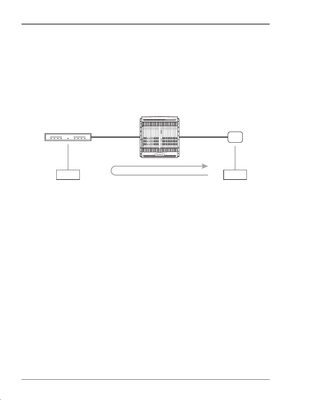
OAM Alarms and Loopbacks
ATM Switch to Modem Segment or End-to-End Loopback
The ATM switch to modem segment or end-to-end loopback test originates and terminates at
an ATM switch (point C). Th e loopback target or des tination is the modem (poi nt A), as shown
in the figure below. The loopback verifies a PVC from an ATM switch through to the modem.
In this test that originates at the ATM switch, the Avidia system is a passive ATM device; that
is, it simply passes the OAM F4 or F5 flow test cells, generated by the ATM switch,
transparently to the modem.
Avidia System
Megabit Modem
MEGABITMODEM
Point A
OAM Segment or End-to-End Loopback
ATM LinkADSL Loop
ATM
Switch
Point C
To perform this test, the user must be familiar with the OAM commands for the ATM switch.
The user must specify
the:
• VPI/VCI for an OAM F5 flow VCC or VPI only for an OAM F4 flow VPC (for the test
which is sent to the Avidia-to-switch interface)
• destination or target Location ID address (as defined at Point A) for an OAM loopback may
be required by some ATM switches (the modem does not have a Location ID so you can
leave the Destination Location ID as a default value if that value is different than the OAM
Location ID for the Avidia system)
64 Avidia System Configu rati on and Management User Manual
Page 91

Chapter 3: Applications and Config uration Overview
ATM Switch to Avidia Line Card Segment Loopback
The ATM switch to Avidia line card segment loopback originates and terminates at the source
ATM switch (point C). The loopback target or destination is the Avidia line card (point B),
as shown in the figure below
• VPI/VCI for an OAM F5 flow VCC or VPI only for an OAM F4 flow VPC
• OAM Destination Location ID for the Avidia system
Avidia System
. At the ATM switch, the user must specify for this test the:
ATM Link
OAM Segment Loopback
Point B - line card
ATM
Switch
Point C
ATM Node to Modem Segment or End-to-End Loopback
The ATM node (beyond the ATM switch) to modem segment or end-to-end loopback test
originates and terminates at an ATM node (point D). The loopback target or destination is
the modem (point A), as shown in the figure below. The loopback verifies a PVC from an
ATM node through to the modem. In this test that originates at the ATM node, the Avidia
system is a passive ATM device; that is, it simply passes the OAM F4 or F5 flow test cells,
generated by the ATM switch, transparently to modem.
Avidia System
Megabit Modem
MEGABITMODEM
ATM LinkADSL Loop
ATM
Switch
ATM node
Point A
Avidia System Configuration and Management User Manual 65
OAM Segment or End-to-End Loopback
Point D
Page 92
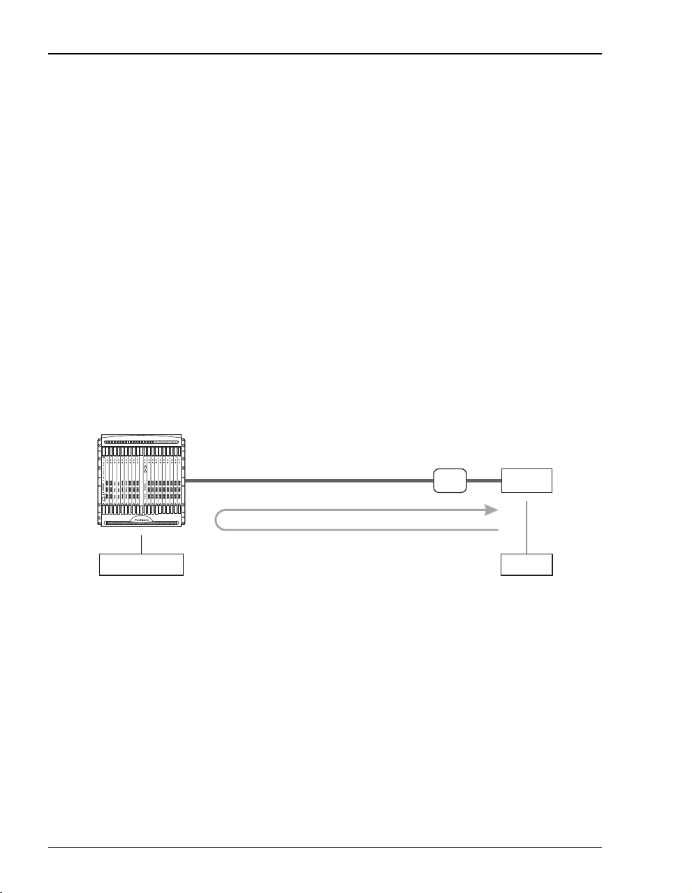
OAM Alarms and Loopbacks
To perform this test, the user must be familiar with the OAM commands for the ATM node.
The user must specify
the:
• VPI/VCI for an OAM F5 flow VCC or VPI only for an OAM F4 flow VPC
• destination or target Location ID address (as defined at Point A) for an OAM loopback may
be required by some ATM nodes (the modem does not have a Location ID, so leave the
Destination Location ID as a default value if that value is different than the OAM Location
ID for the Avidia system)
ATM Node to Avidia Line Card Segment Loopback
The ATM node (beyond the ATM switch) to Avidia line card segment loopback originates
and terminates at the source
Avidia line card (point B), as shown in the figure below. At the ATM node, the user must specify
for this test the:
• VPI/VCI for an OAM F5 flow VCC or VPI only for an OAM F4 flow VPC
• OAM Destination Location ID for the Avidia system
Avidia System
ATM node (point D). The loopback target or destination is the
ATM Link
OAM Segment Loopback
Point B - line card
66 Avidia System Configu rati on and Management User Manual
ATM
Switch
ATM node
Point D
Page 93

Chapter 3: Applications and Config uration Overview
Avidia Line Card to Modem End-to-End Loopback
The ADSL mo dems (Megabit Modem 700 F, 600F, and 500L software versions 2.6 a nd later)
support F5 flow OAM loopback s. (Megabit Modem 700F, 600F , and 500L software vers ion 2.7
and earlier do not support F4 flow loopback for VPCs .) Since an xDSL modem terminates ATM
service, the modem automatically loops back any OAM loopback cells it receives on any
configured PVC. The modem does not require additional configuration or addressing (such as
an OAM Location ID address) to respond to OAM loopback test cells.
The figure below shows a simple Avidia line card to modem OAM end-to-end loopback. The
end-to-end test is run between an ATM line card and an ADSL modem (Megabit Modem 700F,
600F, or 500L). The modem must have at least one user session (PVC) defined and active.
Depending on the model of the modem, the session could be either PPP (Megabit Modem 700F,
600F, or 500L) or bridging/routing (Megabit Modem 700F only).
Avidia System
Megabit Modem
MEGABITMODEM
Point A
ADSL Loop
OAM End-to-End Loopback
Point B - line card
In the loopback example shown abov e, the OAM test cells o riginate and terminate at the sour ce
Avidia ATM line card (point B). The modem (point A), which is the target or destination device,
does not generate any OAM cells. The modem loops back OAM test cells to the originating or
source device (point B).
Configure OAM loopbacks to run on each separately defined and active PVC for the Megabit
Modem 700F and 600F since these modems support multiple simultaneously active PVCs.
The Megabit Modem 700F supports up to 32 simultaneously active PVCs. The Meg abit
Modem 600F supports up to three simultaneously active PVCs.
Avidia System Configuration and Management User Manual 67
Page 94

OAM Alarms and Loopbacks
Segment Loopback for a Subtended Avidia System
Multiple systems can be implemented, viewed, and managed as if they were one system.
This type of management is known as subtending. Avidia systems can subtend other
Avidia systems or Avidia systems can be subtended by other ATM devices, such as
ATM switches.
The user can manage or subtend a remote Avidia system using another Avidia system. One
possible link between the subtending Avidia system and the subtended or remote Avidia system
is an Avidia OC-3 line card (AV311, AV312, or AV313). The subtending Avidia system (point
B) originates and terminates the OAM loopback, as shown in the figure below. The loopback
target or destination is the subtended Avidia system (point C). The loopback test for this
subtended segment functions in much th e same way as a segment OAM loopback is performed
between an Avidia system and a modem (page 62). Enter the OAM Location ID for the
subtended system (point C) as the OAM Destination Location ID.
Avidia System Subtended Avidia System
ATM Link
OAM Segment Loopback
Point B
Point C
See “Subtending Multiple Systems” on page 45 for more information about subtending
systems.
After Running Loopbacks
After loopbacks are completed, check for the following results:
• Examine the OAM Loopback status to see if the test successfully completed or failed.
• If the test failed, use OAM to isolate the failing ATM link, PVC, or component. Also check
the Avidia loop and link performance statistics and interface counters.
• Take corrective action, as required, and repeat the OAM test until it runs successfully.
• When initiating the loopback test from an ATM switch, use the documentation sup plied
with that product for OAM testing procedures.
68 Avidia System Configu rati on and Management User Manual
Page 95

Chapter 3: Applications and Config uration Overview
AVIDIA ALARM MANAGER
An Alarm Manager stores all the alarm information for the entire system. The alarm manage r is
stored on the management card, however each individual card installed in the system also stor es
alarm information for its own ports. If you replace the managemen t card, the new managem ent
card retrieves the current alarm information from the individual cards to build a new alarm
database.
CONFIGURING AVIDIA SYSTEM INFORMATION
To enable access to the Avidia Web Interface, you must first configure the management card IP
address and subnet mask using the command-line interface. To simplify network managemen t,
you should also configure:
• system identification information
• trap generation
• boot file information
• system date and time
• default gateway
• trap receivers
• community strings (only configurable using the command-line interface)
Avidia System Configuration and Management User Manual 69
Page 96

Setting Up Connections
SETTING UP CONNECTIONS
The following sections list the tasks you need to perform to set up service for these interfaces.
DS1 Line/Management Combination Card
The DS1 line/management card acts as both a line and an AMC card, providing configuration
and management support for the Avidia system as well as eight DS1 uplinks to transm it
subscriber traffic as ATM cells.
You must configure both DS1 and system parameters when configuring the DS1
line/management card. You cannot directly configure a DS1 line/management card using
StarGazer. Instead, the Avidia system containing the DS1 line/management card must first be
subtended to an AV8000 or AV3000 system (see “Subtending Multiple Systems” on page 45
for information on configuring subtending). Once the system is subtended, you can use in-band
management to configure the DS1 and management parameters.
There are three steps in configuring a DS1 line/management card:
1 Subtend the system containing the DS1 line/management card to an Avidia 8000 or 3000
(see “Subtending Multiple Systems” on page 45).
2 Configure the system boot parameters, trap enablers, and identifiers for the system in which
the DS1 line/management card resides (see “Subtending Multiple Systems” on page 45).
3 Configure the DS1 ports on the DS1 line/management card. See “Configuring DS1
Service” on page 143 (command-line interface) or “Configuring DS1 Servi ce” on page 417
(Web interface).
70 Avidia System Configu rati on and Management User Manual
Page 97

Chapter 3: Applications and Config uration Overview
Frame-based Services
Set up service for either an I DSL or SDSL frame-based car d using on e of the following s ections.
SDSL Frame Service
The following shows the configuration process for setting up SDSL frame-based service.
• Create one or more SDSL frame line profiles. See “Configuring SDSL Frame Line
Profiles” on pag e 111 (command-line interface) or “Configuring SDSL Frame Line
Profiles” on pag e 393 (Web interface).
• Create one or more SDSL frame alarm profiles. See “Configuring SDSL Frame Alarm
Profiles” on pag e 114 (command-line interface) or “Configuring SDSL Frame Alarm
Profiles” on pag e 395 (Web interface).
• Provision service for the SDSL frame card. Configure the ports (includes selecting the
SDSL frame line profile and SDSL frame alarm profile for each port). See “Configuring
SDSL Frame Service” on page 117 (command-line interface) or “Configuring SDSL
Frame Service” on page 397 (Web interface).
• Create the VCC through the Avidia system (from the line card to the SDSL frame-based
card). See “Configuring PVCCs” on page 170 (command-line interface) or “Configuring
PVPCs” on page 433 (Web interface) for more information.
• Configure a session to set the service and encapsulation types for the VCC. The available
encapsulation types depend upon the service type you select and both must match the
modem encapsulation type. See “Configuring Bridging and Routing Sessions” on page 228
(command-line interface) or “Configuring Bridging and Routin g Sessions” on page 486
(Web interface) for more information.
Avidia System Configuration and Management User Manual 71
Page 98

Setting Up Connections
IDSL Service
Do the following to configure IDSL frame-based services:
• Create one or more IDSL line profiles. See “Configur ing IDSL Line Pro files” on page 127
(command-line interface) or “Configuring IDSL Line Profiles” on page 406 (Web
interface).
• Create one or more IDSL alarm profiles. See “Configuring IDSL Alarm Profiles” on
page 130 (command-line interface) or “Configuring IDSL Alarm Profiles” on page 408
(Web interface).
• Configure service for the IDSL frame card ports, including selecting the IDSL card transmit
clock source. See “Configuring IDSL Service” on page 133 (command-line interface) or
“Configuring IDSL Service” on page 411 (Web interface).
• Select either ATM VCC or Frame Relay to match the modem. For example, if you are using
a WebRamp 450i modem configured with Ramp1483 service type, configure an ATM
VCC using ramp1483 encapsu la tio n type. If the WebRamp 450i modem is config ured for
Frame Relay, you will need to set up Frame Relay service. See “Frame Relay
Transmission” on page 26 for information on configuring Frame Relay service.
72 Avidia System Configu rati on and Management User Manual
Page 99

Chapter 3: Applications and Config uration Overview
Connection Type Use This Setup
Frame Relay Select this connection type for modems using Frame Relay.
Step 1 Configure the frame relay link for each port, which involves setting the LMI (Local
Management Interface) parameters. The LMI type defines the method of
exchanging status information between the customer device and the network. The
available LMI types are:
• LMI Rev-1
• ITU 0.933 Annex-A
• ANSI T1 617 Annex-D
• no LMI support
Step 2 Configure the FRF.5 or FRF.8 circuit for each port. This includes creating the cross
connect through the Avidia system (from the line card to the IDSL frame card), and
configuring cell loss priority, congestion control, and the traffic type. The available
traffic types are:
• ubr (Unspecified Bit Rate)—This is a best-effort class of traffic that is best
suited for LAN. When network congestion occurs, the data is stored in a buffer
until it can be sent.
• cbr (Constant Bit Rate)—This traffic class carries a guaranteed constant
bandwidth. It is best suited for applications that require fixed bandwidth, such
as uncompressed voice, video, and circuit emulation. CBR is a Quality of
Service class defined by the ATM Forum for ATM network.
• nrt-vbr (non-real-time Variable Bit Rate)—This traffic class carries variable
bandwidth. It is well suited for data services such as frame relay over ATM
which requires guaranteed bandwidth and lower Quality of Service. It is not well
suited for LAN traffic due to the unpredictability of LAN traffic burst size.
• rt-vbr (real-time Variable Bit Rate)—This traffic class carries a variable
bandwidth. It is well suited for real-time services such as compressed voice and
video which require stringent cell transfer latency and less bursty traffic. It is
not well suited for LAN traffic due to the unpredictability of LAN traffic burst
size.
ATM VCC
Select this connection type for modems that are not using Frame Relay but other
protocols such as PPP.
Step 3
To connect to modems not configured with the frame relay protocol, add an ATM
VCC (see “Configuring PVCCs” on page 170 for the command-line interface or
“Configuring PVPCs” on page 433 for the Web interface). Adding a VCC includes
selecting the channel parameters (specific IDSL card, the port, the service type,
and the encapsulation method). The available encapsulation types depend upon
the service type you select and both must match the modem encapsulation type.
Avidia System Configuration and Management User Manual 73
Page 100

Setting Up Connections
Cell-based Services
Set up service for either an ADSL or SDSL cell-based card using one of the fo llowing sections.
ADSL
The following shows the configuration process for setting up ADSL cell- based service.
• Create one or more ADSL line profiles. See “Configuring ADSL Line Profiles” on
page 100 (command-line interface) or “Configuring ADSL Line Profiles” on page 386
(Web interface).
• Create one or more ADSL alarm profiles. See “Configuring ADSL Alarm Profiles” on
page 104 (command-line interface) or “Configuring ADSL Alarm Profiles” on page 388
(Web interface).
• Provision service for the ADSL card. Configure the ports, including assigning th e ADSL
line and alarm profiles to ADSL ports. See “Configuring ADSL Service” on page 109
(command-line interface) or “Configuring ADSL Service” on page 391 (Web interface).
• Create the cross connect through the Avidia system from the line card to the ADSL
cell-based card. See “Configuring PVCCs” on page 170 (command-line interface) or
“Configuring PVPCs” on page 433 (Web interface) for more information.
Cell-based SDSL
To configure SDSL cell service, you must:
• configure SDSL cell line profiles. See “Configuring SDSL Cell Line Profiles” on page 119
(command-line interface) or “Configuring SDSL Cell Line Profiles” on page 399 (Web
interface).
• configure SDSL cell alarm profiles. See “Configuring SDSL Cell Alarm Profiles” on
page 121 (command-line interface) or “Configuring SDSL Cell Alarm Profiles” on
page 401 (Web interface).
• configure SDSL cell ports. See “Configuring SDSL Cell Service” on page 124
(command-line interface) or “Configuring SDSL Cell Service” on page 404 (Web
interface).
• establish ATM connections between ports across the Avidia chassis. See “Configuring
PVCCs” on page 170 (command-line interface) or “Configuring PVPCs” on page 433
(Web interface) for more information.
74 Avidia System Configu rati on and Management User Manual
 Loading...