

Page 1

ADCP-61-743 • Issue 3 • September 2004
Content Page
1 DESCRIPTION ........................................................................................................................................4
2 INSTALLATION ......................................................................................................................................6
3 LED CHECK ......................................................................................................................................... 10
4 FRONT PANEL OPERATION ...................................................................................................................... 11
5 CONFIGURATION .................................................................................................................................. 12
6 TL1 COMMANDS................................................................................................................................... 28
7 SPECIFICATIONS .................................................................................................................................. 29
8 CUSTOMER INFORMATION AND ASSISTANCE ............................................................................................... 30
INTRODUCTION
Soneplex
®
Remote Test Access Unit (RTAU)
User Manual)
1.1 DS3 MUX Compatibility .....................................................................................................................6
2.1 Initial Installation ............................................................................................................................7
2.1.1 Damaged Pins......................................................................................................................... 8
2.2 Maintenance Installation (Existing System) .............................................................................................9
This manual describes and provides installation procedures for the Remote Test Access Unit
(RTAU) module used in the Soneplex Broadband System (MPU V5.3 and SCU V3.0 or later).
Revision History
ISSUE DATE REASON FOR CHANGE
Issue 1 06/1999 Original
Issue 2 04/2000 Add DS3 MUX compatibility and SCU 3.0 or later support.
Issue 3 09/2004 Technically updated 2. Installation, 3. LED Check, and 8. Customer Information and Assistance
Trademark Information
ADC and ADC Telecommunications are registered trademarks of ADC Telecommunications, Inc.
Soneplex is a registered trademark of ADC Telecommunications, Inc.
sections.
1304058 Page 1
2004, ADC Telecommunications, Inc.
Page 2
ADCP-61-743 • Issue 3 • September 2004
Related Publications
Listed below are related manuals and their publication numbers. Copies of these publications
can be ordered by contacting the ADC Technical Assistance Center at 1-800-366-3891.
Title ADCP Number
Soneplex Broadband System Description, Design, and Application Manual (V5) ADCP-61-472
Soneplex Broadband System Operation and Maintenance Manual (V5) ADCP-61-471
Soneplex DS3 MUX Module Installation Instructions ADCP-61-742
Soneplex System Installation Manual LTPS-UM-8010
Soneplex Shelf Controller Unit (V4.1) User Manual LTPS-UM-8031
Admonishments
Important safety admonishments are used throughout this manual to warn of possible hazards
to persons or equipment. An admonishment identifies a possible hazard and then explains what
may happen if the hazard is not avoided. The admonishments — in the form of Dangers,
Warnings, and Cautions — must be followed at all times. These warnings are flagged by use of
the triangular alert icon (seen below), and are listed in descending order of severity of injury or
damage and likelihood of occurrence.
Danger: Danger is used to indicate the presence of a hazard that will cause severe personal
injury, death, or substantial property damage if the hazard is not avoided.
Warning: Warning is used to indicate the presence of a hazard that can cause severe personal
injury, death, or substantial property damage if the hazard is not avoided.
Caution: Caution is used to indicate the presence of a hazard that will or can cause minor
personal injury or property damage if the hazard is not avoided.
General Safety Precautions
Caution: Electronic modules can be damaged by electrostatic discharge (ESD). Before
handling modules, wear an anti-static discharge wrist strap to prevent damage to electronic
components. Place modules in anti-static packing material when transporting or storing. When
working on modules, always place them on an approved anti-static mat that is electrically
grounded.
Page 2
2004, ADC Telecommunications, Inc.
Page 3

FCC Compliance Statement
The Remote Test Access Unit has been certified to comply with the requirements for Class A
computing devices per part 15 of the FCC regulations.
ADCP-61-743 • Issue 3 • September 2004
Warning: This equipment generates, uses, and can radiate radio frequency energy and if not
installed and used in accordance with the instruction manual, may cause interference to radio
communications. It has been tested and found to comply with limits for a Class A digital device
pursuant to Subpart A of Part 15 of FCC Rules, which are designed to provide reasonable
protection against such interference when operated in a commercial environment. Operation
of this equipment in a residential area is likely to cause interference to TV and radio reception
in which case the user, at their own expense, will be required to take whatever measures may
be required to correct the interference.
This equipment does not exceed Class A limits for radio emission for digital apparatus, set out in
the radio interference regulation of the authorization methods of Industry Canada. Operation in
a residential area may cause unacceptable interference to TV and radio reception requiring the
owner or operator to take whatever steps are necessary to correct the interference.
Certification
The Soneplex Broadband system is compliant with UL 1459.
Standards
ANSI T1.403-1997 Carrier to Customer Installation: DS1 Metallic Interface, 1997
TR-NPL-000054 High-Capacity Digital Service (1.544 Mbps) Interface General
Requirements for End Users, Issue 1, April 1989
© 2004, ADC Telecommunications, Inc.
Page 3
Page 4

ADCP-61-743 • Issue 3 • September 2004
1 DESCRIPTION
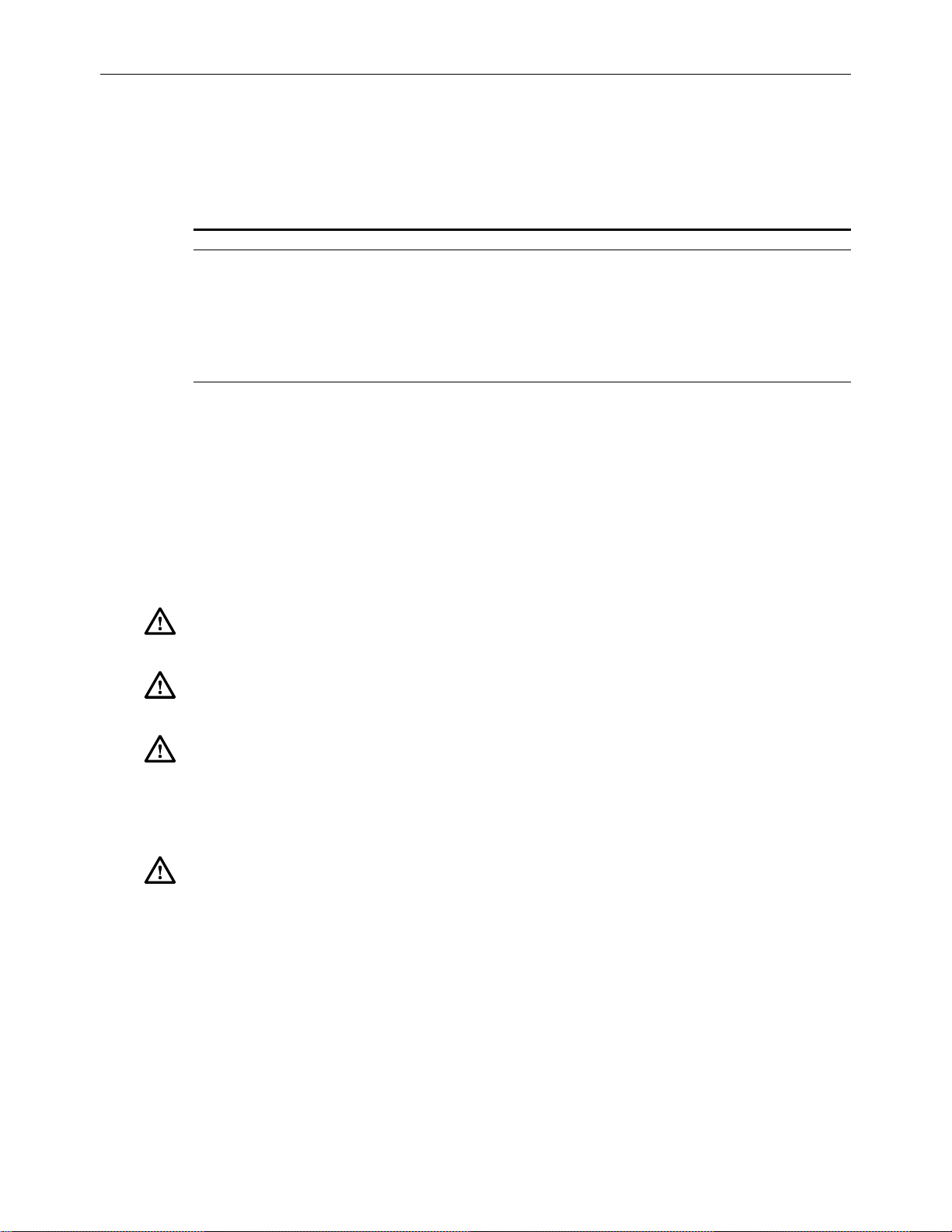
The Remote Test Access Unit (RTAU) (Figure 1) provides maintenance functionality for
monitoring and intrusive test access to the DS1 channels in the chassis between the DS3 MUX
and the low speed distribution modules (DLX, HLXC, ODS2, and RLX). The RTAU requires
no periodic maintenance. It requires the Version D1 or later DS3 MUX module and MPU
Version 5.3 or SCU Version 3.0 or later system software to be functional in the Soneplex
Broadband System for DS3 applications. If an earlier version of MPU software is used, the
RTAU will appear as a blank slot on the Craft Interface’s Inventory Status screen. Earlier
versions of the SCU software will not display the TAU slot.
The RTAU has the following features:
• Access supervision for intrusive testing (i.e., monitor access, split access for both A and
B transmission paths, and loop access for both A and B transmission paths).
• Stress testing of any circuit within the system via the Internal Test Signal Generation
feature. Many DS1 networks are tested by passing repeating sequences (patterns) of
logical ones and zeros through the network, also known as stress test patterns. As the test
patterns are applied to the circuit, they are compared with the original pattern to
determine if any errors are introduced. QRS (Quasi Random Signal) is one of the test
patterns supported. (QRS conforms to TR-NPL-000054.)
• Capable of inserting bit errors at a specified rate or as single errors or burst errors to the
DS1 circuit being tested.
• Ability to monitor (intrusively or non-intrusively) the DS1 circuit being tested.
• User control through the Craft Interface or via the TL1 interface.
• Access to the DS1 through front panel bantam jacks or through the internal test signal
generator. This control is configurable through the Craft Interface.
• Supports the Building Integrated Timing Supply (BITS) primary interface through the
wire wrap pins on the back of the Soneplex Broadband chassis. If a valid BITS signal is
applied to the Broadband chassis, the RTAU will automatically switch over to the BITS
primary interface and use the recovered clock for timing.
Note: The BITS secondary interface on the Soneplex Broadband chassis is not supported
by the RTAU.
Page 4
2004, ADC Telecommunications, Inc.
Page 5
RTAU
STATUS
B8ZS
AMI
LINE CODE
INTRUSIVE
TEST
ADCP-61-743 • Issue 3 • September 2004
BIPOLAR
ACCESS
D
S
RX
1
TX
11897-A
Figure 1. Remote Test Access Unit (RTAU) Module
© 2004, ADC Telecommunications, Inc.
Page 5
Page 6

ADCP-61-743 • Issue 3 • September 2004
1.1 DS3 MUX Compatibility
Refer to Table 1 for compatibility information for DS3 MUXs, test access units, and MPU/SCU
software versions.
Table 1. DS3 MUX, TAU/RTAU, and MPU/SCU Software Compatibility
DS3 MUX TYPE
C1 TAU 5.1.1 or later 2.5 or later TAU
C1 RTAU 5.1.1 or later 2.0 or later NO TEST ACCESS
D1 TAU 5.1.1 or later 2.5 or later TAU
D1 RTAU 5.2 or earlier 2.5 or earlier NO TEST ACCESS
D1 RTAU 5.3 3.0 or later RTAU
G1 TAU 5.1.1 or later 2.5 or later TAU
G1 RTAU 5.2 or earlier 2.5 or earlier NO TEST ACCESS
G1 RTAU 5.3 3.0 or later RTAU
Refer to the Soneplex System Operation and Maintenance Manual listed under Related
Publications at the beginning of this manual for more information.
2 INSTALLATION
There are two installation procedures:
• Initial Installation - This installation procedure applies to the first time an IBBC shelf
will be populated with a RTAU module.
TEST ACCESS
UNIT TYPE
MPU SOFTWARE
VERSION
SCU SOFTWARE
VERSION
FUNCTIONALITY
• Maintenance Installation (Existing System) - This installation procedure applies to an
IBBC shelf that has already been populated with a RTAU module.
Please follow the appropriate procedure per your system configuration.
Page 6
2004, ADC Telecommunications, Inc.
Page 7
2.1 Initial Installation
This installation procedure applies to the first time an IBBC shelf will be populated with
a RTAU module. If the IBBC shelf has already been populated with a RTAU module, go
to 2.2. Maintenance Installation (Existing System).
Installation consists of unpacking and installing the RTAU module, and verifying that it is
functioning properly. Use the following procedure to install a RTAU module:
ADCP-61-743 • Issue 3 • September 2004
Caution: Electronic modules can be damaged by static electrical discharge. Before handling
modules, wear an anti-static discharge wrist strap to prevent damage to electronic
components. Place modules in anti-static packing material when transporting or storing. When
working on modules, always place them on an approved anti-static mat that is electrically
grounded.
Warning: If the RTAU module is improperly installed, damage can be caused to the system.
Be careful when inserting the RTAU module into a new chassis.
Caution must be used to prevent bending pins when inserting modules into a new IBBC shelf.
Once a module has been successfully seated in the connector, it “trains” the pins and aligns
them to the modules connector greatly reducing the chances of bending pins on subsequent
insertions. The following procedure outlines a method to mitigate the risk on a new shelf
installation.
1. Open the front cover of the Soneplex Broadband system.
2. Open the shipping carton and carefully unpack the RTAU module from its protective
packing material.
3. Once the Soneplex shelf has been installed and powered up:
a. Remove both-48V A and B side fuses (and “pilot” fuses if used).
b. Inspect the RTAU slots for bent or misaligned pins.
c. If pins are not bent, continue to the next step. If pins are bent, refer to 2.1.1 Damaged
Pins section.
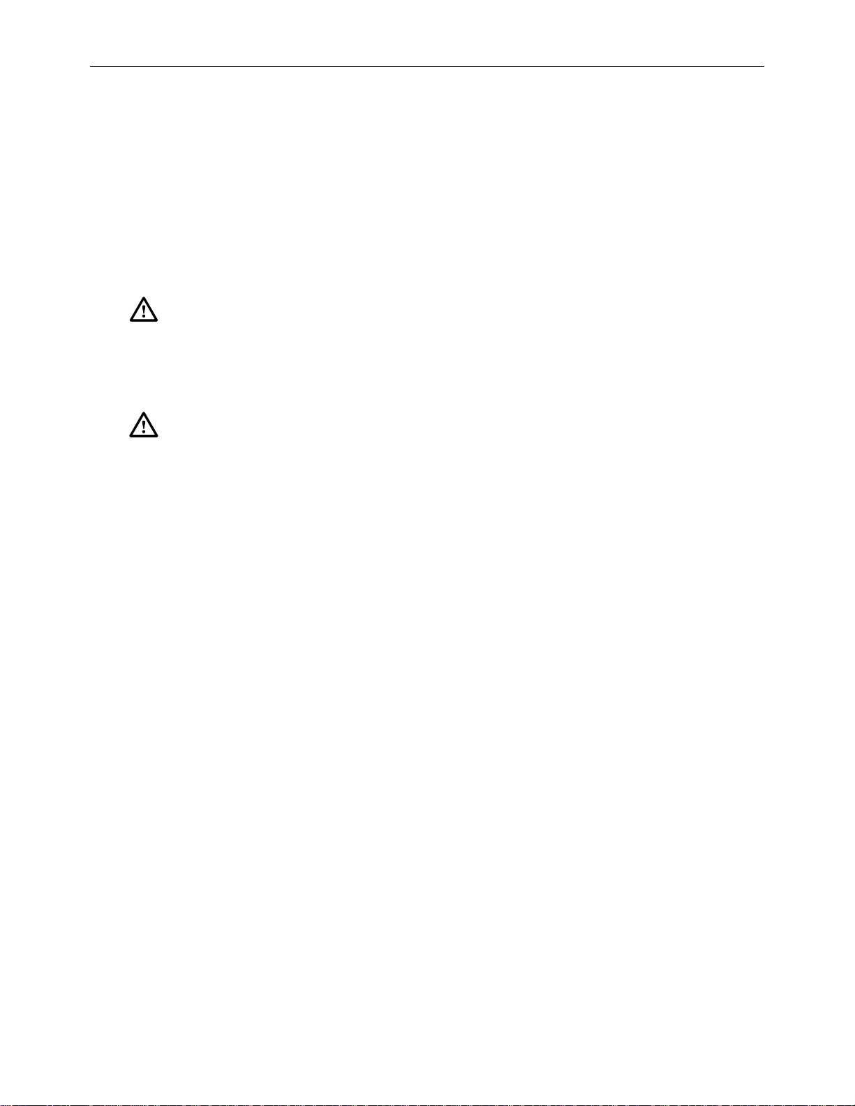
4. With shelf unpowered, refer to the chassis marking above the module slot (Figure 2) to
install the RTAU module in the full-height slot labeled TAU.
© 2004, ADC Telecommunications, Inc.
Page 7
Page 8
ADCP-61-743 • Issue 3 • September 2004
HSW
HSP
MXPMXW
TAU
RTAU
STATUS
STATUS
LPBK
LPBK
ENABLE
ONLINE
DS3 FAIL
LOCKOUT
APS
APS
FORCE
LMPTST/
APS
RESET
STATUS
ENABLE
B8ZS
AMI
ONLINE
LINE CODE
INTRUSIVE
DS3 FAIL
TEST
LOCKOUT
FORCE
LMPTST/
APS
RX
D
S
1
TX
RESET
1-31-1 2-1 2-3 3-1 3-3 4-1 4-3 5-1 5-3 6-1 6-3 7-1 7-3
1-41-2 2-2 2-4 3-2 3-4 4-2 4-4 5-2 5-4 6-2 6-4 7-2 7-4
APU
DISP RMT
LMPTST
APU
STATUS
C
R
A
F
T
RESET
SCU
CR
MJ
MN
ACO
PWR
HSKP
RMT
ALM
14185-A
RTAU MODULE
Figure 2. RTAU Mounting Position in the Soneplex Broadband
5. Align the module edges of the RTAU with the mounting slot module guides. Use the
injectors to seat the module in the chassis.
6. Remove the RTAU module.
7. Inspect the backplane connector for bent pins.
8. If pins are not bent, continue to the next step. If pins are bent, refer to 2.1.1 Damaged
Pins section.
9. Re-install the RTAU module.
10. With the RTAU module installed, power up the shelf one fuse at a time.
a. Install the -48V A fuse.
b. Install the -48V B fuse.
Refer to 8. Customer Information and Assistance, if needed.
2.1.1 Damaged Pins
The pins used in the back plane connector should not be straightened after they have been
deflected more than 10 degrees from vertical as they will “work harden” and break at the
bend. Bent pins must be removed and replaced using special tools and is not
recommended as a field repair. Remove shelf with damaged pins and contact ADC for
replacement. Refer to 8. Customer Information and Assistance.
Page 8
2004, ADC Telecommunications, Inc.
Page 9
2.2 Maintenance Installation (Existing System)
Replacement of the RTAU module in existing IBBC shelves should follow normal
maintenance procedures. Since a module has already been in service in the affected slot, the
backplane pins will have been trained into alignment with subsequent replacement modules. If
excessive resistance is encountered upon insertion, remove the module and inspect for
misalignment or obstructions.
This procedure assumes that the IBBC shelf has already been populated with a RTAU
module. If this is the first time that the IBBC shelf has been populated with a RTAU
module, go to 2.1 Initial Installation.
Installation consists of unpacking and installing the RTAU module, and verifying that it is
functioning properly. Use this procedure to install a RTAU module.
ADCP-61-743 • Issue 3 • September 2004
Warning: To prevent electrical shock, never install equipment in a wet location or during a
lightning storm. When installing or modifying telephone lines, disconnect lines at the network
interface before working with uninsulated lines or terminals.
Caution: Electronic modules can be damaged by electrostatic discharge (ESD). Before
handling modules, wear an anti-static discharge wrist strap to prevent damage to electronic
components. Place modules in anti-static packing material when transporting or storing. When
working on modules, always place them on an approved anti-static mat that is electrically
grounded.
1. Open the front cover of the Soneplex Broadband (V5) chassis.
2. Open the shipping carton and carefully unpack the RTAU module from its protective
packing material. Inspect the module for damage
3. Refer to chassis markings above the module slot (Figure 2) to install the RTAU module
in the full-height slot marked TAU.
4. Align the module edges of the RTAU with the mounting slot module guides. Use the
injectors to seat the module in the chassis. If there is excessive resistance, remove the
module and check for obstructions or improper alignment.
© 2004, ADC Telecommunications, Inc.
Page 9
Page 10

ADCP-61-743 • Issue 3 • September 2004
3 LED CHECK
1. When the RTAU module (Figure 3) is seated, the STATUS LED will be lit red for
approximately 5 seconds. All LEDs will then flash yellow, and then the STATUS LED
will be lit green. If the STATUS LED is not lit green after 10 seconds, replace the
module. Refer to 2.2 Maintenance Installation (Existing System).
RTAU
STATUS
B8ZS
AMI
LINE CODE
INTRUSIVE
TEST
BIPOLAR
ACCESS
RX
D
S
TX
1
12693-B
Figure 3. RTAU Front Panel
Page 10
2004, ADC Telecommunications, Inc.
Page 11

4 FRONT PANEL OPERATION
All controls and indicators of the RTAU including the jack accesses for a selected DS1 signal
are located on the front panel (Figure 3). The controls and indicators are described in Table 2.
INDICATOR COLOR DESCRIPTION
STATUS Red Module failure.
Yellow LED test.
Green Module operating normally.
B8ZS / AMI Green Indicates that the user has selected B8ZS line code for the bipolar
Yellow Indicates that the user has selected AMI line code for the bipolar
Off Indicates that the user has selected the internal signal monitor
Intrusive Test Yellow LED test.
Green Indicates that the selected test mode of the RTAU is intrusive.
Off No intrusive testing in progress.
SWITCH DESCRIPTION
LINE CODE This is a pushbutton switch that toggles the DS1 interface between B8ZS, AMI, or
the internal signal monitor generator at the RTAU. When B8ZS has been selected,
the B8ZS/AMI LED will turn green; when AMI has been selected, the B8ZS/AMI
LED will turn yellow; when the internal signal monitor generator at the RTAU is
selected, the B8ZS/AMI LED will turn off. Using this switch overrides the Craft
Interface RTAU Line Code field setting.
BIPOLAR
ACCESS JACKS DESCRIPTION
ADCP-61-743 • Issue 3 • September 2004
Table 2. RTAU Front Panel Description
interface.
interface.
generator at the RTAU.
DS1 RX Bantam jack connection from DS1 receive to test equipment. Bipolar DS1 signals
from external test equipment can be applied to the RX jack for testing.
DS1 TX Bantam jack connection from DS1 transmit to test equipment. Bipolar DS1 signals
from external test equipment can be applied to the TX jack for testing.
Note: The DS1 RX and DS1 TX jacks may be used with 22 AWG Plastic Insulated
Cable (PIC) up to 655 feet in length. Access for drop or insert of DS1 signals
towards the network (DS3 interface) or toward the customer (DS1 distribution
modules) for monitoring and intrusive testing is configured through the Craft
Interface or the TL1 interface.
© 2004, ADC Telecommunications, Inc.
Page 11
Page 12

ADCP-61-743 • Issue 3 • September 2004
5 CONFIGURATION
Use this menu to view or edit the configuration for the RTAU module after it is installed in the
chassis. This menu can also be used to equip, provision, assign thresholds, and assign service
state.
Note: A “toggle” field type means the user can press the space bar to view and select the
next option that is described; or the user can press the “R” key to view and select the previous
option. An “input” field type means the user must type an entry in the field according to the
parameters described. A “fixed” field is locked and cannot be changed by the user.
Note: Edits can be made in the configuration database in one of two ways: 1) If the
complete field is highlighted, use the space bar to toggle forward or the “R” key to
reverse toggle through the options for that field. 2) If only the first space or the field is
highlighted, type in the data that applies to that field.
Note: Edits can be saved into the configuration database after each change is made in
one of two ways: 1) Press an arrow key and then Enter or Return once; or 2) Press Enter
or Return twice after all selections and entries are made in the screen but before leaving
the screen. If the entries have been accepted, a message “Configuration Successful…
Press Any Key To Continue” will appear on the screen.
Note: Press CONTROL-A for help information on moving around and editing fields.
Note: The RTAU’s status can also be displayed using the Shelf Status screen, where the
letter “R” in the TAU slot column means an RTAU is present. Refer to the Soneplex
System Operation and Maintenance Manual listed under Related Publications at the
beginning of this manual for more information on the Shelf Status screen.
Note: Be sure to configure the line card to be tested before setting up test access.
1. Refer to Figure 3 (shown previously). Check that the STATUS LED on the front panel of
the RTAU module is green, indicating that the module is operating normally.
2. Log on to the Craft Interface. If you are unfamiliar with the log on procedure, refer to the
Soneplex System Operation and Maintenance Manual listed under Related Publications at
the beginning of this manual for more information.
3. Use the arrow or number keys to select System Maintenance from the Main Menu. Press
Enter or Return. The System Maintenance menu will appear as shown in Figure 4.
4. Use the arrow or keyboard keys to select Test Access Unit Commands from the System
Maintenance menu. Press Enter or Return. The RTAU Configuration menu will appear as
shown in Figure 5.
Note: The User Pattern Definition screen is not available for the MPU 5.3 or SCU V3.0
releases.
Page 12
2004, ADC Telecommunications, Inc.
Page 13

ADCP-61-743 • Issue 3 • September 2004
5. Use the arrow or number keys to select RTAU Setup and Control from the RTAU
Configuration menu. Press Enter or Return. The RTAU Setup and Control screen will
appear as shown in Figure 6.
Note: If the RTAU is not plugged into the chassis and the Test Access Unit Commands
selection is made from the System Maintenance menu, the Test Access Unit
Status/Commands screen will appear as shown in Figure 7. This screen cannot be
configured. However, if the TAU is plugged into the chassis and the Test Access Unit
Commands selection is made from the System Maintenance menu, the Test Access Unit
Status/Commands screen will appear and can be configured.
© 2004, ADC Telecommunications, Inc.
Page 13
Page 14

ADCP-61-743 • Issue 3 • September 2004
1. Force/APS Commands
2. Reset/LED Test Commands
3. Execute ACO (Alarm Cutoff)
4. Loopback Status/Commands
5. Display Inventory
6. Display Circuit IDs
7. SCU-860 Data Transfer Commands
8. Trouble Isolation
9. Metallic Testing Screen (for IBBCMLQ only)
A. Test Access Unit Commands
SYSTEM MAINTENANCE
Press CONTROL-A For Assistance
Figure 4. System Maintenance Menu
RTAU CONFIGURATION
1. RTAU Setup and Control
2. User Pattern Definition
Press CONTROL-A For Assistance
6. Starting at the top of Table 3 and working your way to the bottom, configure RTAU
fields. Use the arrow keys to move from field to field.
Page 14
2004, ADC Telecommunications, Inc.
Figure 5. RTAU Configuration Menu
Page 15

ADCP-61-743 • Issue 3 • September 2004
7. Assign the selections by pressing Enter or Return.
RTAU SETUP AND CONTROL
EQUIPMENT SETUP
===============
Current User : NONE Test Circuit: 1-1
Line Code : INTERNAL Mode : DISABLE
SIGNAL GENERATOR SETUP
======================
Pattern Type : QRS #: ------------------------------- Frame Format : UNFRAMED
Loop Code : NONE #: ----------------
BIT ERROR SETUP Error Counts Status Elapsed Time
=============== ============ ====== ============
Error Count : 0 Data : F Sync: ES :
Error Rate : OFF BPV : P Sync: EFS:
Error Locn : NONE Frame: RAI :
CRC :
COFA :
Test Timeout : 60 Measurement : STOP
In Minutes
Press CONTROL-A For Assistance
Figure 6. RTAU Setup and Control Screen
(Showing Defaults for Screen With Line Code Field Set to INTERNAL)
TEST ACCESS UNIT STATUS/COMMANDS
Group: 1 DS1#: 1
Drop Direction Insert Direction
============== ================
Status :
Command :
TAU Present Status: NO
Press Control-A For Assistance
Figure 7. Test Access Unit Status/Commands Screen
(If there is a TAU in the chassis, the TAU Present Status: displays YES)
© 2004, ADC Telecommunications, Inc.
Page 15
Page 16

ADCP-61-743 • Issue 3 • September 2004
FIELD TYPE OPTIONS DESCRIPTION DEFAULT
EQUIPMENT SETUP FIELDS
Current User Toggle OVER VI E W : T h e Cu r r e n t U s e r f ie l d c a n o n l y b e
NONE The RTAU is not being used.
CRAFT The RTAU is being controlled via the Craft.
TL1 The RTAU is being controlled via the TL1
EM The RTAU is being controlled via the Element
Line Code Toggle O VE R V I EW : I f ex t e r n a l t e st e q u i p m e n t i s b e in g
INTERNAL Disables RTAU front panel bantam jacks for
B8ZS Enables Bipolar Eight-Zero Substitution line
AMI Enables Alternate Mark Inversion line code
Test Circuit Input 1-1, 1-2, 1-3, 1-4,
Table 3. RTAU Configuration Fields
2-1, 2-2, 2-3, 2-4,
3-1, 3-2, 3-3, 3-4,
4-1, 4-2, 4-3, 4-4,
5-1, 5-2, 5-3, 5-4,
6-1, 6-2, 6-3, 6-4,
7-1, 7-2, 7-3, 7-4
set to NONE or CRAFT from the Craft menu. If
the Current User field is set to NONE, the Mode
field is automatically set to DISABLE. However,
to change this field to CRAFT, the Mode field
must first be set to an option other than DISABLE.
At that point, the Current User field is
automatically set to CRAFT.
interface. This option cannot be enabled from
the Craft menu. When a “Connect Test Access
T1” command is issued, the Current User field
is automatically set to TL1.
Manager.
used, set the Line Code field to either AMI or
B8ZS. (External test equipment required: T-Berd
211 DS1 test set or equivalent that can generate a
T1 signal.) If the internal signal monitor and
signal generator of the RTAU is being used, set
the line code to INTERNAL. In addition, when
an intrusive test mode is selected and the line
code is set to INTERNAL, the signal generator
“Pattern Type” field defaults to QRS to transmit
an unframed QRSS signal.
test access. Selects internal TSG and SPD.
code through the Craft Interface.
through the Craft Interface.
Group and slot number to be dropped by the
DS3 MUX. The Test Circuit option can only be
changed if the value set in the Mode field is
DISABLE.
NONE
INTERNAL
1-1
Page 16
2004, ADC Telecommunications, Inc.
(continued)
Page 17

ADCP-61-743 • Issue 3 • September 2004
Table 3. RTAU Configuration Fields, continued
FIELD TYPE OPTIONS DESCRIPTION DEFAULT
EQUIPMENT SETUP FIELDS, continued
Mode Toggle OVERV I E W : V al i d access modes and the resulting
configurations are shown in Figure 8 (RTAU Test
Configuration Block Diagram), Figure 9 (MONF and
MONE), Figure 10 (SPLTB and SLPTA), Figure 11
(Typical Round-Robin Test Configuration), Figure 12
(Typical End Test Configuration), Figure 13 (SPLTF
and SLPTE), Figure 14 (Typical Point-to-Point Test
Configuration), Figure 15 (SPLTFL and SPLTEL),
and Figure 16 (LOOPF and LOOPE). In addition,
when the Mode field change is saved by pressing the
Enter or Return key, the MPU or SCU will instruct
the DS3 MUX to drop and insert the selected circuit.
DISABLE When DISABLE is selected, no monitor or split
access can take place. Setting the Mode field to
DISABLE also stops any measurement in
progress, as if the Measurement field (described
below) had been set to STOP. The tested circuit
will also be restored to normal operation.
MONE Non-intrusive monitor access to the A pair.
MONF Non-intrusive monitor access to the B pair.
SPLTA SPLTA mode indicates a split in the A
transmission path with a Test Signal Generator
(TSG) connected in the F direction, and a Signal
Presence Detector (SPD) connected to the signal
from the E direction.
SPLTB SPLTB mode indicates a split in the B
transmission path with a TSG connected in the E
direction and an SPD connected to the signal from
the F direction.
SPLTE SPLTE mode indicates a split in both the A and B
transmission paths. An SPD is connected to the line
incoming from the E direction and a TSG is
connected to the line outgoing to the E direction. The
line outgoing in the F direction is connected to a
QRSS source and the line incoming from the E
direction is terminated by the nominal characteristic
impedance of the line.
SPLTF SPLTF indicates a split in both the A and B
transmission paths with a TSG connected to the line
outgoing to the F direction and an SPD connected to
the line incoming from the F direction. The line
outgoing in the E direction is connected to a QRSS
source and the line incoming from the E direction is
terminated by the nominal characteristic impedance
of the line.
DISABLE
(continued)
© 2004, ADC Telecommunications, Inc.
Page 17
Page 18

ADCP-61-743 • Issue 3 • September 2004
FIELD TYPE OPTIONS DESCRIPTION DEFAULT
EQUIPMENT SETUP FIELDS, continued
Mode, continued SPLTEL SPLTEL indicates a split in both the A and B paths
Toggle SPLTFL SPLTFL indicates a split in both the A and B paths
LOOPE The LOOPE mode is a full split of both A and B
LOOPF The LOOPF mode is a full split of both A and B
SIGNAL GENERATOR SETUP FIELDS
Pattern Type Toggle OV E R V I E W: I f t h e d e s i r e d p a tt e r n t y p e i s n o t
QRS Quasi-Random Signal. QRS (220-1) is a 1,048,575-
Table 3. RTAU Configuration Fields, continued
and connects an SPD to the line incoming from the
E direction and a TSG to the line outgoing in the E
direction similar to SPLTE mode. The signal in the
F direction is looped back.
and connects an SPD to the line incoming from the
F direction and a TSG to the line outgoing in the F
direction similar to SPLTF mode. The signal in the
E direction is looped back.
transmissions paths. The incoming line in the E
direction is connected to the SPD and this line is
connected to the outgoing line in the E direction.
The circuit will be looped in one direction. The
outgoing line in the F direction (non-test direction)
will be connected to a QRSS source and the line
incoming from the F direction is terminated by the
nominal characteristic impedance of the line.
transmissions paths. The incoming line in the F
direction is connected to the SPD and this line is
connected to the outgoing line in the F direction. The
circuit will be looped in one direction. The outgoing
line in the E direction (non-test direction) will be
connected to a QRSS source and the line incoming
from the E direction is terminated by the nominal
characteristic impedance of the line.
QRS
available, select the User Code option to enter a
pattern 32 bits or less.
bit sequence generated by a 20-stage shift register
with feedback taken from the 17th and 20th stages.
The non-inverted output is taken from the 20th
stage, and an output bit is forced to be a ‘1’
whenever the next 14 bits are all 0’s. QRS is
typically used to verify continuity and to check
circuit performance in the presence of traffic-like
signals. Quasi-random Signal (QRS) is a signal
repeated every 1 to 24 bits as specified by the
Operation System (OS) application. QRS must
conform to the description in Bellcore TR-NPL-
000054.
Page 18
2004, ADC Telecommunications, Inc.
(continued)
Page 19

ADCP-61-743 • Issue 3 • September 2004
Table 3. RTAU Configuration Fields, continued
FIELD TYPE OPTIONS DESCRIPTION DEFAULT
SIGNAL GENERATOR SETUP FIELDS, CONTINUED
Pattern Type, continued Toggle 2^15-1 215-1 is a 32,767-bit, pseudo-random pattern
that generates a maximum of 14 sequential 0’s
and 15 sequential 1’s. The pattern provides a
maximum number of 0’s allowed for framed,
non-B8ZS testing. The pattern does not meet
the minimum 1’s density requirement.
2^23-1 223-1 is a 8,388,607-bit, pseudo-random
pattern that generates a maximum of 22
sequential 0’s and 23 sequential 1’s. The
pattern exceeds excess 0’s and does not meet
the minimum 1’s density requirements for T1
applications.
All Ones Test of T1 span line. The all-1’s pattern causes
the span line repeater to consume the maximum
amount of power. If the current powering the
span line is low, transmission errors may occur
due to the inter-symbol interference resulting
from the inability of a weak repeater power
supply to develop the energy necessary to
support the transmission of a long sequence of
1’s.
(Framed) All Zeros Used as a final confirmation that all network
elements in a circuit are properly optioned with
B8ZS for clear channel operation. The framed
all 0’s pattern consisting of a frame bit
followed by an all 0’s payload will only be
applied to circuit optioned with B8ZS for clear
channel operation.
3 in 24 Used to determine the ability of network
equipment to function properly when transporting
signal sequences containing both a maximum of
15 consecutive 0’s during periods of minimum
overall pulse density.
• Unframed = 1000 1000 1000 0000
0000 0000 1000 1000
• Framed = 0100 0100 0000 0000
0000 0100 0100 1000
2 in 8 Used in conjunction with the 1-in-8 pattern.
Useful when performing test to reveal the
presence of incorrectly-optioned AMI or B8ZS
equipment. Use of the 2-in-8 pattern will
confirm the circuits ability to support error-free
transmission.
• Unframed = 0100 0010 0100 0010
• Framed = 0100 0010 0100 0010
(continued)
© 2004, ADC Telecommunications, Inc.
Page 19
Page 20

ADCP-61-743 • Issue 3 • September 2004
FIELD TYPE OPTIONS DESCRIPTION DEFAULT
SIGNAL GENERATOR SETUP FIELDS, continued
Pattern Type, continued Toggle 1 in 8 Containing strings of 7 sequential 0’s. It is used
Daly Daly Pattern (Modified 55 Octet). This is useful
User Code For user-defined patterns of 32 bits or less, set the
Pattern Bits Display
Frame Format Toggle UNFRAMED Unframed data pattern. UNFRA MED
Ft ONLY Used for SLC framing.
SF Super Frame
ESF Extended Super Frame
only
Table 3. RTAU Configuration Fields, continued
to determine the ability of a circuit to handle
payload signals having minimum 1’s density.
Use of this pattern often reveals the existence
of timing recovery problem under conditions of
low signal density.
• Unframed = 1000 0000 1000 0000
• Framed = 0100 0000 0100 0000
for stressing the timing recovery circuits of line
cards and the preamplifier/ equalizer circuits of
repeaters. The pattern stresses a circuit by
introducing rapid transitions from long sequences
of low density octets to high density octets, high
density octets to low density octets, and rapid
transitions. The pattern may be transmitted framed
or unframed. When framed, the frame bit shall be
inserted at the octet boundaries and will not
overwrite the bits.
Pattern Type field to User Code. The bits can be
entered by typing a string of 0’s or 1’s in the bit
field located to the right of the designated entry.
None If the Pattern Type field is configured for User
Code, pattern bits will be displayed to the right
of the Pattern type field parameter. This field’s
name is not shown on the screen. If no User
Code is entered in the Pattern Type field, this
field displays 32 dashes.
None
Page 20
2004, ADC Telecommunications, Inc.
(continued)
Page 21

ADCP-61-743 • Issue 3 • September 2004
Table 3. RTAU Configuration Fields, continued
FIELD TYPE OPTIONS DESCRIPTION DEFAULT
SIGNAL GENERATOR SETUP FIELDS, continued
Loop Code Toggle OVERV I E W : T h e M o d e f i el d m u s t b e se t t o a
SPLT option before the Loop Code field can be
configured. Loop codes will be transmitted until
the RTAU detects a change in the signal being
received. At that time, the pattern selected before
the loop code was set will be transmitted. For
example, when sending a Loop Up code, the
RTAU will restore the original pattern after it
receives the loop code it is transmitting, indicating
that the circuit is looped up. Note that the Loop
Code bits are displayed in the Loop Code bit field
as each code is selected. This is provided as a
convenience to the operator who may not know
the name chosen for the loop code but does know
the pattern.
NONE Disables any active loop code selected for this
field. When NONE is selected, the Loop Code
field displays 16 dashes.
Line Loop Up 10000
Line Loop Down 100
4-Bit Loop Up 1100
4-Bit Loop Down 1110
5-Bit Loop Up 11000
5-Bit Loop Down 11100
ESF CSU Loop Up 0EFF (0000 1110 1111 1111)
ESF CSU Loop
Down
ESF NI* Loop Up 12FF (0001 0010 1111 1111)
ESF NI* Loop Down 24FF (0010 0100 1111 1111)
ESF CSU Payload
Loop Up
ESF CSU Payload
Loop Down
User Loop Up
(toggle and input)
User Loop Down Enter a 16-value expression using only 1’s, 0’s,
*Note: “NI” means Network Interface device.
38FF (0011 1000 1111 1111)
14FF (0001 0100 1111 1111)
32FF (0011 0010 1111 1111)
Enter a 16-value expression using only 1’s, 0’s,
or “-”. The bits can be entered by typing a
string of 0’s or 1’s in the bit field located to the
right of the designated entry.
or “-”. The bits can be entered by typing a
string of 0’s or 1’s in the bit field located to the
right of the designated entry.
NONE
(continued)
© 2004, ADC Telecommunications, Inc.
Page 21
Page 22

ADCP-61-743 • Issue 3 • September 2004
FIELD TYPE OPTIONS DESCRIPTION DEFAULT
BIT ERROR SETUP FIELDS
OVERVIEW: Bit errors can be injected by the RTAU using the Bit Error Set Up fields. These sections are display-only fields that are
only displayed when the line code setting is INTERNAL. The Status field always shows the current status if the line code is
INTERNAL, but the Error Counts and Elapsed Time fields only show a value when a measurement is being made.
Error Count Input Range of 0 to 1544 Select either Error Count or Error Rate for bit
Error Rate Toggle OFF, 1E-3, 1E-4,
Error Locn Toggle OVERVIEW: The Error Location field must be
NONE Indicates count is 0 and rate is off.
PAYLOAD Bit errors are injected.
FBE Frame Bit Error. Frame errors are injected.
Error Counts Data Display
Error Counts BPV Display
Error Counts Frame Display
Error Counts CRC Display
Error Counts COFA Display
Status F Sync Display
Status P Sync Display
Status RAI Display
only
only
only
only
only
only
only
only
Table 3. RTAU Configuration Fields, continued
0
error setup. Both cannot be set at the same time.
If single errors or a burst of errors is desired, set
the Error Count field to the number of errors to
insert. If the Error Count field is set, the
number of errors will be transmitted each time
the Enter key is pressed.
Select either Error Count or Error Rate for bit
1E-5, 1E-6, 1E-7
None Eight-digit counter or blank. Blank
None Eight-digit counter or blank. Blank
None Eight-digit counter or blank. Blank
None Eight-digit counter or blank. Blank
None Eight-digit counter or blank. Blank
None * or blank Blank
None * or blank Blank
None * or blank Blank
error setup. Both cannot be set at the same time.
If a steady error rate is desired, set the Error
Rate field which indicates the rate bit or frame
errors are injected.
set to either PAYLOAD or FBE if the count or
rate field is set. Pressing the Enter or Return
key will cause the RTAU to send the errors.
OFF
NONE
Page 22
2004, ADC Telecommunications, Inc.
(continued)
Page 23

ADCP-61-743 • Issue 3 • September 2004
Table 3. RTAU Configuration Fields, continued
FIELD TYPE OPTIONS DESCRIPTION DEFAULT
Elapsed Time ES Display
only
Elapsed Time EFS Display
only
Test Timeout in Minutes Input 0 to 1440 Timeout counter for test access. If the counter
Measurement Toggle
Display
START Initiate measurement.
STOP Terminate measurement. Note: Setting the
RUNNING (display) Measurement active.
Waiting on Sync Display
only
Mode Toggle DISABLE To end t h e t e st s e s s io n , r e s t o r e the te st e d c i r c u i t t o
None Six-digit counter or blank. Blank
None Six-digit counter or blank. Blank
is set to a number higher than “0” and then
reaches “0” during test, the Mode field will be
set to DISABLE automatically. If the counter is
set to “0”, the test timeout will be turned off,
and the test will have unlimited time.
OVERVIEW: Start a measurement by selecting
and
None This parameter is displayed to the right of the
START at the Measurement field. The RTAU will
wait for pattern sync and frame sync for framed
patterns before starting the measurement. After
synchronizing, the measurement display will
change to RUNNING. Stop any measurement by
selecting STOP. Refer to Figure 17 for a RTAU
configuration screen showing a test that is starting.
Note: If the Mode is set to MONE, MONF,
LOOPE, or LOOPF, only frame sync is required
before starting the measurement. If the pattern is
not in sync, then the Data Error Counts will read
“N/A” until pattern sync is established.
Mode field to DISABLE also stops any
measurement in progress as if the Measurement
field had been set to STOP.
Measurement field when the Measurement field
is set to START. The WAITING ON SYNC
message is display-only; it only shows up when
the RTAU is waiting for either frame or pattern
sync. Examine the status section to determine
what sync is needed.
normal operation by selecting DISABLE.
60
STOP
Blank
DISABLE
© 2004, ADC Telecommunications, Inc.
Page 23
Page 24

ADCP-61-743 • Issue 3 • September 2004
DS3
EQUIPMENT
DS3 MUX RTAU
PATTERN GEN
DETECTOR
CONTROLLER
A
B
MPU
or
SCU
LINE
CARD
BIPOLAR
ACCESS
RTAU
FRONT
PANEL
DS1 TEST
SET
RX
TX
EQUIPMENT (E)
[NETWORK]
A
DS1
MONITOR
SPLIT
Figure 8. RTAU Test Configuration Block Diagram
DS3 MUX
RTA U
B
B
FACILITY (F)
[CUSTOMER]
CIRCUIT
UNDER TEST
MONF
SIGNAL
PRESENCE
DETECTOR
EQUIPMENT (E)
[NETWORK]
CIRCUIT
UNDER TEST
MONE
SIGNAL
PRESENCE
DETECTOR
A
A
DS3 MUX
RTA U
FACILITY
B
11864-C
FACILITY (F)
[CUSTOMER]
11865-C
Page 24
2004, ADC Telecommunications, Inc.
Figure 9. MONF and MONE
Page 25

ADCP-61-743 • Issue 3 • September 2004
EQUIPMENT (E)
[NETWORK]
A END
FACILITY (F)
DS3 MUX
[CUSTOMER]
CIRCUIT
UNDER TEST
SPLTB
SIGNAL
AB
PRESENCE
DETECTOR
RTA U
TEST SIGNAL
GENERATOR
Figure 10. SPLTB and SLPTA
OFFICE A OFFICE Z
RTAU
FE
AA
INTEROFFICE
FACILITY
EQUIPMENT (E)
[NETWORK]
CIRCUIT
UNDER TEST
SPLTA
SIGNAL
PRESENCE
DETECTOR
TEST SIGNAL
GENERATOR
FACILITY (F)
DS3 MUX
[CUSTOMER]
AB
RTA U
RTAU
Z END
FE
11866-B
LOOPBACK
INSERT:
NETWORK
CPE
BB
SPLTB
A = "A" TRANSMISSION PATH
B = "B" TRANSMISSION PATH
E = EQUIPMENT (NETWORK)
F = FACILITY (CUSTOMER)
= SIGNAL PRESENCE DETECTOR
= TEST SIGNAL GENERATOR
OR UNFRAMED (QRS)
Figure 11. Typical Round-Robin Test Configuration
DROP:
CUSTOMER
LOOPBACK
CPE
11867-B
Page 25
© 2004, ADC Telecommunications, Inc.
Page 26

ADCP-61-743 • Issue 3 • September 2004
LOOPBACK
A END
CPE
INSERT:
NETWORK
DROP:
NETWORK
OFFICE A OFFICE Z
FE
BB
SPLTE
A = "A" TRANSMISSION PATH
B = "B" TRANSMISSION PATH
E = EQUIPMENT (NETWORK)
F = FACILITY (CUSTOMER)
= SIGNAL PRESENCE DETECTOR
= TEST SIGNAL GENERATOR
OR UNFRAMED (QRS)
= TERMINATED SIGNAL
Figure 12. Typical End Test Configuration
INTEROFFICE
RTAU
AA
QRS
FACILITY
EF
Z END
CPE
11868-B
EQUIPMENT (E)
[NETWORK]
QRS
DS3 MUX
RTA U
FACILITY (F)
[CUSTOMER]
A
B
CIRCUIT
UNDER TEST
SPLTF
SIGNAL
PRESENCE
DETECTOR
TEST SIGNAL
GENERATOR
Figure 13. SPLTF and SLPTE
EQUIPMENT (E)
[NETWORK]
A
B
CIRCUIT
UNDER TEST
SPLTE
TEST SIGNAL
GENERATOR
SIGNAL
PRESENCE
DETECTOR
DS3 MUX
RTA U
FACILITY (F)
[CUSTOMER]
QRS
11869-B
Page 26
2004, ADC Telecommunications, Inc.
Page 27

ADCP-61-743 • Issue 3 • September 2004
A END
FE
INSERT:
NETWORK
CPE
A = "A" TRANSMISSION PATH
B = "B" TRANSMISSION PATH
E = EQUIPMENT (NETWORK)
F = FACILITY (CUSTOMER)
= SIGNAL PRESENCE DETECTOR
= TEST SIGNAL GENERATOR
OR UNFRAMED (QRS)
= TERMINATED SIGNAL
B
QRS
OFFICE A OFFICE Z
RTA U
DROP:
CUSTOMER
INSERT:
CUSTOMER
SPLTF
INTEROFFICE
FACILITY
DROP:
NETWORK
INSERT:
NETWORK
RTA U
AA
B
SPLTE
Figure 14. Typical Point-to-Point Test Configuration
FE
INSERT:
CUSTOMER
QRS
Z END
CPE
11870-B
EQUIPMENT (E)
[NETWORK]
DS3 MUX
RTA U
FACILITY (F)
[CUSTOMER]
A
B
CIRCUIT
UNDER TEST
SPLTFL
SIGNAL
PRESENCE
DETECTOR
TEST SIGNAL
GENERATOR
EQUIPMENT (E)
[NETWORK]
A
B
CIRCUIT
UNDER TEST
SPLTEL
TEST SIGNAL
GENERATOR
SIGNAL
PRESENCE
DETECTOR
Figure 15. SPLTFL and SPLTEL
DS3 MUX
RTA U
FACILITY (F)
[CUSTOMER]
11871-B
© 2004, ADC Telecommunications, Inc.
Page 27
Page 28

ADCP-61-743 • Issue 3 • September 2004
EQUIPMENT (E)
[NETWORK]
QRS
DS3 MUX
RTA U
FACILITY (F)
[CUSTOMER]
A
B
CIRCUIT
UNDER TEST
LOOPF
SIGNAL
PRESENCE
DETECTOR
EQUIPMENT (E)
[NETWORK]
A
B
CIRCUIT
UNDER TEST
LOOPE
SIGNAL
PRESENCE
DETECTOR
DS3 MUX
RTA U
Figure 16. LOOPF and LOOPE
RTAU SETUP AND CONTROL
EQUIPMENT SETUP
===============
Current User : CRAFT Test Circuit: 1-2
Line Code : INTERNAL Mode : SPLTE
SIGNAL GENERATOR SETUP
======================
Pattern Type : QRS #: ------------------------------- Frame Format : ESF
Loop Code : NONE #: ----------------
BIT ERROR SETUP Error Counts Status Elapsed Time
=============== ============ ====== ============
Error Count : 0 Data : F Sync: * ES :
Error Rate : OFF BPV : P Sync: * EFS:
Error Locn : N/A Frame: RAI :
CRC:
COFA
Test Timeout : 60 Measurement : START WAITING ON SYNC
In Minutes
Press CONTROL-A For Assistance
FACILITY (F)
[CUSTOMER]
QRS
11872-B
6 TL1 COMMANDS
The TL1 commands shown in Table 4 that are used for the RTAU are defined in Bellcore
requirement GR-000834-CORE. For more information about TL1 commands, refer to the
Soneplex System Operation and Maintenance Manual listed under Related Publications at the
beginning of this manual.
Page 28
2004, ADC Telecommunications, Inc.
Figure 17. RTAU Setup and Control Screen (Starting a Measurement)
Page 29

COMMAND DESCRIPTION
CHG-ACCMD-T1 Change Access Mode T1
CHG-LPBK-T1 Change Loopback T1
CHG-TSTSIG-T1 Change Test Signal T1
CONN-TACC-T1 Connect Test Access T1
DISC-MEAS Disconnect Measurement
DISC-TACC Disconnect Test Access Metallic/Digital
DISC-TSTSIG Disconnect Test Signal
MEAS-SIG-T1 Measure Signal T1
REPT-RSLT Report Result
TST-INSERRBITS Test Insert Error Bits
7 SPECIFICATIONS
The technical specifications for the RTAU modules are given in Table 5.
ADCP-61-743 • Issue 3 • September 2004
Table 4. TL1 Commands Used for the RTAU
Table 5. RTAU Specifications
PARAMETER SPECIFICATION REMARKS
Input Power
Input Current (Max.) 175 mA at –48 Volts
Input Current (Nominal) 100 mA at –48 Volts
Input Voltage (Nominal) –48 Vdc
Input Voltage Range –42 to –60 Vdc
Power Consumption /
8.2 watts
Dissipation (Max.)
DS1 Jack Access
Electrical Interface Bipolar
Termination 100 ohms nominal ± 5%
Jack Type Bantam
Line Code AMI or B8ZS Controlled by front panel switch
Line Rate 1.544 Mbps ± 130 ppm max.
Dimensions
Height × Width × Depth 9.5 × 9.9 × 1.0 inches
(24.1 × 25.1 × 2.5 cm)
Weight 12 oz. (.34 kg)
Environment
Operating Temperature –40° to 149° F (–40° to 65° C)
Storage Temperature –40° to 158° F (–40° to 70° C)
Relative Humidity (Operating) 5% to 95% No condensation
Altitude (Operating
or Non-operating)
–1,312 to + 14,764 ft.
(–400 to +4,500 m)
© 2004, ADC Telecommunications, Inc.
Page 29
Page 30

ADCP-61-743 • Issue 3 • September 2004
8 CUSTOMER INFORMATION AND ASSISTANCE
ADC Technical support is available 24 hours a day, 7 days a week by contacting the ADC
Technical Assistance Center.
Sales Assistance
800.366.3891
• Quotation Proposals
• Ordering and Delivery
• General Product Information
Systems Integration
800.366.3891
• Complete Solutions (from Concept to Installation)
• Network Design and Integration Testing
• System Turn-Up and Testing
• Network Monitoring (Upstream or Downstream)
• Power Monitoring and Remote Surveillance
• Service/Maintenance Agreements
• Systems Operation
ADC Technical Assistance Center
800.366.3891
Email: wsd.support@adc.com
• Technical Information
• System/Network Configuration
• Product Specification and Application
• Training (Product-Specific)
• Installation and Operation Assistance
• Troubleshooting and Repair/Field Assistance
Online Technical Support • www.adc.com/Knowledge_Base/index.jsp
Online Technical Publications • www.adc.com/documentationlibrary/technicalpublications/
Product Return Department
800.366.3891
• ADC Return Authorization number and instructions must
be obtained before returning products.
E-Mail: repair.return@adc.com
Product information may also be obtained using the ADC web site at www.adc.com or by writing ADC Telecommunications, Inc.,
P.O. Box 1101, Minneapolis, MN 55440-1101, U.S.A.
Contents herein are current as of the date of publication. ADC reserves the right to change the contents without prior notice. In no
event shall ADC be liable for any damages resulting from loss of data, loss of use, or loss of profits and ADC further
disclaims any and all liability for indirect, incidental, special, consequential or other similar damages. This disclaimer of
liability applies to all products, publications and services during and after the warranty period.
This publication may be verified at any time by contacting ADC’s Technical Assistance Center at 1-800-366-3891 or by writing to
ADC Telecommunications, Inc., Attn: Technical Assistance Center, P.O. Box 1101, Minneapolis, MN 55440-1101, U.S.A.
Product Catalog: SPX-RTAU0A11
Part Number: 1169023
CLEI: SNPQCN2D~~
Document: ADCP-61-743, Issue 3
1304058
´-$%¶8K¨
September 17, 2004
© 2004, ADC Telecommunications, Inc.
All Rights Reserved
Printed in U.S.A.
Page 30
 Loading...