

Page 1
SG-1 Service Gateway System
User Manual
Document Number:
SG1-UM-8500-03
Page 2

REVISION HISTORY
The Revision History provides a summary of any changes in this manual. Please make sure you are using the
latest revision of this manual.
June 30, 2006
Revision Release Date Revisions Made
01 January 26, 2005 Initial Release
02 August 5, 2005 Revisions to various first-level and
second-level commands. Addition of
new Appendix: “SG-1 Vendor Specific
Attributes.”
03 June 30, 2006 Software Upgrade.
This manual is available online at ADC’s website (www.adc.com/documentationlibrary/) or you can order copies
of the manual by contacting your sales representative. Please ask for document SG1-UM-8500-03.
Copyright
©2006 ADC Telecommunications, Inc. All rights reserved.
Trademark Information
ADC is a register ed tr ademark of ADC Telecommunications, Inc. No right, license, or interest to such trademarks is granted
hereunder, and you agree that no such right, license, or interest shall be asserted by you with respect to such trademark.
Other product names mentioned in this practice are used for identification purposes only and may be trademarks or registered trademarks of their respective companies.
Disclaimer of Liability
Information contained in this document is company private to ADC Telecommunications, Inc. and shall not be modified,
used, copied, reproduced or disclosed in whole or in part without the written consent of ADC.
Contents herein are current as of the date of publication. ADC reserves the right to change the contents without prior notice.
In no event shall ADC be liable for any damages resulting from loss of data, loss of use, or loss of profits, and ADC further
disclaims any and all liability for indirect, incidental, special, consequential or other similar damages. This d isclaimer of
liability applies to all products, publications and services during and after the warranty period.
Page 3

Table of Contents
About This Manual ..........................................................................................................xi
Introduction ...............................................................................................................................xi
Organization ..............................................................................................................................xi
Intended Audience ....................................................................................................................xi
Conventions .............................................................................................................................xii
EU Compliance ........................................................................................................................xii
Inspecting Your Shipment ........................................................................................................xii
Chapter 1: Overview ....................................................................................................... 1-1
Features ...................................................................................................................................1-1
Before You Begin .....................................................................................................................1-2
Site Preparations ...................................................................................................................... 1-2
Unpacking and Checking the Contents of Your Shipment .......................................................1-3
Required Tools and Equipment ................................................................................................ 1-5
Specific SG-1 Chassis Installation Requirements .................................................................... 1-5
Power Requirements ................................................................................................................ 1-6
Blank Faceplate Requirement .................................................................................................. 1-6
Environmental Requirements ................................................................................................... 1-6
System Cabling Requirements ................................................................................................. 1-6
Chapter 2: Installation .................................................................................................... 2-1
Mounting the SG-1 Chassis ..................................................................................................... 2-1
Connecting the SG-1 Chassis Ground ..................................................................................... 2-1
Connecting the Power Source ................................................................................................. 2-1
Installing Interface Cables ........................................................................................................ 2-2
Connecting the Craft Port Interface .......................................................................................... 2-4
Powering Up the SG-1 .............................................................................................................2-4
Installing Cards and Blank Faceplates ..................................................................................... 2-4
Serial Cable .............................................................................................................................. 2-5
Chapter 3: Command-Line Interface (CLI) ................................................................... 3-1
Overview ..................................................................................................................................3-1
Understanding the Interface Structure ..................................................................................... 3-1
Commands and Navigation ...................................................................................................... 3-2
Command-Line Editing ............................................................................................................. 3-3
Chapter 4: Accessing the Command Line Interface ................................................... 4-1
Connecting to the Craft Port ..................................................................................................... 4-1
Logging on to the Craft Port .....................................................................................................4-1
Setting the IP Address ............................................................................................................. 4-2
Displaying the IP Address ........................................................................................................ 4-4
SG1-UM-8500-03 iii
Page 4

Table of Contents June 30, 2006
Chapter 5: Using the Command Line Interface ........................................................... 5-1
Configuring the SG-1 ...............................................................................................................5-1
Logging On ............................................................................................................................... 5-1
Logging Off ...............................................................................................................................5-1
What to Do Next ....................................................................................................................... 5-2
Chapter 6: First-Level Commands ................................................................................ 6-1
Showing a List of Available Parameters ...................................................................................6-2
Using Debug Mode ................................................................................................................ 6-34
Chapter 7: Second Level Commands ........................................................................... 7-1
Banner Command .................................................................................................................... 7-3
Ethernet Commands ................................................................................................................7-3
Loopback Commands ..............................................................................................................7-8
VLAN Commands ....................................................................................................................7-9
Authentication Commands ......................................................................................................7-11
ATM Commands .................................................................................................................... 7-14
RADIUS Commands .............................................................................................................. 7-22
Access List Commands .......................................................................................................... 7-25
SNMP Commands ................................................................................................................. 7-28
Tunnel commands .................................................................................................................. 7-30
Timeouts Commands .............................................................................................................7-33
Native IP Commands .............................................................................................................7-34
Maximum Segment Size (MSS) Changing ............................................................................ 7-39
L2TP and PPP Commands .................................................................................................... 7-40
DHCP Commands ..................................................................................................................7-48
IGMP Commands ................................................................................................................... 7-51
Routing Command .................................................................................................................7-52
Debug Commands .................................................................................................................7-71
Appendix A: SG-1 Vendor-Specific Attributes ..........................................................A-1
Overview ..................................................................................................................................A-1
User Group ...............................................................................................................................A-6
dhcp group .............................................................................................................................A-16
protocol group ........................................................................................................................A-18
service group ..........................................................................................................................A-18
route group .............................................................................................................................A-26
vpdn group .............................................................................................................................A-29
qos group ...............................................................................................................................A-33
dns group ...............................................................................................................................A-36
iv SG1-UM-8500-03
Page 5

June 30, 2006 Table of Contents
Appendix B: Redirection Server .................................................................................B-1
ORUP Commands ...................................................................................................................B-3
Service Name Commands .......................................................................................................B-4
TFTP Commands .....................................................................................................................B-5
Show Commands .....................................................................................................................B-8
Ethernet Commands ..............................................................................................................B-10
Default Gateway Commands .................................................................................................B-12
Using Reload Command ........................................................................................................B-13
Write Commands ....................................................................................................................B-14
Using Poweroff Command .....................................................................................................B-15
SNMP Commands .................................................................................................................B-15
Using Reset Configuration Command ...................................................................................B-17
HTTP Commands ..................................................................................................................B-17
Name Server ..........................................................................................................................B-19
Using Hostname Command ...................................................................................................B-21
Using EDS-URL-IDENTITY Command ..................................................................................B-21
Using No EDS-URL-IDENTITY Command ............................................................................B-22
IP-IN-IP Commands ...............................................................................................................B-22
Show User Commands ..........................................................................................................B-24
Using Debug Protocol Command ...........................................................................................B-25
Using Rest Web Command ....................................................................................................B-25
Using Date Command ............................................................................................................B-26
Appendix C: Product Support .....................................................................................C-1
Glossary ......................................................................................................................GL-1
SG1-UM-8500-03 v
Page 6

Table of Contents June 30, 2006
vi SG1-UM-8500-03
Page 7

List of Figures
Figure 1-1. SG-1 10U ..........................................................................................................1-2
Figure 2-1. Straight-Through and Cross-Over Cable Pin-Outs ........................................... 2-3
SG1-UM-8500-03 vii
Page 8

List of Figures June 30, 2006
viii SG1-UM-8500-03
Page 9

List of Tables
Table 1-1.Packing List .........................................................................................................1-4
Table 1-2.System Installation Notes ....................................................................................1-4
Table 1-3.Possible SG-1 Options ........................................................................................1-6
Table 2-1.RJ-45 Pin-Outs ....................................................................................................2-3
Table 3-1.SG-1 Sub-Menus and Associated Commands ...................................................3-1
Table 3-2.General Commands ............................................................................................3-2
Table 3-3.Navigation Commands ........................................................................................3-3
Table 4-1.Default Username/Password ..............................................................................4-1
Table 4-2.Interface Identification ......................................................................................... 4-3
Table 4-3.Ethernet Mode .....................................................................................................4-3
Table 7-1.Configure Ethernet Ports .....................................................................................7-4
Table 7-2.Ethernet Operating Mode ....................................................................................7-5
Table 7-3.Configure Ethernet ports .....................................................................................7-6
Table 7-4.def-service-auth command parameters ............................................................7-12
Table 7-5.pppoa enable interface parameters ..................................................................7-17
Table 7-6.interface atm command parameters .................................................................7-19
Table 7-7.radius-proxy client parameters ..........................................................................7-23
Table 7-8.ip radius source-interface parameters ...............................................................7-24
Table 7-9.service internal parameters ...............................................................................7-45
Table 7-10.pppoe enable parameters ................................................................................7-47
Table 7-11.ip dhcp relay server parameters .......................................................................7-48
Table 7-12.ip dhcp relay information parameters ..............................................................7-49
Table 7-13.ip igmp proxy command parameters ...............................................................7-51
Table 7-14.ip route command parameters .........................................................................7-52
Table 7-15.no ip route command parameters ....................................................................7-55
Table 7-16.ip ospf advertise network command ................................................................7-62
Table 7-17.vrrp command parameters ...............................................................................7-68
Table 7-18.no vrrp command parameters ..........................................................................7-70
Table 7-19.vrrp preempt command parameters ................................................................7-70
Table A-1.Vendor-Specific Attribute Li st ..............................................................................A-1
SG1-UM-8500-03 ix
Page 10

List of Tables June 30, 2006
x SG1-UM-8500-03
Page 11

ABOUT THIS MANUAL
INTRODUCTION
This manual applies to ADC's Service Gateway (SG) system, hereafter referred to as "SG-1." This document
includes an overview of the platform, installation procedures, and an SG- 1 comma nds refer ence.
ORGANIZATION
This manual includes the following chapters:
Chapter Description
Chapter 1: Overview Details features and pre-installation requirements for the SG-1
platform, including site requirements for power and cabling.
Chapter 2: Installation Provides detailed procedures for installing SG-1.
Chapter 3: Command-Line Interface (CLI) Describes the SG-1 Command-Line Interface (CLI), the steps to
access the CLI, and the steps to perform initial configuration
using the CLI.
Chapter 4: Accessing the Command Line
Interface
Chapter 5: Using the Command Line Interface Describes how to access the command-line interface; it also
Chapter 6: First-Level Commands Defines the commands available at the first command level of
Chapter 7: Second Level Commands Defines commands available at the second command level.
Appendix A: SG-1 Vendor-Specific Attributes Describes the vendor-specific attributes related to SG-1 EDS
Appendix B: Redirection Server Explains how ADC’s product redirects all peers’ HTTP requests
Appendix C: Product Support Provides information on how to contact the ADC Technical
Glossary Defines abbreviations and acronyms for the SG-1 Service
Details how to log on locally to an SCC or rear I/O port (if a rear
I/O card option is used) and set an IP address to allow for remote
management via a Telnet session.
directs you to other manuals for administering, configuring, and
managing the SG-1.
each SCC.
architecture.
to their personal sites as predefined in the Radius Server.
Support group.
Gateway system.
INTENDED AUDIENCE
This manual is intended for anyone needing to operate, administer, or maintain ADC’s line of Service Creation
Gateway products.
SG1-UM-8500-03 xi
Page 12
About This Manual June 30, 2006
CONVENTIONS
The following style conventions and terminology are used throughout this guide.
Element Meaning
Bold font Text that you must input exactly as shown (e.g., type 1 for card 1), menu buttons
(e.g., ACCEPT SHELF OPTIONS) or menu screen options (e.g., ALARMS screen) that
you must select
Italic font Variables that you must determine before inputting the correct value (e.g., Password )
Monospace font References to screen prompts (e.g., Invalid Password...Try Again:.)
Reader Alert Meaning
Alerts you to supplementary information
IMPORTANT
Alerts you to supplementary information that is essential to the completion of a task
!
Alerts you to possible equipment damage from electrostatic discharge
ATTENTION
CAUTION
WARNING
DANGER
EU COMPLIANCE
This product has been CE marked in accordance with the requirements of European Directive 73/23/EEC; the
following mentioned product is in conformity with Low Voltage Directive 73/23/EEC in order to comply with the
requirements in the Council Directive 73/23/EEC relating to electrical equipment designed for use within certain
voltage limits and the Amendment Directive 93/68/EEC.
For safety evaluation of the compliance with this Directive 73/23/EEC, the se standards were applied: IEC
60950:1999, EN 60950:2000.
Alerts you to possible data loss, service-affecting procedures, or other similar type
problems
Alerts you that failure to take or avoid a specific action might result in hardware damage or
loss of service
Alerts you that failure to take or avoid a specific action might result in personal harm
INSPECTING YOUR SHIPMENT
Upon receipt of the equipment:
• Unpack each container and visually inspect the content s for signs of damage. If the equipment has been damaged in transit, immediately report the extent of damage to the transportation company and to ADC. Order
replacement equipment, if necessary.
• Check the packing list to ensure complete and accurate shipment of each listed item. If the shipment is short
or irregular, contact ADC as described in Appendix C: Product Support on page C-1. If you must store the
equipment for a prolonged period, store the equipment in its original co ntainer.
xii SG1-UM-8500-03
Page 13

Chapter
1
OVERVIEW
The SG-1 is a service creation platform optimized for delivering differentiated services to residential, mobile, and
private subscribers. The SG-1 enables service providers to of fer attra ctive new services that can be selected
dynamically and automatically by their wireless, dial-up and broadband users.
The SG-1 can provide services over existing infrastructure, integrating smoothly with leading network access
servers, RADIUS servers, databases, and billing systems.
The SG-1 can be deployed to meet the requirements of Internet Service Providers (ISPs), Digital Subscriber Loop
(DSL) providers, cable providers, or "hot spot" (802.11) wireless Local Area Network (LAN) providers.
FEATURES
Designed to easily integrate into operations of existing and emerging service providers, the SG-1 has the following
features:
• Network Centric and Scalable Architecture: is designed for a service provider network, scales to carrier class
requirements, and allows for a more easily maintained solution because it is deployed in a centralized location.
This minimizes the number of systems and makes service changes faster and more economical. As part of this
network centric architecture, Customer Premises Equipment (CPE) software, "cookies", and loca l service point s
can be eliminated.
Note: Not all can be eliminated. For example, CPE equipment (such as, DSL modem, etc.) will still be
needed. Cookies may still be needed depending on the application.
• Dynamic Provisioning: allows users to change a service package or u ser profile "on the fly" without forcin g the
user to disconnect and then reconnect. This vital feature enables streamlined service provisioning without
involvement of a service provider's personnel and immediate service creation following the user's service-selection decision.
• Flexible Network Integration: can be easily operated with existing access infrastructure, requiring minor
changes in network and billing servers.
• Universal Platform: the processing engines support different access types: xDSL, cable, wireless, and dial-up.
The SG-1 also handles ATM and Gigabit Ethernet.
• Flexible Scalability: is available in a range of capacities, with varying configurations up to 64,000 virtual ports
per chassis. As a result, service providers can easily scale SG-1's capacity to meet their changing needs.
• Hot Swappable Cards: has redundancies built in including the ability of cards to be mixed and matched.
• Subscriber Redirection: subscribers can be redirected to selected web sites or port als, regardless of their individual Uniform Resource Locator (URL) selection. This feature enables increased traffic to specific sites and
personalized communications with individual users. It also enables a service provider to control and authorize
access to incidental users that are not regular subscribers to the network. Subscriber redirection is a key building block for customized services that can be easily created using SG-1 including walled gar dens, selective an d
targeted promotional activities, anti-virus protection , and other se rvices and applications.
• Anti-Spoofing Mechanism: supplies an anti-spoofing prevention mechanism, which blocks an unauthorized
user's computer from pretending to have a different IP address than it really has.
• Billing and Accounting: provides accounting information for each selected service using the st andard RADIUS
protocol. This enables network providers to bill their users based on the actual services used. Unique accounting capabilities are provided to simplify billing including those required for Session accounting and Service
accounting using simple RADIUS commands.
• Carrier Class: supports telecom standards including Point-to-Point Protocol (PPP), Layer 2 Tunneling protocol
(L2TP), SNMP, and others.
SG1-UM-8500-03 1-1
Page 14
Chapter 1: Overview June 30, 2006
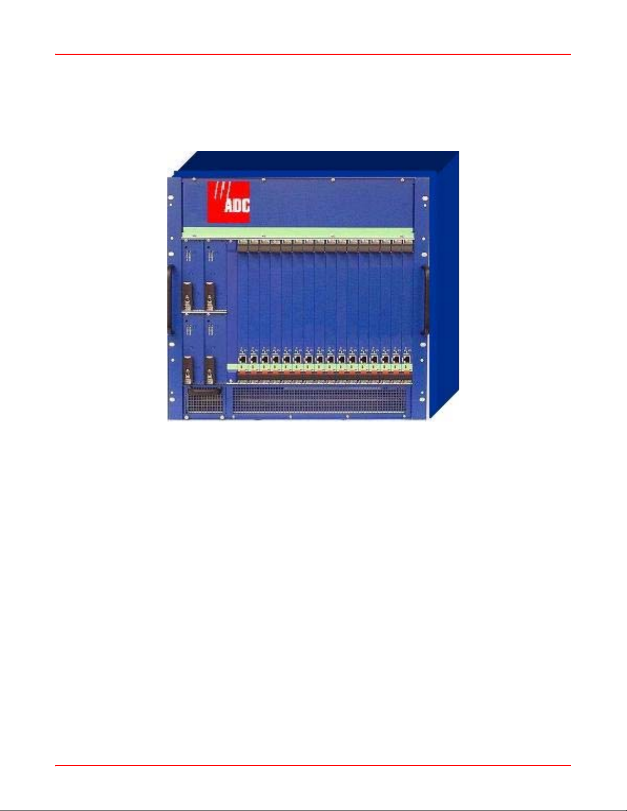
The SG-1 comprises two types of system chassis: 1U and 10U. The 1U chassis (or Mini System Chassis) has 2
service creation slots and 1 power supply slot built into the chassis. The 10U chassis (or Full-Size System Chassis)
has 16 service creations slots and 4 power supply slots for load sharing redundancy (see Figure 1-1).
Figure 1-1. SG-1 10U
BEFORE YOU BEGIN
Before installing the SG-1 chassis and its associated modules, it is important to prepare for installation by:
• Preparing the site (site preparations) and reviewing the instal la tion plans.
• Establish a Method of Procedure (MOP).
• Unpacking and inspecting the system components.
• Gathering the tools to properly install th e SG-1 chassis and its associated modules.
SITE PREPARATIONS
Typically, you should have prepared the installation site beforehand. As p art of your prep aration, obt ain a plan of the
site or Telco environment where the SG-1 chassis will be installed. All personnel involved in the installation of the
SG-1 chassis, including installers, engineers, and supervisors, should participate in the preparation of a MOP for
approval by the customer.
Method of Procedure
An example of a pre-installation checklist of tasks and considerations (Method of Procedure) that needs to be
addressed and agreed upon before proceeding with the installation is given below:
• Assign personnel.
• Determine protection requirements for personnel, equipment, and tools.
• Evaluate potential hazards that may affect service.
• Schedule time for installation.
• Determine any power and space requirements.
1-2 SG1-UM-8500-03
Page 15

June 30, 2006 Chapter 1: Overview
• Identify any required procedures and tests.
• On an equipment plan, make a preliminary decision that locates each of the SG-1 chassis tha t you plan
to install.
• Read this manual, whether you are replacing or adding a SG-1 chassis that is being installed.
• Verify the list of repl aceable parts for the installation (screws, bolts, washers, and so on) so that the parts are
identified (see Table 1-1 on page 1-4).
• Check the required tools list to make sure the necessary tools are available (see “Required Tools and Equip-
ment” on page 1-5).
• Purchase necessary parts.
• Identify work steps and any necessary notifications to CO personnel or engineers before work begin s.
• Perform the installation (see Chapter 2: Installation).
UNPACKING AND CHECKING THE CONTENTS OF YOUR SHIPMENT
The shipping package for the SG-1 chassis is designed to reduce the po ssibility of product dama ge associated with
routine material handling experienced during shipment. To reduce the potential damage to the product, transport the
chassis in its ADC-specified packaging. Failure to do so may result in damage to the chassis. Do not remove the
chassis from its shipping container until you are ready to install it.
Note: Do not discard the packaging materials used in shipping your SG-1 chassis. You will need the
packaging materials in the future if you move or ship your SG-1 chassis.
Table 1-1 on page 1-4 provides a list of required and optional components that may not be included in the SG-1
chassis kit, but are either required or recommended for the SG-1. A notes section (Table 1-2 on page 1-4) has been
provided to document any components not listed below .
SG1-UM-8500-03 1-3
Page 16
Chapter 1: Overview June 30, 2006
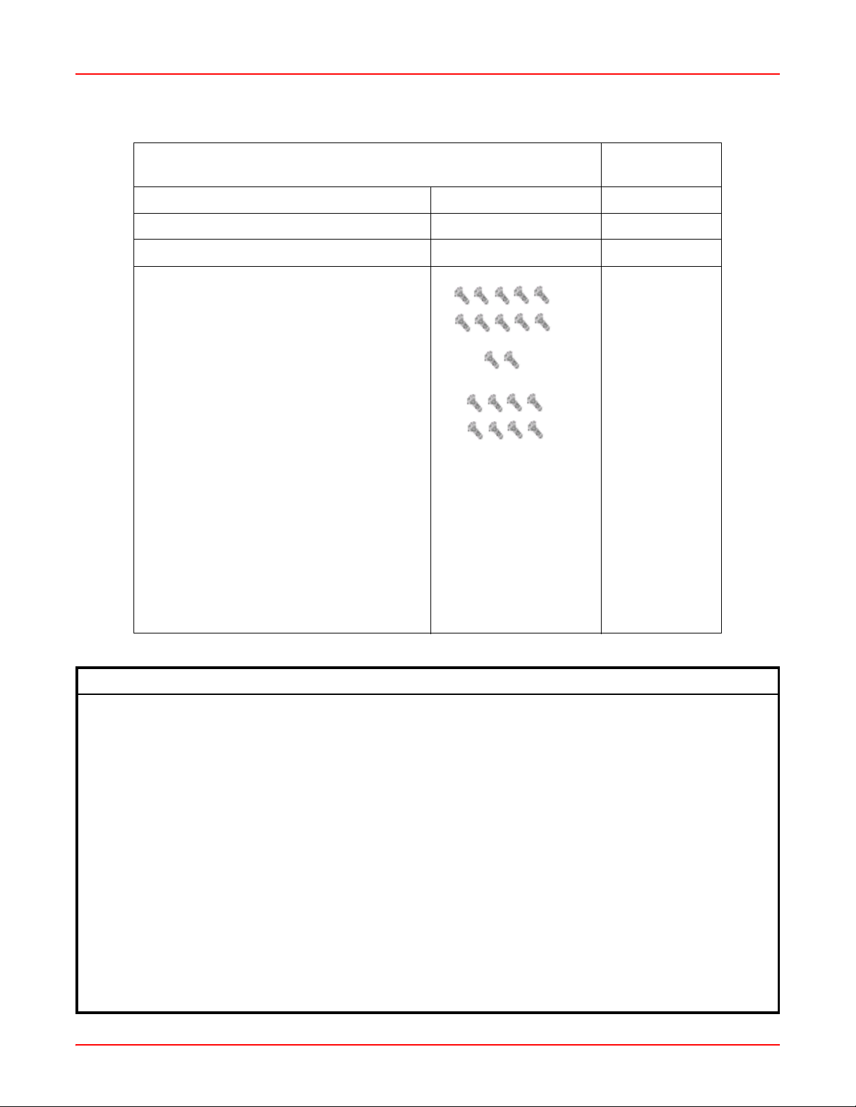
Table 1-1. Packing List
Catalog/Part
Item
SG-1 Service Gateway System Chassis
SG-1 Service Gateway System User Manual
SG-1 Service Gateway System Installation Kit
• Ten (10) 6-32 x 3/16 screws:
• Two (2) 8-32 x 5/16 screws:
• Eight (8) 12-24 x 3/8 screws:
Number
Notes:
• Two (2) mounting brackets
• One (1) #6 ground cable
• DB9/RJ45 “F” connector
Table 1-2. System Installation Notes
1-4 SG1-UM-8500-03
Page 17

June 30, 2006 Chapter 1: Overview
REQUIRED TOOLS AND EQUIPMENT
The following tools are required to install the SG-1 chassis:
• Grounding or ESD-preventive wrist strap
• No. 2 Phillips-head screwdriver
• Multimeter (for continuity testing)
• Wire stripper
• Wire-wrap tool
• Box cutter
• #26 AWG wire
SPECIFIC SG-1 CHASSIS INSTALLATI ON REQUIREMENTS
The SG-1 chassis dimensions are:
• Height of 17.50 inches (44.4 cm) (10U)
• Width of 19.0 inches (44.8 cm) without rack adapters attache d to the left and right side of the unit
• Depth of 11.4 inches (28.9 cm)
IMPORTANT
!
Location Requirements
To install the chassis in an equipment room or central office:
• Install in a 19-inch, 23-inch, 24-inch, or 600 mm rack using the customer provided rack adapter brackets.
• Allow a 1-inch minimum clearance between the chassis to provide for proper air flow for cooling.
Use the following card types in the SG-1 chassis:
• Fast Ethernet card in slots 1 through 16
• Gigabit Ethernet card in slots 1 through 16
• ATM card in slots 1 through 16
• Rear I/O card on the rear of the chassis in slots 1 through 16
When selecting system components, consider future expansion of your SG-1 with items in T able 1-3 as possible
options.
Observe the clearances specified below in “Location Requirements” to provide proper air flow
for chassis cooling.
SG1-UM-8500-03 1-5
Page 18

Chapter 1: Overview June 30, 2006
Table 1-3. Possible SG-1 Options
If you want to add: Then:
SG-1 chassis Consider installing the first chassis in the top
position of a rack to allow for further expansion
below it.
Fast Ethernet Port Add a Rear I/O card on the corresponding rear
slot of an SCC that Fast Ethernet access is
desired.
Service Creation Cards:
VRRP Use an SCC of the same type in any slot (1
through 16). Consider placing cards participating
in functional groups in adjacent slots for ease of
identification.
Redundancy Add an additional SCC, of the same type, in slots
1 through 16 to have an additional card that
provides the same service in the event of a card
or connectivity failure.
POWER REQUIREMENTS
The following specifies the power versions available for the SG1 chassis, then specifies the power requirements for
your facility relative to the SG1 power version you selected.
SG-1 Chassis
The SG-1 chassis provides four 100 to 240 Vac (50 to 60 Hz) power supplies with AC power co nnectors. You must
install one power supply for every five Service Creation Cards installed in a chassis (three power supplies are
required for a chassis having slots 1 through 16 fully populated). If you want redundant power, install an additional
power supply in an open power module slot. It is recommended to have one power module above the minimum to
provide uninterrupted service should a power module fail.
Facility Requirements for AC Power
Verify that the facility AC power sour ce for the primary connection falls with in the recommended voltage rang e of 1 10
to 220 Vac with a maximum current of 10 amps for 110 Vac and 5 amps for 220 Vac.
BLANK FACEPLATE REQUIREMENT
When slots in an SG-1 chassis do not contain a card, the slot must be covered with a blank faceplate to prevent
personnel contact with back panel connectors and to maintain proper air flow within the chassis.
ENVIRONMENTAL REQUIREMENTS
The SG-1 chassis has an ambient operating temperature range of +32 to +104° F (0 to +40° C) with a maximum
humidity of 95% when installed according to the instructions in this inst alla tion manual.
The storage temperature range is from -4 to +158° F (-20 to +70° C).
SYSTEM CABLING REQUIREMENTS
You will complete only the cabling appropriate for the cards installed in the chassis.
1-6 SG1-UM-8500-03
Page 19

June 30, 2006 Chapter 1: Overview
Chassis Ground and Power Cabling
The recommended cabling to ground the SG-1 cha ssis is 6 AWG (minimum) stranded copper wire.
For the SG-1 chassis, the recommended cabling is 14 AWG (1.88 mm diameter) stra nded copper or 14 A WG (1.628
mm diameter) solid wire to connect the DC terminal block to the facility provided power.
For the SG-1 chassis power cable, use one of the following:
• PC US for North America
• PC EURO for Europe
• PC UK for the United Kingdom
Network Cabling
Network connectors interface the SG-1 to an ATM backbone network, a LAN, or a WAN.
Configuration Port Cabling
In addition to the RJ-45 craft port provided on the front panel of each SCC card, each card may have a rear access
RS-232 interface through a RJ-45 connector for craft access and configuration if a Rear I/O card is installed. There
are two Ethernet ports located on the Rear I/O card.
Note: The Rear I/O card is optional when used with an ATM or Gigabit SCC.
SG1-UM-8500-03 1-7
Page 20

Chapter 1: Overview June 30, 2006
1-8 SG1-UM-8500-03
Page 21
Chapter
INSTALLATION
This chapter provides detailed information about installing the SG-1.
MOUNTING THE SG-1 CHASSIS
To mount the SG-1, complete the following procedure.
Step Action
1 If required, securely attach the customer provided rack adapters to the left and right sides of the rack in
which the SG-1 chassis will be installed.
2 Position the chassis in the rack.
3 Align the chassis adapter holes with the vertical rack mounting holes.
4 Secure the rack adapters to the rack using a Phillips screwdriver and four 12-24 x ½ inch pan head
screws for each rack adapter.
CONNECTING THE SG-1 CHASSIS GROUND
To connect the SG-1 chassis ground, complete the following procedure.
2
IMPORTANT
!
Step Action
1 Use the vendor provided cable.
2 Attach one end of the ground wire to the chassis ground lug and tighten the screw. Make sure the ground
3 Connect the other end of the ground wire to the CO ground termination point or building earth ground.
IMPORTANT
!
Attach your antistatic wris t st rap to the ESD ground jack on the SG-1 chassis.
The recommended copper wire is a minimum 6A WG stranded copper wire with a maximum length
of 5 feet (1.52 m).
wire has a secure connection.
Make sure the ground wire has a secure connection.
You must wear an antistatic wrist strap connected to the ESD jack on the SG-1 chassis to perform
the installation procedures. You must also observe normal ESD precautions when handling
electronic equipment. Do not hold electronic plugs by their edge. Do not touch components or
circuitry.
Note: Procedures marked with an ESD symbol require you to use the antistatic wrist strap to complete
the step.
CONNECTING THE POWER SOURCE
The SG-1 AC chassis (SG1-400-005) supports 110 to 240 Vac (50 to 60 Hz) power. Connect facility power to the
chassis as described in the following section.
SG1-UM-8500-03 2-1
Page 22
Chapter 2: Installation June 30, 2006
Connecting AC Power to an SG-1 AC Chassis
Connect an AC power cord(s) to AC power connectors, as required.
Step Action
1 Turn off the AC power switch on the back of the SG-1 AC chassis.
2 Plug the power cord into the chassis power connector.
3 Connect the AC power cord from the power supply to the facility power source. Do not turn on the power
switches at this time. You will turn on the power switches when you power up the chassis (as described in
“Powering Up the SG-1” on page 2-4) and install the cards (as described in “Installing Cards and Blank
Faceplates” on page 2-4).
INSTALLI NG INTERFACE CABLES
This section provides procedures for installing the cabling for the network, subscriber, and management interfaces.
Connecting Network Cards
Connect the SG-1 system, through a network card interface, to an ATM backbone network, WAN, or LAN for a
network uplink.
Refer to the following sections to complete cabling for the network interface connectors for these network cards:
• WAN ATM-OC3/STM1
• LAN GEthernet
Connecting the Ethernet Interface
The Rear I/O card provides two back panel access 10/100Base-T Ethernet interfaces.
Note: The Rear I/O is required for Fast Ethernet.
The Rear I/O card connector is MDI. Use one of the following cables as described below:
• Straight thro ugh cable to connect to a device with an MDI X port such as a hub, repeater, bridge, or router
• Cross over cable to connect to a device that also has an MDI port such as a PC with an Ethernet Network Interface Card (NIC)
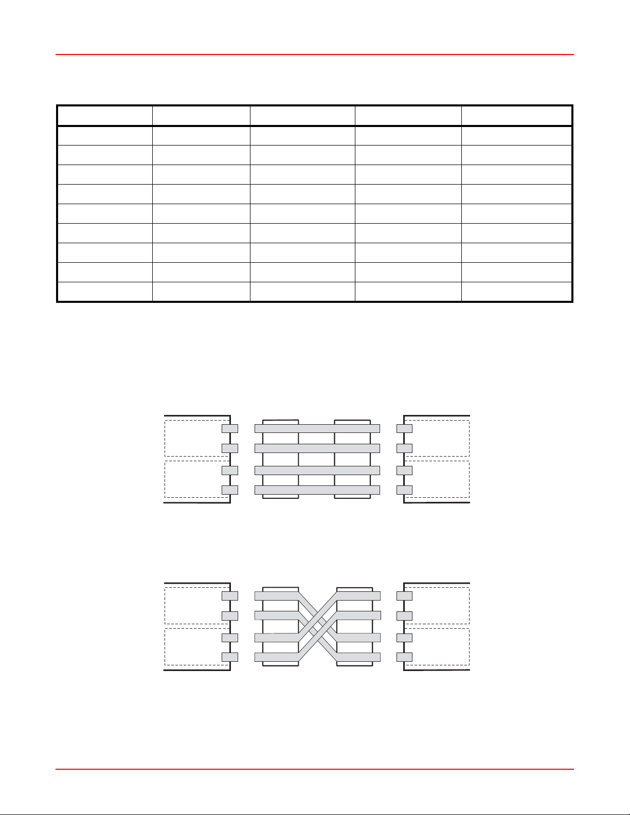
Table 2-1 shows the pin-outs for the RJ-45 connectors.
2-2 SG1-UM-8500-03
Page 23
June 30, 2006 Chapter 2: Installation
Table 2-1. RJ-45 Pin-Outs
MDI Pin Number MDI-X Pin Number Signal
a
Symbol Direction
1 3 Transmit Data (+) TX+ (TX0+) Out(Bidirect)
2 6 Transmit Data (-) TX-(TX0-) Out(Bidirect)
3 1 Receive Data (+) RX+(TX1+) In(Bidirect)
4 4 NC (TX2+) (Bidirect)
5 5 NC (TX2-) (Bidirect)
6 2 Receive Data (-) RX-(TX1-) In(Bidirect)
7 7 NC (TX3-) (Bidirect)
8 8 NC (TX3+) (Bidirect)
case case Chassis Ground
a.NC = no connection.
Figure 2-1 shows the pin-outs for straight-through and cross-connect cabling.
Straight-through cable
MDI-X port
(data network device)
3
6
1
Receive
2
Cable jack
3
6
1
2
Cable jack
3
6
1
2
MDI port
(management card)
3
6
1
2
Cross-over cable
MDI port
(data network device)
3
Receive Receive
6
1
Transmit Transmit
2
Cable jack
3
6
1
2
Cable jack
3
6
1
2
MDI port
(management card)
3
6
1
2
ReceiveTransmit
Transmit
Figure 2-1. Straight-Through and Cross-Over Cable Pin-Out s
SG1-UM-8500-03 2-3
Page 24
Chapter 2: Installation June 30, 2006
Connecting to an Ethernet Port
Step Action
1 Plug the RJ-45 connector of the Ethernet cable into the FAST E-NET port on the SG-1 chassis
back panel.
2 Connect the other end of the cable into the Ethernet port on the PC, hub, or other Ethernet device.
CONNECTING THE CRAFT PORT INTERFACE
In situations where a Rear I/O card is inst alled, the default cr af t port is on th e Rear I/O card. Moving a jumper on the
Rear I/O card is required if you wish to use the front craft port.
POWERING UP THE SG-1
IMPORTANT
!
Connect to facility power using an AC power cord and confirm proper function of th e AC power supplies.
Electrical and mechanical shock hazards are present throughout the system; be aware of this
possibility when power is applied to the chassis. Only qualified personnel should service the
system.
Step Action
1 Connect the power cord from the AC power connector on the SG-1 AC chassis back panel to the facility
power source. Turn on the power switch.
2 Verify that all cabling is securely terminated.
3 On each AC power supply, verify that the power LED lights green, indicating that the power supply is
receiving power.
INSTALLI NG CARDS AND BLANK FACEPLATES
Install SG-1 cards in the appropriate slots in the SG-1 chassis as indicated below. When slots do not have cards
installed, use blank faceplates as indicated below.
Installing Cards
Note: SG-1 cards are inserted under power (hot inserted).
CAUTION
Once you’ve powered up the chassis, as described in “Powering Up the SG-1,” you can begin to install cards in the
SG-1 chassis.
Refer to guidelines for “Site Preparations” on page1-2 to select the appropriate slot for a card, or refer to the
applicable card installation manual to select the appropriate slot and for detailed information on the card.
2-4 SG1-UM-8500-03
When inserting the cards, make sure the cards are properly aligned on the tracks to prevent
equipment damage or personal injury.
Page 25
June 30, 2006 Chapter 2: Installation
Installing Blank Faceplates
Use the blank faceplate identified in the “Blank Faceplate Requirement” on page 1-6.
IMPORTANT
!
Install blank faceplates in the SG-1 chassis to cover unused slots. Unused slots must be covered
to prevent personnel contact with back panel connectors under power and to maintain proper
airflow within the chassis.
Step Action
1 Slide the blank faceplate into the empty slot. Ensure the ret ainin g la tches are lifted.
2 Push the blank faceplate in until the retaining latches touch the SG-1 chassis.
3 Gently close the retaining latches until they snap into place .
4 Tighten the captive screw on the top and bottom retaining latches.
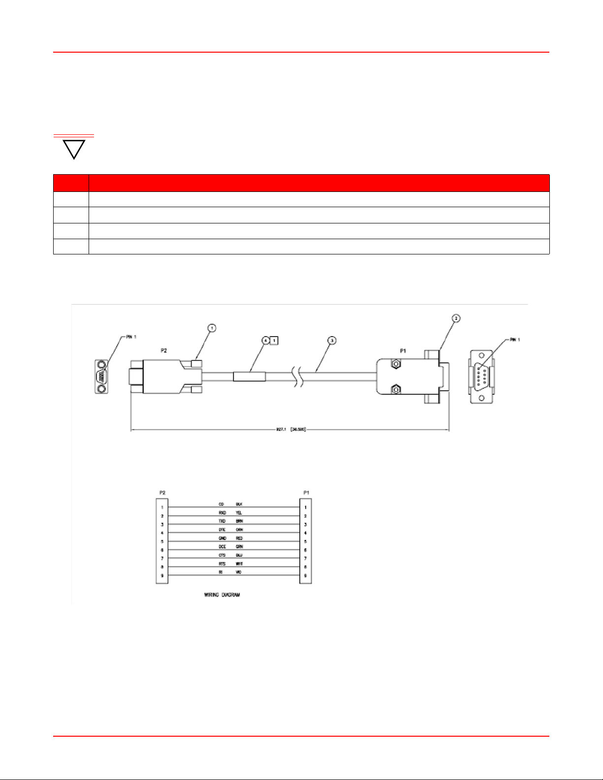
SERIAL CABLE
SG1-UM-8500-03 2-5
Page 26

Chapter 2: Installation June 30, 2006
2-6 SG1-UM-8500-03
Page 27

Chapter
3
COMMAND-LINE INTERFACE (CLI)
This chapter describes the SG-1 Command-Line Interface (CLI), the step s to a ccess the CLI, and the steps to
perform initial configuration using the CLI.
OVERVIEW
The SG-1 Service Gateway System management interface is accessed using a CLI, which provides comprehensive
SG-1 system management including configuration, performance monitoring, and system maintenance and
administration. An SG-1 Service Gateway System com prises an SG-1 10U Chassis with associated Service
Creation Cards (10/100 SCC, GiG-E SCC, ATM/GiG-E SCC) and rear I/O cards.
The command-line interface is accessed through the SCC (or rear I/O card if installed) COM port using either a
terminal connected directly to the COM port or over a network using a Telnet session. You can connect your Telne t
session from:
• A PC connected on the SG-1 Ethernet Local Area Network (LAN).
OR
• A remote PC connected over a router to the SG-1 Ethernet port.
This chapter provides an introduction to the command-line interfa ce structure and then pro vides information on how
to use it.
UNDERSTANDING THE INTERFACE STRUCTURE
The command-line interface has four system management m enus for administration, configuration, display, and
diagnostics.
These four system management menus comprise four sub-menus (Configuration, Main, Debug, and ConfigurationDebug). Table 3-1 provides a description of these sub-menus and their associated commands.
Table 3-1. SG-1 Sub-Menus and Associated Commands
Menu Types of Commands
Configuration Use the commands in this second level menu to configure:
• port configuration
• system passwords
• default authentication service type
• RADIUS parameters
• ACL permissions
• Tunnel server p ar ameters
• ATM parameters
• PPP and LCP configuration
• service parameters
• system parameters
• native IP parameters
• VRRP parameters
• IP parameters
• debug message levels
Main Use the commands in this menu to access other command levels and perform
system updates, system reloading, and network troubleshooting.
SG1-UM-8500-03 3-1
Page 28

Chapter 3: Command-Line Interface (CLI) June 30, 2006
Menu Types of Commands
Debug Use the commands in this first level menu to display system parameters
such as:
• Memory allocation
• Network/tunnel connections
• Sonet clock source
Configuration-Debug Use the commands in this third level menu to configure system debug
messages such as:
• Error and event level
• Time server IP address
• Log server IP address
COMMANDS AND NAVIGATION
Navigate the command-line interface by entering a command name or a command string to move to the appropriate
command level. The command level is indicated by the prompt. You can abbreviate command-line interface
commands if the abbreviations are distinct; however, you must use at least two letters of the command. Also, the
commands are not case sensitive. The following general and navigation commands are available from each prompt
(see Table 3-2 below and Table 3-3 on page 3-3, respectively).
Table 3-2. General Commands
Enter the following command: To:
? Display a list of commands available from the
current prompt.
command name? (for example, show?) Display an explanation of a particular command.
Exit Leave the current level and return to the
upper level.
Command Path Navigation
For each command that provides configuration or management of a SG-1 system, a path is provided in the
applicable section of the user document to help locate that command in the command-line interface structure. The
path will be displayed in a box before the description of the command.
3-2 SG1-UM-8500-03
Page 29

June 30, 2006 Chapter 3: Command-Line Interface (CLI)
COMMAND-LINE EDITING
The command-line interface provides a DOS-like environment for editing. It provid es special key functions and other
special functions developed for a VT100-type terminal.
Note: Commands may not be recognized under some vendor's versions of Telnet. With Microsoft®
Windows® HyperTerminal, or other terminal emulation programs, you may need to set the terminal
preferences to VT100 arrows to use these functions (see Table 3-3 on page 3-3).
T able 3-3 . Nav igation Commands
Use This Feature: To:
Up arrow key Provide the capability to scroll backward through
a list to retrieve information.
Down arrow key Provide the capability to scroll forward through a
list to retrieve information.
Tab key Allows the completion of a command given the
input of at least two characters and no other
ambiguous commands occur.
SG1-UM-8500-03 3-3
Page 30

Chapter 3: Command-Line Interface (CLI) June 30, 2006
3-4 SG1-UM-8500-03
Page 31

Chapter
4
ACCESSING THE COMMAND LINE INTERFACE
The initial step for managing the SG-1 Service Gateway System is to log on locally to an SCC or rear I/O port (if a
rear I/O card option is used) and set an IP address to allow for remote management via a Telnet session. This IP
address should place the SG-1 system on the same subnet as a router or other device to which it connects
upstream through its Ethernet port.
CONNECTING TO THE CRAFT PORT
Complete the following procedure to connect to the Craft port.
Step Action
1 Connect one end of a straight-thru Ethernet cable to the front of the SCC or the COM 1 port of a rear I/O,
if a rear I/O card is installed. Connect the other end of the straight-thru Ethernet cable to the DB9/RJ45
connector (provided in the SG-1 shipment) and then to the PC’s COM1 or COM2 port.
2 Power up the ASCII terminal or PC.
Please refer to the appropriate SCC installation manual for more detailed installation instructions, including the
location of the respective SCC Craft port and a description of the SCC Craft port connector pin-outs.
LOGGING ON TO THE CRAFT PORT
Complete the following procedure to log on to the Craft port.
Note: If the keyboard remains inactive for five minutes, the command-line interface Inactivity Timer
automatically logs the current user off. If this happens, log on to the command-line interface again. If
debugging is activated, you may have to press CTRL+C to access the login prompt.
Table 4-1. Default Username/Password
Username Password Authority
technician ggcon Full-access read/write
supervisor sg1 Read/write to second level
operator Popgate Read-only to first level with user
drop capability
viewer Popgate First-level show capabilities
If you are using a PC as a terminal, use a terminal emulation program such as HyperTerminal or Procomm™. Refer
to your terminal emulation program’s documentation for instructions.
Step Action
1 Configure the terminal or the PC terminal emulation program as follows:
• Baud rate: 19200 bps
• Data bits: 8
• Parity: none
• Stop bits: 1
• Flow control: none
2 When using a PC, select the COM setting of the port to which the RS-232 cable is connected (for
example, COM1 or COM2) using the terminal emulation program.
SG1-UM-8500-03 4-1
Page 32

Chapter 4: Accessing the Command Line Interface June 30, 2006
Step Action
3 Press ENTER to initiate the terminal session.
4 Enter your user name at the Username: prompt.
5 Enter your password at the Password: prompt.
The system will display the Host> prompt:
Welcome to SG-1 System
Username: technician
Password: *****
Login Successful
Host>
SETTING THE IP ADDRESS
Host> configure terminal
Host(config)# interface ethernet
Set the management card IP address, subnet mask, and default gateway (if a gateway exists) to enable
communication with external networks and to enable access to the SG-1 CLI for Telnet sessions.
To set a new IP address and subnet mask for the SCC, do the following.
Step Action
1 From the Host(config)# prompt, enter the interface command in the following format:
interface ethernet <slot number>\<port number> <ipaddr> <netmask> mode
<ethernet mode> [mtu <1500|1544>]
2 From the Host(config)# prompt, enter the ip default-gateway command in the following format:
ip default-gateway <ipaddr>
3 For this change to become permanent, the user must perform a write memory command from the
Host> first level prompt to save this change to NVRAM (when the save command is issued, it saves all
systems parameters):
write memory
4-2 SG1-UM-8500-03
Page 33

June 30, 2006 Chapter 4: Accessing the Command Line Interface
Parameter(s)
<slot number>\<port number>
The SCC and rear I/O interfaces have specific designations as shown in Table 4-2.
T a ble 4-2 . Interfac e Identificat ion
Card/Type Slot/Port 1 Slot/Port 2
Rear I/O 1/1 1/2
Gigabit Ethernet 1/1 1/2
ATM/GiG-E Card
ATM 2/1 2/2
GiG-E 1/1 1/2
<ipaddr>
The SCC IP address for interface in question. This address is set up to be on the same subnet as the Ethernet
network to which the SG-1 system is attached (format xxx.xxx.xxx.xxx).
<netmask>
The subnet mask associated with the SCC IP address. This address is based on the Ethernet network to which the
SG-1 system is attached (format xxx.xxx.xxx.xxx).
<mode>
T ab le 4-3. Et hernet Mode
Value Explanation
10H 10M half-duplex
10F 10M full-duplex
100H 100M half-duplex
100F 100M full-duplex
1000H 1000M half-duplex
1000F 1000M full-duplex
Auto Auto select mode
Example(s)
Host> configure terminal
Host(config)# interface ethernet 0 \ 2 12.3.66.211 255.255.255.0 auto mtu 1500
Added Item
SG1-UM-8500-03 4-3
Page 34

Chapter 4: Accessing the Command Line Interface June 30, 2006
DISPLAYING THE IP ADDRESS
Host> show configuration
From the Host> prompt, enter the show configuration command to verify your configuration.
Example(s)
Host> show configuration
…
interface ethernet 0\1 192.168.0.1 255.255.255.0 mode auto
ip default-gateway 192.168.0.253
…
When the show configuration command is entered, A screen similar to the one above displays the SG-1 SCC
card’s Ethernet port IP address, subnet mask, and default gateway (if applicable).
4-4 SG1-UM-8500-03
Page 35

Chapter
5
USING THE COMMAND LINE INTERFACE
There are multiple ways to access an SG-1 for management. Also, there are rules that determine the number of
accesses that can be made at one time to an SG-1 system. Once you have access, you can complete the
configuration and management of the SG-1.
CONFIGURING THE SG-1
The operational software for an SCC resides on each individual card. The software is accessed through a
command-line interface to configure and manage an SG-1.
The command-line interface can be accessed on an SG-1 locally through a serial interface to the Craft port on the
SCC (or rear I/O card) or through a Telnet session as shown below. The command-line interface modifies and views
the SG-1 Management Information Base (MIB) objects to implement system configuration and management.
Additionally, SG-1 can also be configured and managed through a customer-provided Element Management
System (EMS). The EMS uses SNMP to modify and view the SG-1 MIB objects.
LOGGING ON
In addition to logging on to an SG-1 locally through the Craft port, up to four additional remote users can log on
through a Telnet session.
The following example shows how to access the SG-1 CLI using a Telnet session from a remote system. S pecify the
IP address previously designated for this purpose:
C:\users\default>telnet 192.168.0.1
You receive a Welcome prompt when you successfully log on to the SG-1 CLI. Log on with the user account
information assigned to you.
Welcome to SG-1 System
Username: technician
Password: *****
Host>
LOGGING OFF
To log off, enter the exit command at the first level Host> prompt.
Host> exit
Note: The CLI Inactivity Timer automatically logs the current user off the system if the keyboard remains
inactive for five minutes.
SG1-UM-8500-03 5-1
Page 36

Chapter 5: Using the Command Line Interface June 30, 2006
WHAT TO DO NEXT
From the command-line interface, use the procedures in this manual to (among other things):
• Configure the network card ports, followed by services for the network connections, including Automatic Protection Switching (APS) for the OC3 card.
• Configure ATM traffic, including traffic profiles, policing, packet discard, over-subscription, and traffic shaping
for Unspecified Bit Rate (UBR) traffic.
• Set up ATM routing parameters for either IISP (static ATM routing) or Private Network to Node Interface
(PNNI) dynamic A TM routing.
• Set up system ATM configuration, such as signaling characteristics, ATM prefixes and addresses, ATM interfaces, and aliases for ATM addresses.
• Configure ATM connections for Permanent Virtual Circuits (PVC's).
• Set up bridging and routing global parameters and sessions over PVC's.
• Set up an IP/Ethernet uplink (bridging and rou ting over ATM PVC's) using an SCC card.
Use Table 3-1 on page 3-1 to navigate command menus and perform the necessary actions.
5-2 SG1-UM-8500-03
Page 37

Chapter
6
FIRST-LEVEL COMMANDS
This chapter describes the commands available at the first command level of each SCC.
You can enter the entire command or the first two letters of most commands and command-line arguments. If there
are two commands with the same first two letters, enter enough letters to differentiate between the two commands.
The remaining letters can be displayed, if you wish to see the complete command, by pressing TAB after the first
two letters. If a command-line argument is missing, the system responds by displaying the words Incomplete
command or illegal command directly below the position of the missing argument.
Previously used command lines can be retrieved by pressing the Up
these command lines. Any of the command lines can be executed by pressing ENTER when it appears on the
screen.
Y ou can view th e command options and command-line argument optio ns by typing ? at any point before a command
line is complete. For example, typing ? right after the prompt will provide a list of available commands, and typing ?
after a command will display a list of options for the next command-line argument. Similarly, typing ? after an option
will display a list of options for the following command-line argument.
The help facility can be used to obtain a list of the first-level commands and their functions by typing ? immediately
after the first-level prompt. The question mark does not appear on the screen, but the system responds by
displaying the information requested.
To verify the functionality of the initial configuration of the SCC, the commands at the first level may be used to:
1. Show hardware, software, and license versions
2. Show running configuration and port stat us
3. Show system information
4. Write to and Load from the system configuration on a TFTP server
5. Access the configuration menu
6. Disconnect users
7. Confirm network connectivity
8. View debug parameters
Ç and DownÈ arrow keys to browse the list of
SG1-UM-8500-03 6-1
Page 38

Chapter 6: First-Level Commands June 30, 2006
SHOWING A LIST OF AVAILABLE PARAMETERS
Using the GREP command
The GREP command may be operated on any of the system commands.
Usage
system-command | grep "string"
Example(s)
Host> show users | grep "moshe" <cr>
1 ANet PPP moshe 192.168.2.12 00:04:23 9568432
Host>
Host> write terminal |grep "interface" <cr>
interface loopback 1 10.1.208.1 255.255.255.0
interface ethernet 0\2 1.1.1.1 255.255.255.0 auto
Host>
Using the ? command
Host> ?
The list of available parameters can be viewed by typing ? at the first-level prompt.
6-2 SG1-UM-8500-03
Page 39

June 30, 2006 Chapter 6: First-Level Commands
Example(s)
Host> ?
show - Display running configuration and status
write - Write running configuration
copy-TFTP - copy-TFTP file from server
ping - Ping command
reload - Reload the system
clear - Disconnect line
traceroute - Traceroute command
exit - Exit SG-1 management session
configure - Modify running configuration
debug - Show debug information
Host>
Using the show ? command
Host> show ?
From the first-level
Example(s)
Host> show ?
show - Display running configuration and status
write - Write running configuration
copy-TFTP - copy-TFTP file from server
ping - Ping command
reload - Reload the system
clear - Disconnect line
traceroute - Traceroute command
exit - Exit PopMaestro management session
configure - Modify running configuration
debug - Show debug information
Host>
Host> prompt, enter show ? to view a list of available commands.
SG1-UM-8500-03 6-3
Page 40

Chapter 6: First-Level Commands June 30, 2006
These commands are discussed below.
Using the show version command
Host> show version
Enter show version to see version levels of hardware and software.
Usage
show version <software|hardware|pack>
show version software <SCC>
show version hardware <2>
Parameter(s)
<software|hardware|pack>
The first-level parameter has three options:
• software–Displays the software version of the SCC in question.
• hardware–Displays hardware information of the SCC in question.
• pack–Displays det ailed information of the installed software version.
<SCC>
The software version for the Service Creation Card in question.
<2>
Module number.
6-4 SG1-UM-8500-03
Page 41

June 30, 2006 Chapter 6: First-Level Commands
Example(s)
Host> show version software
Module Num Application
______ ___ ___________
SCC-ATM155 1 10.0T2.05 Jun 08 2006 17:18:19
Host>
Host> show version hardware
Module Num Part No. Serial No. Slot
_________ ___ _____________________ __________ ____
Backplane 1 710-200-0 Rev 0 0
SCC-ATM155 2 650-038 Rev 1 2079600287 1
Host>
Host> show version hardware 2
Service Creation Card with 256MByte memory module
Module Num Part No. Serial No. Slot
_________ ___ _____________________ __________ ____
SCC 1 650003 8200935 0
Host>
SG1-UM-8500-03 6-5
Page 42

Chapter 6: First-Level Commands June 30, 2006
Displaying the configuration in NVRAM
Host> show configuration
Usage
show configuration
6-6 SG1-UM-8500-03
Page 43

June 30, 2006 Chapter 6: First-Level Commands
Example(s)
Host> show configuration
# version: 10.0T2.05 Jun 08 2006 17:25:51
interface ethernet 0\1 172.16.1.13 255.255.255.128 auto
interface ethernet 0\2 172.16.13.193 255.255.255.128 auto
password viewer Tw)wtx password operator Tw)wtx password superuser +5z!#r-MGA
password technician Koz!#
password pre-authentication +k(~#i+^#43\,6
def-service-auth ppp-auto
multilink-mode multi-cage
radius-server host 172.16.1.15 auth-port 1812 acct-port 1813 m priority 3
radius-server key netix
access-list SNMP-permit 0.0.0.0 0.0.0.0
access-list SNMP-permit 10.0.0.0 255.0.0.0
access-list SNMP-permit 172.16.0.0 255.255.0.0
access-list SNMP-permit 192.168.1.1 255.255.0.0
access-list EDS-permit 10.0.1.203 255.255.255.255
access-list EDS-permit 162.10.1.0 255.255.255.0
access-list EDS-permit 172.16.1.2 255.255.255.255
access-list EDS-permit 172.16.1.15 255.255.255.255
access-list native-ip 172.16.13.0 255.255.255.0
SNMP-server community get T}y||g
SNMP-server community set T}y||g
tunnel-server host 0.0.0.0 mask 0.0.0.0
pppoe enable interface 0\1 0
router id 172.16.1.13
hostname Mankali
banner BannerString
session-timeout 500000
idle-timeout 1800
lcp renegotiate
service cache off
service internal framed-PPP
native-ip dhcp pre-auth-mode mac
native-ip def-service-auth Guest
native-ip enable interface Ethernet 0\2
SG1-UM-8500-03 6-7
Page 44

Chapter 6: First-Level Commands June 30, 2006
ip local-pool pool1 162.10.1.1 162.10.1.254 internal
ip domain-name POPmaestro
ip primary-name-server 62.90.133.233
ip secondary-name-server 0.0.0.0
ip default-gateway 172.16.1.1
ip tcp adjust-mss on
ip dhcp relay server Ethernet 0\2 1 172.16.1.15
debug
watchdog-TimeValue 60
time-server-ip 0.0.0.0
error-level default 3 output-device console
event-level default 5 output-device console
trace default off
sysLog-server-ip 192.168.1.1
Host>
Note: Using show configuration for the first time on a blank system may return a File does not exist
message until the configuration is written to NVRAM using the write memory command.
6-8 SG1-UM-8500-03
Page 45

June 30, 2006 Chapter 6: First-Level Commands
Displaying Ethernet port configurations
Host> show terminal
Displaying Ethernet Port Statistics
Host> show ethernet 0 \ 1
Use the show ethernet command to display the Ethernet port parameters for the Rear I/O Ethernet port.
Note: When keying in the command, the backward slash ‘\’ is optional. The command will work with just a
space between the slot number and port number.
Usage
show ethernet <slot number> <port number>
Parameter(s)
<slot number>
The slot number refers to 0 (for the Rear I/O) card and 1 for a Gigabit Ethernet port on the SCC card itself.
<port number>
The port number refers to a value of 1 to 3 for the card in question.
SG1-UM-8500-03 6-9
Page 46

Chapter 6: First-Level Commands June 30, 2006
Example(s)
Host> show ethernet 0 \ 1
Interface Slot 0 Port 1 is up, line protocol is up
Hardware address is 008042195FB7
Internet address is 10.0.1.220 Mask is 255.255.255.0
Gateway IP address is 10.0.1.253
Duplex mode sensed by auto-negotiation is full-duplex
Ethernet speed is 1 Gbps
MTU 1500 bytes, BW 1000 Mbps
23778 packets input, 1997552 bytes
Received 5473 broadcast
, 0 runts, 0 giants, 0 CRC
Input frame discard = 0
Assign Rx buffers failure = 0
Free Rx buffers = 1005
13879 packets output, 1386325 bytes
0 output errors, 0 output late collisions, 0 retry
0 re-transmission limit
Output discards = 0
Redundancy status: redundancy is not configured
Host>
6-10 SG1-UM-8500-03
Page 47

June 30, 2006 Chapter 6: First-Level Commands
Displaying SONET port status
Host> show port sonet
Usage
show port sonet
Parameter(s)
None.
Example(s)
Host> show port sonet
ATM_SCC> show port sonet
Slot Port Status Capacity Redundant Redundant
Conf Status
____ ______ ________ ___ ___________ ______
2 1 OK 155 working active
2 2 OK 155 protected not-active
ATM_SCC>
SG1-UM-8500-03 6-11
Page 48

Chapter 6: First-Level Commands June 30, 2006
Displaying ATM Port Status
Host> show atm pvc
Usage
show atm pvc
Parameter(s)
None.
Example(s)
Host> show atm pvc
Name VPI VCI Slot Port Sub-port PCR Status
______ ____ ____ ____ ______ ________ ___ ______
none 0 32 2 1 1 155 UP
test 2 32 2 1 1 155 UP
test 2 33 2 1 1 155 UP
test 2 34 2 1 1 155 UP
test 2 35 2 1 1 155 UP
next 2 36 2 1 1 155 UP
next 2 37 2 1 1 155 UP
next 2 38 2 1 1 155 UP
Host>
6-12 SG1-UM-8500-03
Page 49

June 30, 2006 Chapter 6: First-Level Commands
Displaying User Status
Host> show user
Usage
show [<cr>|<number>]
Parameter(s)
[<number>]
The line number of the user to be viewed.
Example(s)
Host> show users
Line Line User User Name IP Address Duration Calling
Type Type hh:mm:ss Number
____ ____ ____ __________ __________ ________ _______
52 Eth PPP status 155.226.20.50 00:01:00 0010A4C15AFB
Total number of Network connected lines: 1
ANet (Analog source) lines: 0, INet (ISDN source) lines: 0
Eth (Ethernet source) lines: 1
ATM (ATM source) lines: 0
EATM (ATM source) lines: 0
PPP (PPP source) lines: 1
Total number of Framed users: 1
PPP users: 1, MLP users: 0
Total number of tunnel switch users: 0
Total number of native IP users: 0
NIPP (radius-proxy triggered) users: 0
NIPD (dhcp-proxy triggered) users: 0
NIPI (ip triggered) users: 0
Host>
SG1-UM-8500-03 6-13
Page 50

Chapter 6: First-Level Commands June 30, 2006
Host> show users 704
Line number: 702 Line type: ANet User type: PPP
User name: 0_220
IP address: 10.220.3.191, IP pool name: 1
Next Hop: 10.0.1.253
Tunnel ID(in): 4798 Tunnel Session ID(in): 21182 LAC source IP 10.0.1.64
Session duration/timeout: 00:00:39 / 17:59:21
Idle duration/timeout: 00:00:35 / 00:30:00
Slot: 0 Port: 1
Calling number: <N/A> Called number: 0
Input packets/Octets: 3 / 30,
Output packets/Octets: 3 / 42,
Used Data Quota: 0
PPP Native IP Pipe: Off
Redirect Gateway: <N/A> Accounting Type: Standard
User Group: 0 DHCP Server IP: <N/A>
Service name: Original-Service
Service duration: 00:00:40
Host>
6-14 SG1-UM-8500-03
Page 51

June 30, 2006 Chapter 6: First-Level Commands
Displaying Routing Tables
Host> show ip-route
Use this command to display the configured routes.
Usage
show ip-route
Parameter(s)
None.
Example(s)
Host> show ip-route
Network NetMask Gateway Interface
Address Address
___________ _____________ ___________ __________________
155.226.21.0 255.255.255.0 0.0.0.0 Ethernet [ 0\2 ]
155.226.22.128 255.255.255.128 0.0.0.0 Ethernet [ 0\2 ]
Host>
Displaying System Administrators
Host> show telnet-users
Usage
Use this command to display the system administrators that are logged onto the system.
Parameter(s)
None.
Example(s)
Host> show telnet-users
Number User Level Duration Source
______ __________ ________ ______
1 Technician 00:01:07 Console
2 Technician 00:00:08 Network
Host>
SG1-UM-8500-03 6-15
Page 52

Chapter 6: First-Level Commands June 30, 2006
Displaying System Parameters
Host> show system
Usage
show system
show system <load>
Parameter(s)
<load>
Calculates the throughput through each interface in Mbps.
Example(s)
Host> show system
Up-time: 1 Hours, 56 Minutes, 58 Seconds
Total number of network incoming calls: 702
Total number of network connected calls: 702
Current number of Network connected lines: 1
ANet (Analog source) lines: 1, INet (ISDN source) lines: 0
Eth (Ethernet source) lines: 0
ATM (ATM source) lines: 0
Ethernet Over ATM (EATM source) lines: 0
Current number of PPP (PPP source) lines: 0
Current number of connected Framed users: 1
PPP users: 1, MLP users: 0
Current number of connected native IP users: 0
Host>
6-16 SG1-UM-8500-03
Page 53

June 30, 2006 Chapter 6: First-Level Commands
Host> show system load
Calculating load ...
Total current connected users: 0
Total sessions' capacity: 2000
System load: 0%
CPU usage: 1%
Interface 0/2
Throughput [5 sec. Avg.]: 0.0 Mbit/s In, 0.0 Mbit/sec Out
Total available throughput: 100 Mbit/s In, 100 Mbit/sec Out
Traffic Usage: In 0.0%, Out 0.0%
Interface 1/1
Throughput [6 sec. Avg.]: 0.0 Mbit/s In, 0.0 Mbit/sec Out
Total available throughput: 1000 Mbit/s In, 1000 Mbit/sec Out
Traffic Usage: In 0.0%, Out 0.0%
Interface 2/1
Throughput [6 sec. Avg.]: 0.0 Mbit/s In, 0.0 Mbit/sec Out
Total available throughput: 155 Mbit/s In, 155 Mbit/sec Out
Traffic Usage: In 0.0%, Out 0.0%
Host>
SG1-UM-8500-03 6-17
Page 54

Chapter 6: First-Level Commands June 30, 2006
Displaying License Attributes
Host> show license
This command displays the system license information.
Usage
show license
Parameter(s)
None.
6-18 SG1-UM-8500-03
Page 55

June 30, 2006 Chapter 6: First-Level Commands
Example(s)
Host> show license
Working license : permanent
Temp License Magic: T001001086
[CREATION]
DATE=December 22 2005 16:03:57
[VERSION]
MAJOR=10
[SN]
SNSOURCE=1
SNNUM=1
SN1=6046838
[MAGIC]
Magic String=C000000067
MaxAllowedDays=30
[OPTIONS]
Allow Maximum 500 Users=off
Allow Maximum 1000 Users=off
Allow Maximum 2000 Users=on
Allow Maximum 4000 Users=off
Gigabit Ethernet=on
ATM=on
Pre Paid=on
Bandwidth Control=on
Hierarchical Bandwidth Control=on
Customized Guided Entry=on
Dynamic COS=on
Differentiated Routing=on
SG1-UM-8500-03 6-19
Page 56

Chapter 6: First-Level Commands June 30, 2006
Filter Redirection=on
Location Based Service=on
Service Selection=on
Native IP=on
Dynamic IP Changing=on
Application Awareness=on
MPLS=on
Native IP Roaming=on
Host>
6-20 SG1-UM-8500-03
Page 57

June 30, 2006 Chapter 6: First-Level Commands
Displaying VRRP attributes
Host> show vrrp interface
Use this command to display the configured Virtual Router Redundancy Protocol (VRRP) status on the specified
interfaces.
Usage
show vrrp interface (<ethernet>|<vlan>) <slot number> <port number> <number>
Parameter(s)
(<ethernet>|<vlan>)
The interface will be either an Ethernet or VLAN interface.
<slot number>
Slot number; valid values are 0 to 3.
<port number>
Defines the port; valid values are 1 or 2.
<number>
Defines the Virtual Router ID number (VRID); valid values are 1 to 15.
Example(s)
For the master:
Host> show vrrp interface Ethernet 0\1
Ethernet 0\1 - Group 1
State is Master
Virtual IP address is 192.168.1.1
Master router is 192.168.1.2 (local)
Virtual MAC address is 00-00-5E-00-01-01
Advertisement interval is 1 seconds
Priority 254
Preemption mode: off
Host>
SG1-UM-8500-03 6-21
Page 58

Chapter 6: First-Level Commands June 30, 2006
For the backup:
Host> show vrrp interface Ethernet 0\1
Ethernet 0\1 - Group 1
State is Backup
Virtual IP address is 192.168.1.1
Master router is 192.168.1.2
Virtual MAC address is 00-00-5E-00-01-01
Advertisement interval is 1 seconds
Priority 100
Preemption mode: on
Host>
Displaying active GRE and IP-in-IP tunnels
Host> show ip-tunnel
This command displays the active GRE and IP-in-IP tunnels in the system.
Usage
show ip-tunnel [gre | ip-in-ip [<remote endpoint Ip address> <tunnel direction>]]
Parameter(s)
None.
6-22 SG1-UM-8500-03
Page 59

June 30, 2006 Chapter 6: First-Level Commands
Example(s)
Host> show ip-tunnel <cr>
Tunnel IP Tunnel Total Tunnel Tunnel
Endpoint Sessions Status Type
--------------- ---------- -------- ------- ------
192.168.1.1 remote 20 unknown gre
10.10.2.234 remote 11 up ip-in-ip
10.10.1.20 remote 7 down ip-in-ip
Host>
Host> show ip-tunnel ip-in-ip <cr>
Tunnel IP Tunnel Total Tunnel Tunnel
Endpoint Sessions Status Type
--------------- ---------- -------- ------- ------
10.10.2.234 remote 11 unknown ip-in-ip
10.10.1.20 remote 7 up ip-in-ip
Host>
Host> show ip-tunnel ip-in-ip 10.10.1.20 remote <cr>
Line Line User User-name IP address
Type Type
---- ---- ---- --------------- -------------- 2 Eth NIPI test1 212.168.1.4
5 Eth NIPI test2 212.168.1.5
56 Eth NIPI test3 212.168.1.6
Host>
SG1-UM-8500-03 6-23
Page 60

Chapter 6: First-Level Commands June 30, 2006
Displaying show mpls-labels commands
Host> show mpls-labels
It displays the incoming labels binding received from the neighbors and the out-going label binding distributed by the
system. When no specific FEC is defined, the system shows all FECs.
Usage
Show mpls-labels <standard | vc> <out | in> [<FEC identifier>]
Parameter(s)
<standard | vc>
Standa rd labels are the first labels on the sta ck, while vc labels (tunne ls) ar e the second lable on the stack.
<out | in>
Lables that are out-going or incoming.
<FEC identifier>
It is the FEC (Forward Equivalence Class) identifier .
Note: The system default value is 0 (which means all FECs).
Example(s)
Standa rd in:
Host> show labels standard in
FEC ID IP destination FEC Label Next-Hop Interface
1 192.168.1.0/24 123876 10.0.1.8 Ethernet 1
2 212.8.1.0/24 1034 10.0.1.3 Ethernet 1
Standa rd out:
Host> show labels standard out
FEC ID IP destination FEC Label
1 192.168.1.0/24 123876
2 212.8.1.0/24 1034
6-24 SG1-UM-8500-03
Page 61

June 30, 2006 Chapter 6: First-Level Commands
VC in for Martini draft:
Host> show labels vc in
VC ID VC Type Group ID Label Tunnel Endpoint Upper stack FEC ID
1 LAN 0xc2010000 123876 192.0.1.8 1
2 LAN 0xc2010000 123876 192.0.1.8 1
1 VLAN 0xc2010001 1034 212.1.3.4 2
1 PPP 0xc2010002 1035 195.3.4.5 3
VC OUT for Martini draft:
Host> show labels vc OUT
VC ID VC Type Group ID Label Tunnel Endpoint
1 LAN 0xc2010000 123876 192.0.1.8
2 LAN 0xc2010000 123876 192.0.1.8
Standard in specific FEC lable:
Host> show labels in 192.168.1.0/24 <cr>
FEC Label Next-Hop Interface
192.168.1.0/24 123876 10.0.1.8 Ethernet 1
SG1-UM-8500-03 6-25
Page 62

Chapter 6: First-Level Commands June 30, 2006
Displaying show mpls l2transport vc commands
Host> show mpls l2transport vc
It shows confine redirected interface traffic through MPLS l2vpn tunnel based on Martini draft.
Example(s)
Host> show mpls l2transport vc
Dest address VC ID Status Type
194.90.1.4 200 UP redirect
194.90.1.4 201 UP redirect
Displaying a list of available write commands
Host> write ?
This command shows the available write commands enabled on the SCC.
Usage
write [<memory>] | [<network><ip address><alpha numeric string>] | [<terminal>]
Parameter(s)
<memory>
Writes running configuration (volatile memory) to start-up configuratio n (non-vo la tile).
<network>
Writes running configuration to a TFTP server.
<ip address>
IP address of TFTP server.
<alpha numeric string>
Name to be used for configuration saved to a TFTP server.
<terminal>
Writes running configuration to terminal screen.
6-26 SG1-UM-8500-03
Page 63

June 30, 2006 Chapter 6: First-Level Commands
Example(s)
Host> write terminal
# version: 10 May 21 2006 15:14:31
password viewer Tw)wtx password operator Tw)wtx password superuser +5z!#r-MGA
password technician Koz!#
password pre-authentication +k(~#i+^#43\,6
def-service-auth ppp-auto
multilink-mode multi-cage
radius-server key netix
SNMP-server community get T}y||g
SNMP-server community set T}y||g
banner BannerString
session-timeout 64800
idle-timeout 1800
service cache on aging-time 10
service internal framed-PPP
ip domain-name SG1
ip tcp adjust-mss off
debug
watchdog-TimeValue 600
time-server-ip 0.0.0.0
trace off
sysLog-server-ip 0.0.0.0
Host>
Host> write network 155.226.20.250 test
Preparing configuration file.................................
Done.
Starting the TFTP upload.......
Done.
Host> write terminal
SG1-UM-8500-03 6-27
Page 64

Chapter 6: First-Level Commands June 30, 2006
Using the copy-TFTP command
Host> copy-TFTP flash
Use this command to copy a new application software (image) or license file from a TFTP server to the flash
memory of the SCC-ETH card.
Usage
copy-TFTP flash [<IP address> | <license>] <ip address> <file name>
Note: The SG-1 as a service creation machine uses a license mech anism, which enables the activation and
deactivation of specific services. Use the [license] parameter to upgrade the current version of the
license file running on the SCC.
Parameter(s)
<ip address>
This is the IP address of the TFTP server to be used for the software or license upgrade.
<license>
This parameter will allow the upgrading of a license file on the SCC.
<file name>
This is the file name used for the software or license upgrade (the file name is 1 to 64 alphanumeric characters).
Example(s)
Host> copy-TFTP flash 192.168.0.1 V10_PM
Download in progress
99%
Closing the download process.
Pack loaded successfully.
In order to use new software, please reload the system
Host>
Host> copy-TFTP flash license 192.168.1.2 lic101.txt
Using the ping command to test network connectivity
Use the Ping command to elicit an ICMP ECHO_RESPONSE from a host or gateway. This command can be used
to send a PING via an ATM or IP interface.
Usage
ping <ip address> [-c <number>| -i <number> | -s <number>] [atm <atm slot number>
<atm sub-interface number> <atm vpi number> <atm vci number> (end-loopback|repeat
<number>)]
Parameter(s)
<ip address>
6-28 SG1-UM-8500-03
Page 65

June 30, 2006 Chapter 6: First-Level Commands
The destination ip address to ping.
[-c <number>]
The number of echoes.
[-i <number>]
The number of wait seconds.
[-s <number>]
The number of bytes.
[atm]
The ATM interface.
[atm <slot number>]
The ATM slot number (ATM uses slot 2).
[atm <atm port number>]
The ATM port number (either port 1 or port 2).
[atm <sub-interface number>]
The ATM sub-interface number.
[atm <vpi number>]
The ATM vpi number.
[atm <vci number>]
The ATM vci number.
[atm (end-loopback)]
Verifies end-to-end PVC integrity.
[atm (repeat <number of echoes>]
The number of echoes to be sent.
Example(s)
Host> ping -c 5 -i 5 -s 500 155.226.20.250
Press <Ctrl C> to abort.
508 bytes from 155.226.20.250:icmp_seq=1 ttl=63 time<20 ms
508 bytes from 155.226.20.250:icmp_seq=2 ttl=63 time<10 ms
508 bytes from 155.226.20.250:icmp_seq=3 ttl=63 time<10 ms
508 bytes from 155.226.20.250:icmp_seq=4 ttl=63 time<10 ms
508 bytes from 155.226.20.250:icmp_seq=5 ttl=63 time<20 ms
Host>
SG1-UM-8500-03 6-29
Page 66

Chapter 6: First-Level Commands June 30, 2006
Using the reload command to restart the system
Host> reload non-graceful
Use the reload non-graceful command to reset the system and reload the software. Using this command will
terminate all sessions.
Usage
reload non-graceful
Parameter(s)
None.
Example(s)
Host> reload non-graceful
Resetting the system in 10 seconds...
6-30 SG1-UM-8500-03
Page 67

June 30, 2006 Chapter 6: First-Level Commands
Clearing Users
Host> clear user
A specific user can be disconnected from the SG-1 by writing the clear user command followed by its line number.
Usage
clear user <line number>
Note: You can use the show user command to determine the list of connected users.
Note: If the user is a multi-link user , the following message will appear: Note that multi-link users
may have other lines that are still connected.
Parameter(s)
<line number>
The line number of the user to be cleared.
Example(s)
Host> clear user 22
Note that multi-link users may have other lines that are still connected
SG1-UM-8500-03 6-31
Page 68

Chapter 6: First-Level Commands June 30, 2006
Using the Tr aceroute Command
Host> traceroute
Use the traceroute command to track the route a packet takes to a network host.
Usage
traceroute <ip address> [-h <number>| -i <seconds>]
Parameter(s)
<ip address>
The IP address to which the trace is to be performed.
[ -h <number>]
The maximum number of hops to be attempted (max = 30).
[ -i <seconds>]
The max. number of seconds to wait for a response.
Example(s)
Host> traceroute 155.226.10.200
Press <Ctrl C> to abort.
1 < 20 ms < 10 ms < 10 ms 155.226.20.240
2 < 10 ms < 10 ms < 10 ms 155.226.248.14
3 < 10 ms < 10 ms < 10 ms 155.226.1.2
4 < 10 ms < 10 ms < 10 ms 155.226.10.200
Traceroute completed successfully
Host>
6-32 SG1-UM-8500-03
Page 69

June 30, 2006 Chapter 6: First-Level Commands
Using the exit command
Host> exit
This command exits the user from the current configuration level. When used at the fir st level, the user is logged out
of the session.
Usage
exit
Parameter(s)
None.
Example(s)
Host> (config-debug)# exit
Host> (config)#
Host> (config)# exit
Host> exit
SG1-UM-8500-03 6-33
Page 70

Chapter 6: First-Level Commands June 30, 2006
USING DEBUG MODE
This section provides information on the commands and options available in debug mode.
Switching to Debug Mode
Host> debug
Use the debug command at the first-level prompt (Host>) to switch the system to the second-level debug prompt:
Host(debug)#. This prompt indicates that the user is now in the second-level debug mode and has access to the
five second-level commands in the debug menu.
Usage
Step Action
1Use the show command to display memory, system and fragmentation information.
2The port sonet source-clock command determines timing configuration for the ATM port specified.
3 At this level, the exit and end commands will return the user to the first configuration level.
4 From the Host> prompt, enter the debug comma n d in the follo win g fo rm at :
debug
Parameter(s)
None.
Example(s)
Host(debug)# ?
show - Display debug parameters
port - Select a port to configure
port-ethernet - Port ethernet interface
radius-server - radius server command
clear - Clear arp table
exit - Exit current level
end - Return to first level
Host(debug)#
6-34 SG1-UM-8500-03
Page 71

June 30, 2006 Chapter 6: First-Level Commands
Using the show command in debug mode
Host(debug)# show
Use the show command to display memory, system, and fragmentation information.
Usage
show [memory | system |log-modules | statistics | arp]
Parameter(s)
[memory]
Display memory allocation.
[system]
Display connection information.
[log-modules]
Display system log modules.
[statistics]
Display fragmentation information.
[arp]
Display ARP information table.
SG1-UM-8500-03 6-35
Page 72

Chapter 6: First-Level Commands June 30, 2006
Example(s)
Host(debug)# show statistics fragmentation
Total number of packets that were fragmented: 0
Total number of packets that were reassembled: 0
Total number of upstream packets in which the MSS field was adjusted: 0
Total number of downstream packets in which the MSS field was adjusted: 0
Host(debug)#
Host(debug)# show system
Up-time: 4 Days, 20 Hours, 56 Minutes, 12 Seconds
Total number of:
Network incoming calls: 0
Network calls in which PPP was established: 0
Network calls in which PPP established via LCP options: 0
Network calls in which link was authenticated: 0
Network connected calls: 0
Current number of Network connected lines: 0
ANet (Analog source) lines: 0, INet (ISDN source) lines: 0
Eth (Ethernet source) lines: 0
ATM (ATM source) lines: 0
Ethernet Over ATM (EATM source) lines: 0
Current number of PPP (PPP source) lines: 0:
Current number of connected Framed users: 0
PPP users: 0, MLP users: 0
Current number of connected native IP users: 0
Total connected LNS tunnels: 0
Total connected PPPoE tunnels: 0
Total connected PPPoA tunnels: 0
Total connected LAC tunnels: 0
Maximum used of tunnel sessions: 0
Host(debug)#
6-36 SG1-UM-8500-03
Page 73

June 30, 2006 Chapter 6: First-Level Commands
Host(debug)# show log-modules
Group Error Error Event Event Trace
Name Min Max Min Max
AAA 0 DEF 0 DEF DEF
User 0 DEF 0 DEF DEF
IP 0 DEF 0 DEF DEF
Route 0 DEF 0 DEF DEF
System 0 DEF 0 DEF DEF
PPP 0 DEF 0 DEF DEF
Service 0 DEF 0 DEF DEF
NativeIP 0 DEF 0 DEF DEF
Interface 0 DEF 0 DEF DEF
L2TP 0 DEF 0 DEF DEF
SG1-UM-8500-03 6-37
Page 74

Chapter 6: First-Level Commands June 30, 2006
Module Group Error Error Event Event Trace
Name Name Min Max Min Max
ABM User 0 DEF 0 DEF DEF
AbmFSM User 0 DEF 0 DEF DEF
AbmIpPool User 0 DEF 0 DEF DEF
AbmMlPPP User 0 DEF 0 DEF DEF
AbmRadius AAA 0 DEF 0 DEF DEF
AbmService User 0 DEF 0 DEF DEF
AbmRadiusProxy AAA 0 DEF 0 DEF DEF
EDS Service 0 DEF 0 DEF DEF
PPP PPP 0 DEF 0 DEF DEF
PPPWrapper PPP 0 DEF 0 DEF DEF
PPPService PPP 0 DEF 0 DEF DEF
NativeIP NativeIP 0 DEF 0 DEF DEF
L2TP L2TP 0 DEF 0 DEF DEF
Telnet IP 0 DEF 0 DEF DEF
CPM User 0 DEF 0 DEF DEF
System System 0 DEF 0 DEF DEF
DataPoller System 0 DEF 0 DEF DEF
BSP Interface 0 DEF 0 DEF DEF
ARP Interface 0 DEF 0 DEF DEF
DHCP NativeIP 0 DEF 0 DEF DEF
Router Route 0 DEF 0 DEF DEF
OSPFv2 Route 0 DEF 0 DEF DEF
IPMgr IP 0 DEF 0 DEF DEF
IPinIP IP 0 DEF 0 DEF DEF
ICMP IP 0 DEF 0 DEF DEF
POPUDP IP 0 DEF 0 DEF DEF
RsmFrgm IP 0 DEF 0 DEF DEF
VRRP Route 0 DEF 0 DEF DEF
MPLS Route 0 DEF 0 DEF DEF
NetIf Interface 0 DEF 0 DEF DEF
SysLogger System 0 DEF 0 DEF DEF
Timer System 0 DEF 0 DEF DEF
Default Max Error Level: 3
Default Max Event Level: 5
Default Trace Setting: Off
6-38 SG1-UM-8500-03
Page 75

June 30, 2006 Chapter 6: First-Level Commands
show arp command
This command displays the arp table information.
Host(debug)# show arp
Usage
Show arp [<index><NextAddress>]
Parameter(s)
<index>
The interface on which this entry’s equivalence is effective. Numbers are 1 to 65,000.
<NextAddress>
This is the IP address corresponding to the media-dependent “physical address. It should be a legal IP address.
Example
Host(debug)# show arp
IfIndex PhyAddress NetAddress MediaType
1 000000000000 127.0.0.1 static
4004 00D0B715A7E3 172.16.1.1 non-volatile
4004 0001AF0A1CB3 172.16.1.13 static
4004 00D0B7174CF7 172.16.1.15 dynamic
4005 0001AF0A1CB2 172.16.13.193 static
SG1-UM-8500-03 6-39
Page 76

Chapter 6: First-Level Commands June 30, 2006
Clear arp command
It clears the arp table entry (only dynamic entries), the clear arp specific, clears any entry except the static ones.
Note: when deleting a non-volatile arp entry the system might re-creates it as a dynamic entry.
Usage
Clear arp [arp-specific <ifindex><NetAddress>]
Parameter(s)
<ifindex>
This is the interface on which this entry’s equivalence is effective. Numbers are 1 to 65,000.
<NetAddress>
This is the IP address corresponding to the media-dependent “physical” address. It should be a legal IP address.
Example
Host(debug)# clear arp-specific 4004 172.16.1.1 <cr>
6-40 SG1-UM-8500-03
Page 77

June 30, 2006 Chapter 6: First-Level Commands
Host(debug)# show memory
Free memory:
region 0: 9583616
region 1: 56918016
Largest memory :
region 0 buffer: 9583616
region 1 buffer: 56901632
pNA statistics:
Number of classes: 8 - blocks: 15000 free: 12492 wait: 0 drops:
0
Buffer size 0 - blocks: 9000 free: 6500 wait: 0 drops: 0
Buffer size 32 - blocks: 2048 free: 2043 wait: 0 drops: 0
Buffer size 64 - blocks: 512 free: 512 wait: 0 drops: 0
Buffer size 128 - blocks: 768 free: 766 wait: 0 drops: 0
Buffer size 256 - blocks: 512 free: 512 wait: 0 drops: 0
Buffer size 512 - blocks: 128 free: 128 wait: 0 drops: 0
Buffer size 1024 - blocks: 256 free: 256 wait: 0 drops: 0
Buffer size 2048 - blocks: 48 free: 47 wait: 0 drops: 0
pSOS statistics:
Buffer size 8 - blocks: 450000 free: 429307 wait: 0 drops: 0
Buffer size 20 - blocks: 60000 free: 39843 wait: 0 drops: 0
Buffer size 24 - blocks: 90000 free: 86428 wait: 0 drops: 0
Buffer size 32 - blocks: 550000 free: 535673 wait: 0 drops: 0
Buffer size 44 - blocks: 330000 free: 325103 wait: 0 drops: 0
Buffer size 48 - blocks: 800000 free: 798995 wait: 0 drops: 0
Buffer size 52 - blocks: 260000 free: 186211 wait: 0 drops: 0
Buffer size 56 - blocks: 96000 free: 94486 wait: 0 drops: 0
Buffer size 68 - blocks: 45000 free: 35440 wait: 0 drops: 0
Buffer size 72 - blocks: 10000 free: 9879 wait: 0 drops: 0
Buffer size 76 - blocks: 12000 free: 11771 wait: 0 drops: 0
Buffer size 80 - blocks: 70000 free: 69802 wait: 0 drops: 0
Buffer size 92 - blocks: 10000 free: 9116 wait: 0 drops: 0
Buffer size 96 - blocks: 10000 free: 8781 wait: 0 drops: 0
Buffer size 104 - blocks: 11000 free: 10084 wait: 0 drops: 0
Buffer size 128 - blocks: 10000 free: 9159 wait: 0 drops: 0
Buffer size 160 - blocks: 6000 free: 5756 wait: 0 drops: 0
Buffer size 192 - blocks: 6000 free: 5607 wait: 0 drops: 0
Buffer size 244 - blocks: 15000 free: 14783 wait: 0 drops: 0
Buffer size 272 - blocks: 10000 free: 9597 wait: 0 drops: 0
Buffer size 304 - blocks: 4000 free: 3895 wait: 0 drops: 0
Buffer size 348 - blocks: 8000 free: 7992 wait: 0 drops: 0
Buffer size 528 - blocks: 24000 free: 23442 wait: 0 drops: 0
Buffer size 636 - blocks: 7000 free: 6536 wait: 0 drops: 0
Buffer size 684 - blocks: 5000 free: 4896 wait: 0 drops: 0
Buffer size 800 - blocks: 5000 free: 4893 wait: 0 drops: 0
Buffer size 908 - blocks: 4000 free: 3949 wait: 0 drops: 0
Buffer size 1064 - blocks: 8100 free: 7783 wait: 0 drops: 0
Buffer size 2048 - blocks: 6200 free: 6011 wait: 0 drops: 0
Buffer size 2304 - blocks: 2018 free: 1912 wait: 0 drops: 0
Host(debug)#
SG1-UM-8500-03 6-41
Page 78

Chapter 6: First-Level Commands June 30, 2006
Defining port-ethernet redundancy-mode command
Host(debug)# port-ethernet redundancy-mode
It immediately activates the Ethernet redundancy operation.
Usage
port-ethernet redundancy-mode <working slot>\<working port> [<auto | forceprotecting | force-working>]
Parameter(s)
[working slot]
It is the working, Ethernet interface slot number; legal values include 0 and 1.
[working port]
It is the working, Ethernet interface physical port number; legal values include 1 and 2.
[auto | force-protecting | force-working]
• auto – set redundancy mode to auto causing a normal redundancy behavior
• force-protecting – force traffic through the protecting interface
• force-working – force traffic through the working interface
Example(s)
Host(debug)# port-ethernet redundancy-mode 1\1 force-protecting
Defining the SONET port source clock
Host(debug)# port sonet source-clock
The port sonet source-clock command defines the sonet port source clock.
Usage
port sonet source-clock <slot> <port> [loop | free-running]
Parameter(s)
<slot>
Specify atm/sonet slot, 2 is the only value used since this command is only applicable to the ATM/SONET port.
<port>
ATM/SONET port 1 or 2.
[loop]
The transmit clock is derived from the clock source received on the same interface.
[free-running]
The transmit clock on the interface is delivered from the port adapter's local oscillator.
6-42 SG1-UM-8500-03
Page 79

June 30, 2006 Chapter 6: First-Level Commands
Checking the system RADIUS interface
Host(debug)# radius-server check
This command checks the system RADIUS interface, by authenticating user-name and password the same wa y the
system authenticates a connected call (including retries and RADIUS redundancy).
Usage
radius-server check <user-name> <password> auth-type [<PAP>]
Parameter(s)
<user-name>
Username to be validated at the RADIUS server.
<password>
Password to be validated at the RADIUS server.
<PAP>
Protocol used for authentication.
Example(s)
Host(debug)# radius-server check utest ptest <cr>
Radius IP Status Retries
--------------- --------- -------
192.168.1.2 Failed 3
192.168.1.2 Success 1
Host>
SG1-UM-8500-03 6-43
Page 80

Chapter 6: First-Level Commands June 30, 2006
6-44 SG1-UM-8500-03
Page 81

Chapter
7
SECOND LEVEL COMMANDS
This chapter describes the primary commands available at the second command level. For additional second level
commands, refer to Appendix B: Redirection Serve r .
Note: Some non-applicable information was removed from sample screens for ease of viewing.
Using the configure command
Use the configure terminal command at the first level prompt to switch the system to the seco nd-level configuration
prompt, Host(config)#. This indicates that the user is now in the second level configuration mode and has
access to the second level commands in the configuration menu. These commands change the parameters only in
RAM. Y ou can save a new configuration in the flash memory by returning to the first level prompt and using the write
memory command.
Note: Use the help facility to view a list of the second level configuration commands and their fu nctions by
typing ? immediately after the second level configuration prompt.
Usage
configure [<network> <ip address> <alpha numeric string]
configure [<terminal>]
Using the write memory command following the use of the configure parameter will overwrite the
configuration loaded from the TFTP server .
Parameter(s)
[<network>]
Copies a previously saved configuration from a TFTP server to NVRAM.
[<ip address>]
The IP address of the TFTP server to which the running configuration will be written.
[<alpha numeric string>]
The filename of the running configuration to be saved.
[<terminal>]
Places the user in the second level command level.
SG1-UM-8500-03 7-1
Page 82

Chapter 7: Second Level Commands June 30, 2006
Example(s)
Host> configure network 155.226.20.250 filename
Loading file ...
Preparing TFTP download...Done.
Starting the TFTP download....completed(downloaded size is 892 ).
Converting file ...
File loaded successfully
Host>
Host> configure terminal
Host(config)#
7-2 SG1-UM-8500-03
Page 83

June 30, 2006 Chapter 7: Second Level Commands
BANNER COMMAND
Creating a Login Banner
You may create a greeting message or banner, to be displayed on the user's terminal when they log in. The banne r
may be a string of up to 32 alphanumeric characters.
To set "Welcome to SG-1" as a banner:
At the second level command prompt, type: banner Welcome to SG-1 (then press ENTER).
Configuring Banner command
Host(config)# banner command
Usage
Host(config)# banner <Alpha numeric string>
Parameter
<Alpha numeric string>
It is the Terminal greeting (maximum 32 characters).
Example
Host(config)# banner ADC
ETHERNET COMMANDS
This section contains instructions for configuring service for Gigabit Ethernet cards installed in a SCG1664A/D.
Configuring Gigabit Ethernet ports
Host(config)# interface ethernet
Use this command to configure service for Ethernet cards.
Usage
interface ethernet <port> \ <slot> <ip address> <mask> <ethernet mode> (mtu
<1500|1544)>
Parameter(s)
<port>
The port number that you want to configure.
<slot>
The slot number that you want to configure (see table 7-1)<ip address>
The ip address to be assigned to the interface.
<mask>
The valid subnet mask for the configured ip address.
SG1-UM-8500-03 7-3
Page 84

Chapter 7: Second Level Commands June 30, 2006
<ethernet mode>
The operating mode of the interface to be configured (see Table 7-2).
(mtu)
The maximum transmission unit. Select either:
• 1500 (default)
• 1544
Example 1
Host(config)# interface ethernet 0 \ 2 12.3.66.211 255.255.255.0 auto mtu 1500
interface ethernet 0 \ 2 12.3.66.211 255.255.255.0 auto mtu 1500
Note: The system should refuse to assign an address to an Ethernet interface which is in the su bnet of the
other Ethernet interface and indicates the reason.
Example 2
Host(config)# interface ethernet 0\2 192.168.3.5. 255.255.255.0
Operation Error:
ethernet address is not valid
Note: The system should ignore the interface ethernet command if the system is in Ethernet redunda ncy
mode. It will indicate a command failure to the system log and to the user interface (telnet).
T able 7-1. Configure Ethernet Ports
Card T yp e Slot\Port Slot\Port 2
Gigabit Front I/O 0\1
Gigabit Rear I/O 0\2 0\3
Gigabit Front (PMC) I/O 1\1 1\2
7-4 SG1-UM-8500-03
Page 85

June 30, 2006 Chapter 7: Second Level Commands
T a ble 7- 2. Ethernet Operating Mode
Value Explanation
10 H 10M half-duplex
10 F 10M full-duplex
100 H 100M half -d up lex
100 F 100M full-duplex
1000 H 1000M half-duplex
1000 F 1000M full-duplex
auto auto sensing
Host(config)# no interface Ethernet
Usage
no interface Ethernet <slot number>\<port number>
Parameter(s)
<slot number>
This is the interface slot number you want to configure.
<port number>
This is the physical port number you want to configure.
Example(s)
Host(config)# no interface Ethernet 0\1
SG1-UM-8500-03 7-5
Page 86

Chapter 7: Second Level Commands June 30, 2006
Configuring Ethernet Redundancy
The system supports redundancy between 0\1 and 0\2 ethernet interface or between 1\1 or 1\2 Ethernet inter face.
The system, automatically while detects a malfunction in the working Ethernet (for example link down), switches to
the protecting (redundant) Ethernet interface.
Using the port-ethernet redundancy-enable command
Host(config)# port-ethernet redundancy-enable
Use this command to configure Ethernet port redundancy.
Usage
port-ethernet redundancy-enable <working slot>\<working port> <protection
slot>\<protection port> <non-revertive | revertive>
Parameter(s)
<working slot>
This is the working Ethernet interface slot number; valid values include 1 or 2.
<working port>
This is the working Ethernet interface physical port number; the value range is 1 to 3.
<protecting slot>
This is the protecting Ethernet interface slot number; valid values include 1 or 2.
<protecting port>
This is the protecting Ethernet interface physical port number; the value range is 1 to 3.
<non-revertive>
This configures non-revertive mode.
<revertive>
This configures revertive mode.
The slot number that you want to configure (see Table 7-3).
T a ble 7- 3. Conf igure Ethernet ports
Card T y pe Slot\Port Slot\Port 2
Gigabit Front I/O 0\1
Gigabit Rear I/O 0\2
Gigabit Front (PMC) I/O 1\1 1\2
7-6 SG1-UM-8500-03
Page 87

June 30, 2006 Chapter 7: Second Level Commands
Example(s)
Host (config) # port-ethernet redundancy-enable 1\1 1\2 non-revertive
Note: The system should refuse to enable Ethernet redundancy mode in case the protecting Ethernet
interface is configured. It should indicate such kind of command failure to the system log and to the user
interface (telnet/console).
Host(config) # port-ethernet redundancy-enable 1\1 1\2 non-revertive
Operation Error:
Protecting interface is configured
Note: The system should refuse to enable the Ethernet redundancy mode in case the protecting Ethernet
interface is not the associated redundant interface (0/2 to 0/1 and 1/2 to 1/1). It should indicate such kin d of
command failure to the system log and to the user interface (telnet/console).
Host(config) # port-ethernet redundancy-enable 0\1 0\2
Operation Error:
Protecting interface is not the associated redundant interface
Using the no port-ethernet redundancy-enable command
Host(config)# no port-ethernet redundancy-enable
This command disables redundancy between the two Ethernet interfaces.
Usage
no port-ethernet redundancy-enable <working slot>\<working port> <protecting slot>
\<protecting port>
Parameter(s)
<working slot>
This is the working Ethernet interface slot; valid values include 0 or 1.
<working port>
This is the working Ethernet interface physical port; valid values include 1 or 2.
<protecting slot>
This is the protecting Ethernet interface slot; valid values include 0 or 1.
<protecting port>
This is the protecting Ethernet interface physical port; valid values inclu de 1 or 2.
Example(s)
Host(config)# no port-ethernet redundancy-enable 1\1 1\2
SG1-UM-8500-03 7-7
Page 88

Chapter 7: Second Level Commands June 30, 2006
LOOPBACK COMMANDS
Configuring interface loopback
Host(config)# interface loopback
This command enables the administrator to either add or change the loopback interface.
Note: The loopback interface can be part of the IP route lines/commands.
Usage
interface loopback <interface number> <IP address> <mask>
Parameter(s)
<interface number>
This is the interface number of the loopback; the valid range is 1 to 200.
<IP address>
This is the loopback IP address; it must be a valid IP address.
<mask>
This is the loopback mask address.
7-8 SG1-UM-8500-03
Page 89

June 30, 2006 Chapter 7: Second Level Commands
Example(s)
Host(config)# interface loopback 1 192.168.3.4 255.255.255.255
Note: When assigning the loopback interface an address that is in the subnet of one of the system
interfaces the system should ignore the command and indicates the reason.
Host(config)# interface loopback 1 192.168.3.4 255.255.255.0
The loopback address is not valid.
Using the no interface loopback command
Host(config)# no interface loopback
This command deletes the loopback interface.
Usage
no interface loopback <interface number>
Parameter(s)
<interface number>
This is the loopback interface number to be deleted; valid range is 1 to 200.
Example(s)
Host(config)# no interface loopback 1
Note: The system should refuse to delete a loopback interface if an application source-interface is
configured to the loopback.
VLAN COMMANDS
Configuring the VLAN
Host(config)# interface vlan
A virtual (or logical) LAN (called a VLAN) is a local area network with a definition that maps workstations on some
basis other than geographic location (for example, by PVC, type of user, or primary application). VLANs are likely to
be used with Gigabit Ethernet networks. The SG-1 supports virtual LAN as specified in the IEEE 8 02.1Q standard . It
allows the LAN to be divided into several, disparate LANs and to serve each virtual LAN differently. The SG-1
handles both incoming and outgoing VLAN traffic and supports the full VLAN range (2 - 4095).
The main benefit of using a VLAN is it enables the support of multiple LANs in the same physical interface.
The following command also enables to congigure VLAN on Gigabit Ethernet interface, and also supports QinQ
encapsulation in accordance with IEEE 802.1Q
Note: The default name value is NULL.
SG1-UM-8500-03 7-9
Page 90

Chapter 7: Second Level Commands June 30, 2006
Usage
interface vlan <slot number> \<port number> \<vlan id> <IP address> <mask>
[name <VLAN name> | QinQ <start ID><range>]
Parameter(s):
<slot number>
Slot number of the physical card.
<port number>
Port number of the card (1 or 2).
<vlan id>
VLAN interface identifier; valid number range is 1 to 4095.
<IP address>
IP address for the VLAN.
<mask>
Subnet mask for the VLAN.
[VLAN name]
It is a unique alphanumeric name assigned to the VLAN (it is 1 ÷ 64 alphabetic characters).
<start ID>
This is the start QinQ VLAN ID; valid number range is 2 to 4095.
<range>
This is the QinQ VLAN range; valid number range is 1 to 4095.
Example(s)
Host(config)# interface vlan 1\2\32 192.168.3.4 255.255.255.0 name ADC-R
Host(config)# interface vlan 1\2\233 24.36.1.12 255.255.255.0 name Kenvelo
Host(config)# interface vlan 3 1\1 192.168.1.1 255.255.255.0 QinQ 20 100
Note: The system should refuse the VLAN command when wrong slot\port parameters are configured.
Host(config)# vlan 3 1\3
Operation error
Wrong slot\port
7-10 SG1-UM-8500-03
Page 91

June 30, 2006 Chapter 7: Second Level Commands
Using no interface VLAN command
Host(config)# no interface vlan
This command deletes a VLAN definition for the Ethernet interface.
Usage
no interface vlan <slot number> \ <port number> < id>
Parameter(s)
<slot number>
This is the slot number of the physical card.
<port number>
This is the port number of the card (1 or 2).
<id>
This is the VLAN interface identifier; valid number range is 1 to 4095.
Example(s)
Host(config)# no vlan 3 1\1
AUTHENTICATION COMMANDS
Using the password pre-authentication command
Host(config)# password pre-authentication
This command defines the system pre-authentication password.
Usage
password pre-authentication <password>
For <password> options, see Table 4-1, “Default Username/Password,” on page 4-1.
SG1-UM-8500-03 7-11
Page 92

Chapter 7: Second Level Commands June 30, 2006
Setting the default-service authentication mode
Host(config)# def-service-auth
When using authentication by username and password two protocols are available:
• PAP (Password Authentication Protocol)–the most basic form of authentication. In PAP, a user's name and
password are transmitted over the network and comp ared to a table of name-p assword p airs. The main disadvantage of PAP is that both the username and password are transmitted without encryption.
• CHAP (Challenge Handshake Authentication Protocol)–a type of authentication in which the network server
sends the client program a key to encrypt the username and password. This enables the username and p assword to be transmitted in encrypted form to protect them against eavesdroppers.
The def-service-auth command is used to set the type of authentication for PPP connections in the default step.
Five options may be typed on the command line after this command, as shown in Table 7-4.
Usage
def-service-auth no-service | ppp-auto | ppp-none | ppp-pap | ppp-chap | auto-select
T able 7-4 . def-service- auth comma nd parameters
Parameter Description
no-service Disables authentication in the default step, even if authentication by caller ID is
enabled.
ppp-none Allows PPP access without authentication in the final step if authentication by
caller ID was enabled.
ppp-pap Authentication in the default step by the PAP authentication method, even if
authentication by caller ID was enabled.
ppp-chap Authentication in the default step by the CHAP authentication method, even if
authentication by caller ID was enabled.
auto-select auth-retry on / off Enables PPP authentication by PAP, CHAP or terminal + enables 3 more
retries through an after dialing window if the user inserted wrong username or
password (auth-retry on).
Example(s):
Host(config)# def-service-auth ppp-auto
7-12 SG1-UM-8500-03
Page 93

June 30, 2006 Chapter 7: Second Level Commands
Changing domain authentication settings
Host(config)# domain-authentication
In a SG-1 system, virtual private tunnels (VPNs) are created upon RADIUS request. The tunneling service is always
enabled within the SG-1 (there is no configuration command for turning it on or off). The domain-authentication
configuration command is used to enable and disable authentication of the user's domain.
The domain-authentication separator command defines a list of characters that will be regar ded as separators within
usernames. The SG-1 can then extract the domain name by discarding the portion of the username before the
separator. This command also enables the domain authentication process. The valid separators are !, @, #, $, %,
and -.
To define @ and # as separators and enable domain authentication, type:
domain-authentication separator @# (then press ENTER).
To turn off the domain authentication process, type:
no domain-authentication (then press ENTER).
Host(config)#
• The authentication web-auth-method command defines the system authentication method to be used in WEB
authentication (when authenticating a user via WEB authentication process).
• The system default value is PAP. When configured to its default values the system does not present it in write
terminal command.
• The authentication methods are PAP or CHAP. The system should authenticate a WEB authenticated user
based on this configuration. When CHAP is configured the system should process all necessary attributes for
CHAP authentication (produce challenge, calculate the response based on the challenge and the password
and communicate with the RADIUS as defined in the RFC).
Usage:
authentication web-auth-method [<PAP | CHAP>]
Parameter(s)
<PAP | CHAP>
Set the system WEB authentication method.
PAP – Authenticate the user using PAP
CHAP – Authenticate the user using CHAP
authentication web-auth-method
SG1-UM-8500-03 7-13
Page 94

Chapter 7: Second Level Commands June 30, 2006
Example 1:
Host(config)# authentication web-auth-method CHAP <cr>
Host(config)# end <cr>
Host # write terminal.
authentication web-auth-method CHAP
...
The “no” command set the system web authentication mode to PAP.
Host(config)# no authentication web-auth-method
Example 2:
Host(config)# no authentication web-auth-method <cr>
Host(config)# end <cr>
Host # write terminal
...
ATM COMMANDS
This section describes the procedure for configuring an ATM PVC (Permanent Virtua l Circuit). The following
requirements must be met before a circuit can be created.
• The SONET/SDH port must be configured.
• The interface must be configured as a working port.
• The sub-interface must be type PPP.
Using the port sonet command
Host(config)# port sonet
Use this command to configure the ATM card port (it has two ports) to reflect whether the physical interface is
SONET or SDH.
Note: Setting the interface type for one port will force the other port to the same type. This occurs because
the second port is used for implementing Automatic Protection Switching (APS), where the re dundant por t
must have the same interface type as the primary port.
7-14 SG1-UM-8500-03
Page 95

June 30, 2006 Chapter 7: Second Level Commands
Usage
port sonet <slot> \ <port> type (OC3c|STM1)
Parameter(s)
<slot>
The line card slot to be configured. Use the value 2 to indicate the configuration of the SONET/SDH port.
<port>
The line card port to be configured (either 1 or 2).
(OC3c|STM)
The type of physical interface:
• OC3c–the North American standard for 155.52 Mbps data over optical fiber.
• STM–the standard for 155.52 Mbps data over optical fiber outside of North America.
Example(s)
Host(config)# port sonet 2 \ 1 type OC3C
Updated item
Host(config)#
Configuring SONET/SDH port redundancy
Host(config)# port sonet redundancy-enable
SG1 systems use APS to switch ATM traffic from the main SONET/SDH channel (the working channel) to a
secondary SONET/SDH channel (the protection channel on the same card) when a failur e occurs. This redu ndancy
enables service to continue despite failures on the working SONET/SDH channel. Refer to the System Technology
and Applications Overview for an explanation of how an APS works.
Usage
port sonet redundancy-enable <working slot> \ <working port> \ <protect slot> \
<protect port> [SFBER <number>] [SDBER <number>]]
Parameter(s)
<working slot>
The slot number to be designated as the working slot (valid value = 2).
<working port>
The port number to be designated as the working port (valid value = 1 or 2).
<protect slot>
The slot number to be designated as the protect slot (valid value = 2).
SG1-UM-8500-03 7-15
Page 96

Chapter 7: Second Level Commands June 30, 2006
<protect port>
The port number to be designated as the protect port (valid value = 1 or 2).
[SFBER (value)]
Signal Fail Bit Error Rate Threshold. Valid values = 3 to 12, Default = 3.
[SDBER (value)]
Signal Degrade Bit Error Rate Threshold. Valid values = 5 to 12, Default = 5.
Example(s)
Host(config)# port sonet redundancy-enable 2 \ 1 \ 2 \ 2 SFBER 3 SDBER 5
Updated item
Host(config)#
Configuring OC3 interfaces
Host(config)# interface
Usage
interface atm <slot> \ <port> <sub-interface> [type <ppp point-to multipoint|<routed point-to-point> ip <ip address> <mask>|<bridge-route point-topoint>(ip <ip address><mask>|loopback <loopback number>)|mtu <(1500|1544)>]
Parameter(s)
<slot>
The value 2 is required to select the SONET/SDH interface.
<port>
Use value 1 or 2 to select port 1 or 2.
<sub-interface>
A logical interface number from 1 to 2000.
[type <ppp point-to-multipoint>]
The ppp represents PPP termination.
[type <routed point-to-point> ip <ip address><mask>]
The routed parameter implies routing capability only.
[type <bridge-route point-to-point>]
The bridge-route parameter implies bridge and routing capabilities.
<ip address>
IP address for the interface to be configured.
<mask>
Valid mask for the associated IP address.
7-16 SG1-UM-8500-03
Page 97

June 30, 2006 Chapter 7: Second Level Commands
[loopback]
Places a logical loopback on the bridge-route interface.
<loopback number>
Numeric value assigned to the bridge-route loopback.
[mtu]
Used to set the interface's Maximum Transmission Unit (MTU) (valid values are 1500 or 1544).
Example(s)
Host(config)# interface atm 2 \ 1 \ 1 type bridge-route point-to-point ip
192.168.10.1 255.255.255.0 mtu 1544
Added item
Host(config)#
Using the pppoa enable command
Host(config)# pppoa enable interface
This command enables PPPoA negotiation for a specific interface within the system.
Usage
pppoa enable interface <slot number>\<port number\[sub-interface number]>
Before enabling PPPoA, you must configure the correct port and the ATM interface.
Parameter(s)
T a ble 7-5 . pppoa enable interface parameters
Parameter Description Legal values/range
<slot> Slot number. 1 - 2
<port number> Physical port number. 1 - 2
<sub-interface number> Sub-interface number. 1- 2000
Example(s)
Host(config)# pppoa enable interface 0 \ 1
SG1-UM-8500-03 7-17
Page 98

Chapter 7: Second Level Commands June 30, 2006
Using the no pppoa enable command
Host(Config)# no pppoa enable interface
The no pppoa enable interface command disables PPPoA negotiation fo r a specific interface in the system.
Usage
No pppoa enable interface <slot number>\<port number\[sub-interface number]>
For parameters see Table 7-6.
Using the interface atm command
Host(config)# interface atm
The interface atm command defines the atm interfaces in the system.
• The command is accessible at the "configure terminal" menu.
• The command is only applicable with the SCC-ATM155 card.
• When MTU is configured to 1500, the write terminal command should not be used.
• IP address and loopback are not enabled for the PPP interface type.
• The routed type interface does not support unnumbered links.
Usage
interface atm <slot>\<port number>\<sub-interface number> [type <ppp point-to-multipoint |
routed point-to-point <ip <ip address> <mask> > |
routed-bridge <point-to-point> <ip <ip address> <mask> > | loopback <loopback inter-
face number>
routed-bridge-ppp <point-to-point> <ip [ip address> <mask> > | loopback <loopback
interface number>
]
[mtu <1500 | 1544>]
7-18 SG1-UM-8500-03
Page 99

June 30, 2006 Chapter 7: Second Level Commands
Table 7-6. interface atm command parameters
Parameter Description Legal values/range
<slot > PMC slot number 1-2
<port number> SONET physical port number 1
<sub-interface number> Sub-interface number 1- 2000
<ppp | routed-bridge |
routed routed-bridgeppp>
point-to-point |
point-to-multipoint
<ip address> Interface IP address IP address
<mask> Interface mask Mask
<loopback interface
number>
<1500 | 1544> MTU value 1500, 1544
Sub-interface type ppp - supporting PPPoE and PPPoA
routed - routing capability only (IP over ATM)
routed-bridge - bridge and routing capability (IP
over Ethernet)
routed-bridge-ppp - bridge and routing
capability (PPP and IP over Ethernet
simultaneously)
(Default value: ppp)
Network topology type point-to-point
point-to-multipoint
Loopback interface number Number
Example(s)
Host(config)# interface atm 2\1\1 <cr>
Host(config)# interface atm 2\1\1 type routed point-to-point ip 192.168.1.2
255.255.255.0 <cr>
Host(config)# interface atm 2\1\1 type routed-bridge point-to-point loopback 1 <cr>
Host(config)# no interface atm
After this command is run, the system deletes the ATM interface, as well as all of the enabled applications for this
interface (such as, PPPoE, PVC, PPPoA, etc.).
Usage
no interface atm <slot number>\<port number>\<sub-interface number>
For parameters and examples, refer to Table 7-6.
SG1-UM-8500-03 7-19
Page 100

Chapter 7: Second Level Commands June 30, 2006
Configuring a single PVC
Host(config)# atm pvc
This command creates a permanent virtual circuit (PVC) on an ATM interface.
Usage
atm pvc <vpi> <vci> <slot> <port> <sub-interface> [name <pvc name>] | [ OAM
<on|off|on-cc> | ubr <peak cell rate>]
Parameter(s)
<vpi>
The virtual path identifier (valid values 0 - 255).
<vci>
The virtual channel identifier (valid values 32 - 2032).
<slot>
The value 2 is required to select the SONET/SDH interface.
<port>
The port on which the circuit is to be created (valid values 1 and 2).
<sub-interface>
A logical interface number that can be used to group circuits (valid values 1 - 2000).
[name <name>]
A 1 to 64 character alpha-numeric identifier that can be assigned to a circuit for tracking purposes.
7-20 SG1-UM-8500-03
 Loading...