

Page 1
ADC Spectrum 7.0
Installation Guide
D-xxxxxx-x-xx Rev A
ADCP-77-xxx Issue 1 12/2009
Page 2

ADC Telecommunications, Inc.
P.O. Box 1101, Minneapolis, Minnesota 55440-1101
In U.S.A. and Canada: 1-800-366-3891
Outside U.S.A. and Canada: (952) 938-8080
Fax: (952) 917-1717
Copyright
© 2009 ADC Telecommunications, Inc. All Rights Reserved.
Information contained in this document is company private to ADC Telecomm unications, Inc. and
shall not be modified, used, copied, reproduced or disclosed in whole or in part without the written
consent of ADC.
Trademark Information
ADC is a registered trademark and FlexWave and Universal Radio Head are tradema rks of ADC
Telecommunications, Inc. No right, license, or interest to such trademarks is granted hereunder, and
you agree that no such right, license, or interest shall be asserted by you with respect to such
trademark.
Other product names mentioned in this practice are used for identification purposes only and may
be trademarks or registered trademarks of their respective companies.
Disclaimer of Liability
Contents herein are current as of the date of publication. ADC reserves the right to change the
contents without prior notice. Should the content of printed user documentation shipped with
product differ from documentation provided on a product CD (inclusive of the associated Help
modules), the printed user documentation supersedes the documentation on the product CD. In no
event shall ADC be liable for any damages resulting from loss of data, loss of use, or loss of profits,
and ADC further disclaims any and all liability for indirect, incidental, special, consequential or other
similar damages. This disclaimer of liability applies to all products, publications and services during
and after the warranty period.
Specific Disclaimer for High-Risk Activities
This Product is not specifically designed, manufactured, tested or intended for use in high-risk
activities including, without restricting the generality of the foregoing, on-line control of aircraft, air
traffic, aircraft navigation or aircraft communications; or in the design, construction, operation or
maintenance of any nuclear facility. ADC (including its affiliates) and its suppliers specifically
disclaim any express or implied warranty of fitness for such purposes or any other purposes.
Screenshots in User Documentation
Due to concurrent development of this documentation, artwork, and the FlexWave URH EMS
product, there may be some minor discrepancies between screenshots contained in this
documentation and those actually displayed in the FlexWave URH EMS. These discrepancies wil l
generally be few and minor and should not affect your understanding of FlexWave URH EMS.
Page 3

TABLE OF CONTENTS
Preface.................................................................................................................... 2
Revision History................................................................................................... 2
Document Cautions and Notes...............................................................................2
General Safety Precautions ......................................................... .......................... 2
Standards Certification ........................... .............................................................. 3
Introduction............................................................................................................. 4
Host Unit............................................................................................................5
DART Remote Unit ............................................................................................... 6
IF Expansion Unit..................... ............................................................................ 7
Main Remote Access Unit...................................................................................... 8
Secondary Remote Access Unit..............................................................................9
Omni Antenna................................................................................................... 10
Installation ............................................................................................................ 11
Cascading.............................................................................................................. 14
Specifications......................................................................................................... 15
Contacting ADC...................................................................................................... 17
Page 4

Preface
PREFACE
This manual provides basic installation instructions for a ADC® Spectrum 7.0
system.
Revision History
Initial release.
Document Cautions and Notes
Two types of messages, identified below, appear in the text:
CAUTION! Caution text indicates operations or steps that could cause personal injury, induce a
safety problem in a managed device, destroy or corrupt information, or interrupt or stop
services.
NOTE: Note text contains information about special circumstances.
General Safety Precautions
CAUTION! Wet conditions increase the potential for receiving an electrical shock when installing or
using electrically-powered equipment. To prevent electrical shock, never install or use
electrical equipment in a wet location or during a lightning storm.
CAUTION! This equipment uses a Class 1 Laser according to FDA/CDRH rules. Laser radiation can
seriously damage the retina of the eye. Do not look into the ends of any optical fiber. Do
not look directly into the optical transceiver of any digital unit or exposure to laser
radiation may result. An optical power meter should be used to verify active fibers. A
protective cap or hood MUST be immediately placed over any radiating transceiver or
optical fiber connector to avoid the potential of dangerous amounts of radiation exposure.
This practice also prevents dirt particles from entering the adapter or connector.
CAUTION! This system is an RF Transmitter and continuously emits RF energy. Maintain 3 foot (91.4
cm) minimum clearance from the antenna while the system is operating. Wherever
possible, shut down the RAN before servicing the antenna.
CAUTION! Always allow sufficient fiber length to permit routing of patch cords and pigtails without
severe bends. Fiber optic patch cords or pigtails may be permanently damaged if bent or
curved to a radius of less than 2 inches (5.1 cm).
CAUTION! Exterior surfaces of the Remote may be hot. Use caution during servicing.
Page 2 FlexWave Prism Remote Unit Ins tallation Guide
©
2009 ADC Telecommunications, Inc ADCP-77-072 • Issue 2 • 11/2009
Page 5

Standards Certification
FCC: This equipment complies with the applicable sections of Title 47 CFR Part 15
(Host unit), Part 22 (800 MHz Cellular), Part 24 (1900 MHz - PCS), Part 90
(800/900 - SMR), and Part 27 (700 MHz, 2100 MHz - AWS).
IC: This equipment complies with the applicable sections of RSS-131. The term
“IC:” before the radio certification number only signifies that Industry Canada
Technical Specifications were met.
The Manufacturer's rated output power of this equipment is for single carrier
operation. For situations when multiple carrier signals are present, the rating
would have to be reduced by 3.5 dB, especially where the output signal is
re-radiated and can cause interference to adjacent band users. This power
reduction is to be by means of input power or gain reduction and not by an
attenuator at the output of the device.
NOTE: To comply with Maximum Permissible Exposure (MPE) requirements, the maximum
composite output from the antenna cannot exceed 1000 Watts ERP (Cellular and SMR),
the antenna cannot exceed 1640 Watts EIRP (PCS), and the antenna must be permanently
installed in a fixed location that provides at least 6 meters (20 feet) of separation from all
persons.
Preface
NOTE: The U.S. Federal Communications Commission (FCC) has developed guidelines for
evaluation of human exposure to RF emissions. The guidelines incorporate limits for
Maximum Permissible Exposure (MPE) for power density of transmitter operating at
frequencies between 300 kHz and 100 GHz. Limits have been set for portable, mobile, and
fixed equipment. ADC products fall in the category of fixed equipment; products intended
to be permanently secured and exposures are evaluated for distances greater than 20cm
(7-7/8”). Portable devices fall into exposures of less than 20cm, where SAR evaluations
are used.
Antenna gain is restricted to 1.5 W ERP (2.49 W EIRP) in order to satisfy RF exposure
compliance requirements. If higher than 1.5 W ERP, routine MPE evaluation is needed.
The antennas should be installed to provide at least 20cm from all persons to satisfy MPE
requirements of FCC Part 2, 2.1091.
UL/CUL: This will be installed in a restricted access location. This equipment
complies, per UL and CUL 50, Standard for Enclosures for Electrical Equipment.
FDA/CDRH: This equipment uses a Class 1 LASER according to FDA/CDRH Rules.
This product conforms to all applicable standards of 21 CFR Part 1040.
Caution: Modifications not expressly approved by the party responsible for
compliance could void the user's authority to operate the equipment.
FlexWave Prism Remote Unit Install ation Guide Page 3
ADCP-77-072 • Issue 2 • 11/2009 © 2009 ADC Telecommunications, Inc.
Page 6
Introduction
INTRODUCTION
InterReach Spectrum is an addition to the InterReach family of Distributed
Antenna Systems. It offers a flexible multi-operator/multi-protocol single platform
system supporting up to 8 Radio Frequency (RF) bands.
InterReach Spectrum has a Host Unit, an Expansion Unit (comprised of a DART
Remote Module (DRU), IF Expansion Module (IFEU), and Power Supply), and
Remote Amplifiers Units (RAUs). The Host, DRU and IFEU are intended for telecom
closet indoor use. The RAU is intended to be installed above a false ceiling in an
environmentally controlled office.
The standard configuration is:
• one Host Unit
• up to sixteen Expansion Units
• with each IFEU in the Expansion Unit supporting up to eight Main RAUs (one
per IFEU FWD/REV F connector paired ports).
Page 4 FlexWave Prism Remote Unit Ins tallation Guide
©
2009 ADC Telecommunications, Inc ADCP-77-072 • Issue 2 • 11/2009
Page 7

Introduction
Host Unit
The Host Unit is installed into a 19-inch, rack-mounted chassis, that is 9-inches
deep and can hold up to three Host Units. Each Host Unit can have up to eight hot
swappable plug in cards. Host Unit components are as follows:
• One SeRF board with eight SFP connectors, that go to the DART Remote Unit
SFPs
• Two Ethernet connections for Craft and Network access
• One System board with an Alarm connector
• One DCV Power board
• Eight RF DART modules for Wireless Operator RF input from BTS or BDA
• Replaceable Fans for cooling
FlexWave Prism Remote Unit Install ation Guide Page 5
ADCP-77-072 • Issue 2 • 11/2009 © 2009 ADC Telecommunications, Inc.
Page 8

Introduction
DART Remote Unit
The DART Remote Unit (DRU) is installed into a 19-inch, rack-mounted chassis,
that is 9-inches deep and can have up to eight hot swappable plug in cards. DRU
components are as follows:
• One SeRF board with eight SFP connectors, that go to the Host Unit SFPs
• Two Ethernet connections for Craft and Network access
• One System board with an Alarm connector
• One DCV Power board
• Eight RF DART boards with eight QMA connector IF inputs and eight QMA
connector IF outputs to the IF Expansion Unit (IFEU)
• Replaceable Fans for cooling
Page 6 FlexWave Prism Remote Unit Ins tallation Guide
©
2009 ADC Telecommunications, Inc ADCP-77-072 • Issue 2 • 11/2009
Page 9

IF Expansion Unit
Introduction
The IF Expansion Unit (IFEU) is installed into a 19-inch, rack-mounted chassis,
that is 15-inches deep with three plug-in cards. IFEU components are as follows:
• One Reverse Link Module with
– eight F connectors that go to the RAUs
– eight QMA connectors that go to the DRU
• One DL PCBA with
– eight F connectors that go to the RAUs
– eight QMA connectors that go to the DRU
• One Micro controller board
• One DC/DC board
• Backplane
• Replaceable Fans for cooling
FlexWave Prism Remote Unit Install ation Guide Page 7
ADCP-77-072 • Issue 2 • 11/2009 © 2009 ADC Telecommunications, Inc.
Page 10

Introduction
BTS 1
BTS 2
BTS 3
BTS 1
BTS 2
BTS 3
BTS 1
BTS 2
BTS 3
To IF Expansion Unit
(IFEU)
Connects up to
three Secondary RAUs
(SRAUs)
To IF Expansion Unit
(IFEU)
Band 1 and 2 Boards
RAU pairing examples:
850/1900
700/700 MIMO
800/900 SMR
700 SISO/AWS
800/AWS
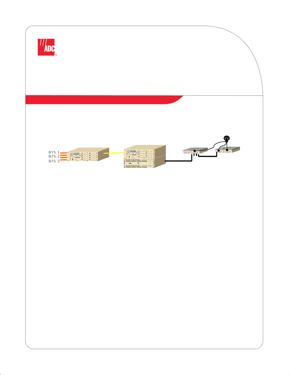
Main Remote Access Unit
The Main Remote Access Unit (MRAU) design allows for easier Band 1 and Band 2
Mix-and-Matching per country and/or market needs. MRAU components are as
shown in the following figure.
Page 8 FlexWave Prism Remote Unit Ins tallation Guide
©
2009 ADC Telecommunications, Inc ADCP-77-072 • Issue 2 • 11/2009
Page 11

Introduction
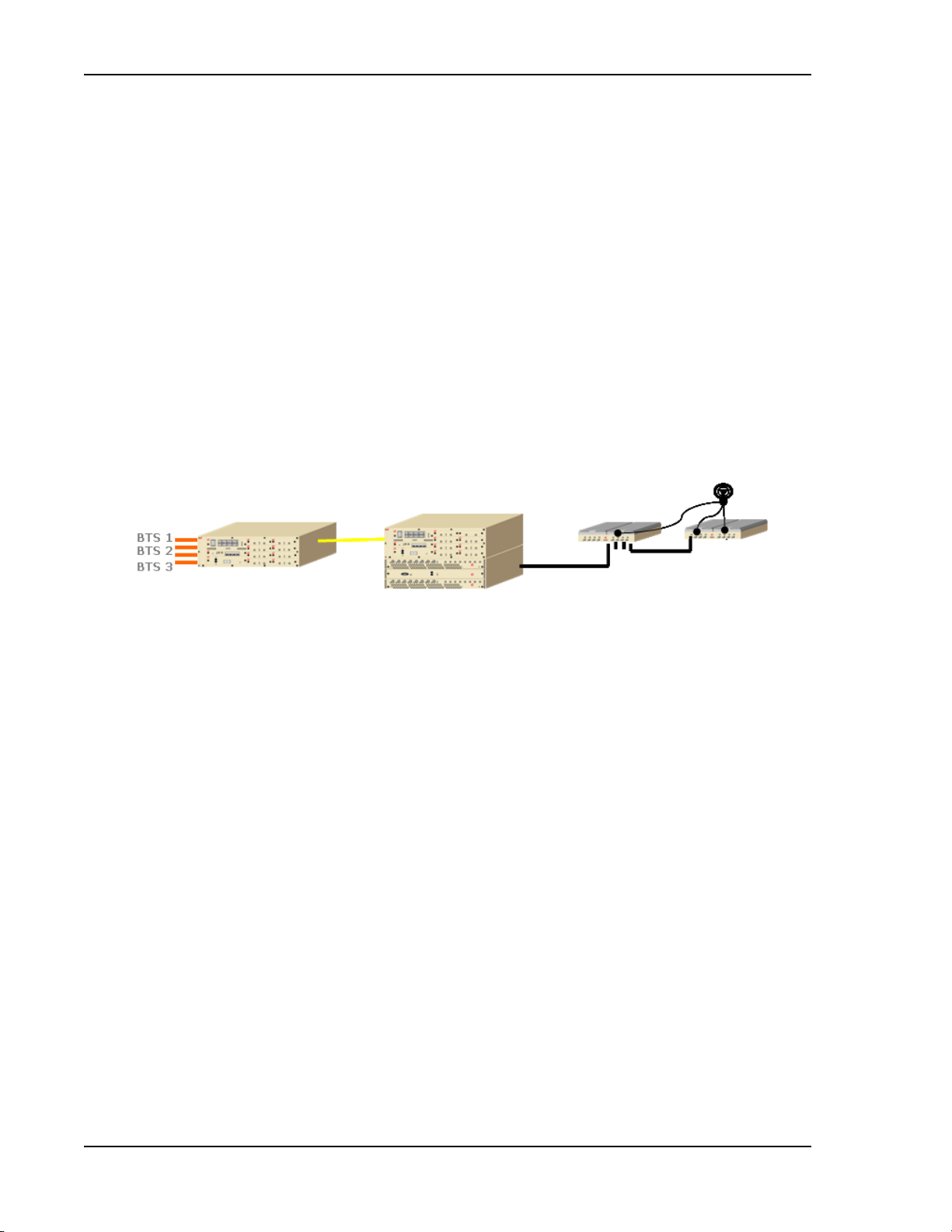
Secondary Remote Access Unit
The Secondary Remote Access Unit (SRAU) design allows for easier Band 1 and
Band 2 Mix-and-Matching per country and/or market needs. SRAU components
are as shown in the following figure.
BTS 1
BTS 1
BTS 1
BTS 2
BTS 2
BTS 2
BTS 3
BTS 3
BTS 3
Band 1 and 2 Boards
RAU pairing examples:
850/1900
700/700 MIMO
800/900 SMR
700 SISO/AWS
800/AWS
Connects to
Main RAU
(MRAU)
FlexWave Prism Remote Unit Install ation Guide Page 9
ADCP-77-072 • Issue 2 • 11/2009 © 2009 ADC Telecommunications, Inc.
Page 12

Introduction
Omni Antenna
The Omni Antenna (4214-M727) supports the following:
• Port 1
– 698-806 MHz (700 LTE)
– 1710-2170 MHz (AWS)
• Port 2
– 806-941 MHz (Cellular/SMR)
– 1850-1990 MHz (PCS)
• Port 3
– 2500-2700 MHz (WiMAX)
The Omni Antenna (see figure below) is a round radome with the following
specifications:
• 8.5-inch diameter
• 1.65-inch height
• 72-inch pigtails that are plenum-rated cables with N (male) connectors
NOTE: Two antennas per RAU is required for MIMO performance.
Page 10 FlexWave Prism Remote Unit Installation Guide
©
2009 ADC Telecommunications, Inc ADCP-77-072 • Issue 2 • 11/2009
Page 13

Installation
INSTALLATION
Follow the steps in the order in which they are presented.
1 Connect the Host single-mode fiber SFPs (1-4) to the DART Remote Unit SFPs
(5-8):
• HU SFP 1 to DRU SFP 5
• HU SFP 2 to DRU SFP 6
• HU SFP 3 to DRU SFP 7
• HU SFP 4 to DRU SFP 8
2 Connect the provided Vdc power cables to the +V and –V power-supply
terminals.
CAUTION! The Power Supply requires 2-20amp 120VAC outlets.
FlexWave Prism Remote Unit Installation Guide Page 11
ADCP-77-072 • Issue 2 • 11/2009 © 2009 ADC Telecommunications, Inc.
Page 14

Installation
3 Connect IF DART QMA cables to IFEU:
a Connect QMA cable from all IF DART FWD OUT connectors to any IFEU FWD
Module IF IN connector.
b Connect QMA cable from all IF DART REV IN connector to any IFEU REV
Module IF OUT connector.
4 Connect F connector CATV cable from IFEU FWD Module Port IF OUT to MRAU
FWD IF IN F connector.
Page 12 FlexWave Prism Remote Unit Installation Guide
©
2009 ADC Telecommunications, Inc ADCP-77-072 • Issue 2 • 11/2009
Page 15

Installation
5 Connect F connector CATV cable from IFEU REV Module Port IF IN to MRAU REV
IF OUT F connector.
6 Connect MRAU and SRAU F FWD and REV connectors:
a Connect F connector CATV jumper cable from MRAU FWD Secondary F
connector to SRAU Secondary FWD F connector.
b Connect F connector CATV jumper cable from MRAU REV Secondary F
connector to SRAU Secondary REV F connector.
FlexWave Prism Remote Unit Installation Guide Page 13
ADCP-77-072 • Issue 2 • 11/2009 © 2009 ADC Telecommunications, Inc.
Page 16

Cascading
CASCADING
You add bands by inserting DART cards and CATV jumper between the Main and
new Secondary RAUs, as shown below. 1 to 16 cascaded Expansion Units support
up to 128 RAU locations.
Page 14 FlexWave Prism Remote Unit Installation Guide
©
2009 ADC Telecommunications, Inc ADCP-77-072 • Issue 2 • 11/2009
Page 17

Specifications
SPECIFICATIONS
RF Specification
Supported Frequency Blocks 2 per Remote Antenna Unit; 1-8 per Host Unit
Bandwidth 1.5 to 75 MHz non-contiguous
Frequency Band Supported 850 Cellular, 1900 PCS, 700
2100 AWS (Future Release)
E-SMR 800/900 (Future Release)
Propagation Delay
System Delay <12 microseconds
Delay Management Digital (Manual or Automatic)
Noise Figure
Noise Figure <12 dB
Input IP3 >-10 dBm
Optical Specifications
Optical Budget 10 dB (Standard); 26 dB (Optional)
Digital Transport Rate 3.072 Gbps
Output Power
Output Power per Band 26 dBm 850MHz Cell
26 dBm 1900MHz PCS
26 dBm 700MHz LTE
26 dBm 2100MHz AWS (future)
Remote Access Unit
Operating Temp -25°C to +50°C
Storage Temperature -40°C to +70°C
Humidity 10% to 90% non-condensing
Dimensions 10.67" x 8.25" x 3.00"
Weight 7.49 Pounds
Host Unit and Dart Remote Unit
Mounting 19- and 23-inch rack
Dimensions (Rack mountable) 5.25" x 19.00" x 19.00"
Weight <25 Pounds
FlexWave Prism Remote Unit Installation Guide Page 15
ADCP-77-072 • Issue 2 • 11/2009 © 2009 ADC Telecommunications, Inc.
Page 18

Specifications
Host Unit and DART Remote Unit Power Requirements
Power Source 21 to 60 VDC floating
Battery Backup UPS
IF Expansion Unit
Mounting 19- and 23-inch rack
Dimensions (Rack mountable) 5.25" x 17.11" x 11.93"
Weight <19.5 Pounds
IF Expansion Unit Power Requirements
Power Source +51 to +57 VDC
Battery Backup UPS
Remote Access Unit
Operating Temp -25°C to +50°C
Storage Temperature -40°C to +70°C
Humidity 10% to 90% non-condensing
Dimensions 11.50" x 9.00" x 3.50"
Weight 7.49 Pounds
Remote Access Unit Power Requirements
Power Source 54 VDC (from IFEU)
Element Management
Embedded EMS Yes
SNMP Based Management Yes
Page 16 FlexWave Prism Remote Unit Installation Guide
©
2009 ADC Telecommunications, Inc ADCP-77-072 • Issue 2 • 11/2009
Page 19

CONTACTING ADC
13944-Q
Contents herein are current as of the date of publication. ADC reserves the right to change the contents
without prior notice. In no event shall ADC be liable for any damages resulting from loss of data,
loss of use, or loss of profits and ADC further disclaims any and all liability for indirect, incidental,
special, consequential or other similar damages. This disclaimer of liability applies to all products,
publications and services during and after the warranty period.
REPRINTS:
www.adc.com/manuals
PDF copies of manuals are available
for downloading at the following link:
PRODUCT INFORMATION AND TECHNICAL ASSISTANCE:
connectivity.tac@adc.com
wireless.tac@adc.com
euro.tac@adc.com
asiapacic.tac@adc.com
ADCP Number:
WRITE:
ADC Telecommunications (S’PORE) PTE, LTD;
100 Beach Road, #18-01, Shaw Towers.
Singapore 189702.
ADC Telecommunications, INC
PO Box 1101,
Minneapolis, MN 55440-1101, USA
ADC European Customer Service, INC
Belgicastraat 2,
1930 Zaventem, Belgium
77-079
PHONE :
U.S.A. or CANADA
Sales: 1-800-366-3891
Extension 73000
Technical Assistance: 1-800-366-3891
Connectivity Extension: 73475
Wireless Extension: 73476
EUROPE
Sales Administration: +32-2-712-65 00
Technical Assistance: +32-2-712-65 42
EUROPEAN TOLL FREE NUMBERS
Germany: 0180 2232923
UK: 0800 960236
Spain: 900 983291
France: 0800 914032
Italy: 0800 782374
ASIA/PACIFIC
Sales Administration: +65-6294-9948
Technical Assistance: +65-6393-0739
ELSEWHERE
Sales Administration: +1-952-917-3000
Technical Assistance: +1-952-917-3475
Contacting ADC
FlexWave Prism Remote Unit Installation Guide Page 17
ADCP-77-072 • Issue 2 • 11/2009 © 2009 ADC Telecommunications, Inc.
Page 20

Website: www.adc.com
 Loading...