

Page 1

Cellworx STN
Release 3.1 GUI Users Manual
Issue 1
February 2001
1152700 Rev A
Page 2

Page 3

Release 3.1 GUI Users Manual
Issue 1
February 2001
1152700 Rev A
Page 4

1152700• Issue 1 • February 2001 • Preface
COPYRIGHT
2000, ADC Telecommunications, Inc.
All Rights Reserved
Printed in the U.S.A.
REVISION HISTORY
ISSUE DATE REASON FOR CHANGE
Issue 1 02/2001 Phase 3.1 release features added, (622 CRS)
TRADEMARK INFORMATION
ADC and ADC Telecommunications are registered trademarks of ADC Telecommunications, Inc.
Cellworx is a trademark of ADC Telecommunications, Inc.
DISCLAIMER OF LIABILITY
Contents herein are current as of the date of publication. ADC reserves the right to change the contents without prior
notice. In no event shal l ADC be l ia ble for any dam ag es r esul ting fro m lo ss o f data , lo ss of use, o r l oss o f pr ofi ts
and ADC further disclaim s any and al l liability for indirect, incidental, special, consequential or other similar
damages. This disclaimer of liability applies to all products, publications and services during and after the
warranty period.
This publication may be verified at any time by contacting ADC’s Technical Assistance Center at 1-800-366-3891,
extension 54878 (in U.S.A. or Canada) or 1-972-680-4878 (outside U.S.A. and Canada), or by writing to ADC
Telecommunications, Inc., Attn: Technical Assistance Center, Mail Station #77, P.O. Box 1101, Minneapolis, MN
55440-1101, U.S.A.
ADC Telecommunications, Inc.
P.O. Box 1101, Minneapolis, Minnesota 55440-1101
In U.S.A. and Canada: 1-800-366-3891
Outside U.S.A. and Canada: (952) 938-8080
Fax: (952) 946-3292
Page ii
© 2000, ADC Telecommunications, Inc.
Page 5

TABLE OF CONTENTS
Content Page
ABOUT THIS MANUAL................................................................................................................................VII
REVISION HISTORY LIST............................................................................................................................VII
LIST OF CHANGES ....................................................................................................................................VII
TRADEMARK INFORM ATION........................................................................................................................VII
RELATED PUBLICATIONS............................................................................................................................VII
ADMONISHMENTS....................................................................................................................................VII
GENERAL SAFETY PRECAUTIONS.................................................................................................................VIII
FCC COMPLIANCE STATEMENT .....................................................................................................................IX
DOC COMPLIANCE.....................................................................................................................................IX
FDA COMPLIANCE .....................................................................................................................................IX
COMPLIANCE ................................................................................................................................IX
SAFETY
NEBS COMPLIANCE ...................................................................................................................................IX
ISO 9000 COMPLIANCE...............................................................................................................................IX
REFERENCES............................................................................................................................................X
LIST OF ACRONYMS AND ABBREVIATI ONS ......................................................................................................XII
1152700 • Issue 1 • February 2001 • Preface
PREFACE
SECTION 1
INTRODUCTION
Content Page
1. GENERAL........................................................................................................................................... 1-1
2. USER INTERFACES............................................................................................................................... 1-2
A. NMIC RS232 Interface........................................................................................................... 1-3
B. NMIC EIM RJ45 E thernet Interf ace............................................................................................ 1-3
C. NMIC Serial Equipment Port ................................................................................................... 1-4
3. CELLWORX STN SYSTEM SOFTWARE........................................................................................................ 1-4
A. NMIC Graphical User Interface (GUI)......................................................................................... 1-4
GUI Screen Icon Definitions ....................................................................................... 1-5
GUI Menu Structure and Utilization .............................................................................. 1-8
X-Terminal Keyboard Functions..................................................................................1-11
Manipulating the GUI Net work Layout on an X-Terminal Screen ..........................................1-12
4. REMOTE MANAGEMENT CAPABILITIES......................................................................................................1-12
A. Real Time Alarm and trap Screens.....................................................................................................1-13
© 2000, ADC Telecommunications, Inc.
Page iii
Page 6

1152700• Issue 1 • February 2001 • Preface
Content Page
1. GENERAL........................................................................................................................................... 2-1
2. USING A TOP DOCUMENT....................................................................................................................... 2-1
ALPHABETICAL TASK I NDEX LIST ................................................................................................................ 2-3
INDEXED TASK LI ST ...........................................................................................................................IXL-001
TURN UP A NEW CELLWORX STN RING NETWORK .....................................................................................NTP-002
ADD A CELLWORX STN NODE TO AN IN SERVICE RING NETWORK...................................................................NTP-003
ADD A SECOND NETWORK ELEMENT TO AN IN SERVICE STAND-ALONE TERMINAL
TO CREATE A RING NETWORK .....................................................................................................NTP-004
TURN UP (PROVISION) CELLWORX STN EXPANSION SHELVES.......................................................................N TP-005
PROVISION NODE PARAMETERS ...........................................................................................................NTP-006
DISPLAYING STATUS AN D ALARMS........................................................................................................NTP-007
RETRIEVE PER FORMANCE MONITORING STATISTICS..................................................................................NTP-008
ADDING SERVICES TO A CELLWORX STN NODE.........................................................................................NTP-009
DELETE A CELLWORX STN NODE...........................................................................................................NTP-010
CONDUCT ACCEPTANCE TESTS ON CELLWORX STN NODE ............................................................................NTP-011
PERFORM ROUTINE AND NON-ROUTINE MAINTENANCE...............................................................................NTP-012
PROVISION ATM VP AND VC CONNECTIONS..............................................................................................NTP-013
MONITORING TH E NETWORK................................................................................................................NTP-014
ADMINISTRATIVRE TASKS...................................................................................................................NTP-015
CELLWORX UPGRADE PROCEDURES......................................................................................................NTP-016
POWER UP A CELLWORX STN NODE.......................................................................................................DLP-700
CONNECT FIBERS TO OPT ICAL CARDS ....................................................................................................DLP-701
CONNECT VT1OO TO NMIC RS-232 PORT AND MODIFY NMIC IP ADDRESS........................................................DLP-702
LOGON TO REMOTE NODE CRAFT SESSION VIA TELNET FROM GUI ................................................................DLP-703
CONNECT NMS OR X-TERMINAL TO THE NMIC EIM SNMP/GUI PORT ...............................................................DL P-704
LAUNCH THE GRAPHI CAL USER INTERFACE (GUI ) ......................................................................................DLP-705
PERFORM DISCOVERY ON A NEW CELLWORX STN RING NETWORK ...............................................................DLP-706
TIME AND DATE................................................................................................................................DLP-707
CREATE A N ATM OR CES CONNECTION...................................................................................................DLP-708
CONFIGURE OR DELETE A TRAFFIC CONTRACT..........................................................................................DLP-709
VIEW CONNECTIONS ..........................................................................................................................DLP-710
LOG OFF OF CELLWORX STN GRAPHICAL USER INTERFACE..........................................................................DLP-711
ADD EXPANSION NODES (STN-EPS)........................................................................................................DLP-712
DISPLAY NETWORK ALARM SUMMARY...................................................................................................DLP-713
CONFIGURE SERVICE PROVIDER PROFILE................................................................................................DLP-714
VIEW RING RESOURCE USAGE..............................................................................................................DLP-715
VIEW FIBER BANDWIDTH USAGE...........................................................................................................DLP-716
CONFIGURE NE ALARM THRESHOLD ......................................................................................................DLP-717
REFRESH TOPOLOGY .........................................................................................................................DLP-718
FORCE NETWOR K DISCOVERY..............................................................................................................DLP-719
SOFTWARE SELECTION.......................................................................................................................DLP-720
SECTION 2
OPERATION AND MAINTENANCE
(continued)
Page iv
© 2000, ADC Telecommunications, Inc.
Page 7

1152700 • Issue 1 • February 2001 • Preface
SECTION 2
OPERATION AND MAINTENANCE, CONTINUED
Find Your Job in the List Below Then Go To
ABOUT NE.......................................................................................................................................DLP-721
NMIC SYSTEM FILE REPLICATION..........................................................................................................DLP-722
CHANGE CONFIGURATION/TEST ON AN EXISTING CONNECTION ....................................................................DLP-723
NMIC PROTECTIO N ............................................................................................................................DLP-724
NMIC PROTECTIO N R ESTORATION.........................................................................................................DLP-725
SET / RETRIEVE OPTICAL PORT PERFOR MANCE MONITORING STATISTICS .......................................................DLP-726
SET / RETRIEVE T3 TMUX PERFORMANCE MONITORING STATISTICS...............................................................DLP-727
SET / RETRIEVE T3 CRS PORT PERFORMANCE MONITORING STATISTICS.........................................................DLP-728
SET / RETRIEVE T1/E1 MULTI 1 CRS PERFORMANCE MONITORI N G STATISTICS ................................................DLP-729
RETRIEVE NETWORK DATA COLLECTION (NDC) STATISTICS..........................................................................DLP-730
RING UPGRADE PROCEDURE................................................................................................................DLP-731
SET / RETRIEVE FT1 FRS PERFORMANCE MONITORING STATISTICS ...............................................................DLP-732
SET / RETRIEVE FE1 FRS PERFORMANCE MONITORING STATISTICS ...............................................................DLP-733
SOFTWARE FALLBACK........................................................................................................................DLP-734
HELP ...........................................................................................................................................DLP-735
REVERT TO SAVED ICON LAYOUT ..........................................................................................................DLP-736
ADD A RING NETWORK ELEMENT ..........................................................................................................DLP-737
ADD A SECOND NETWORK ELEMENT ......................................................................................................DLP-738
DELETE CONNECTIONS.......................................................................................................................DLP-739
DELETE A CELLWORX STN SHELF..........................................................................................................DLP-740
RETRIEVE LOGS FROM THE NMIC VIA FTP ...............................................................................................DLP-741
RETRIEVE COMPRESSED LOGS FROM THE NMIC VIA FTP.............................................................................DLP-742
REFLASH BOOT IM AG E .......................................................................................................................DLP-744
SYSTEM DATABASE ACCESS ................................................................................................................DLP-745
DELETE A CELLWORX STN EXPANSION SHELF (EPS)...................................................................................DLP-746
SET E1 MULTI 1 CARD CONFIGURATION..................................................................................................DLP-747
SET SC CARD CONFIGURATION (IP ADDRESS, CRAFT INTERFACE)..................................................................DLP-748
SET SHELF TIMING RESOURCE .............................................................................................................DLP-749
SET SHELF HOUSEKEEPING ALARM CONFIGURATION..................................................................................DLP-750
SET 622 RING CARD CONFIGURATION.....................................................................................................DLP-751
SET 155 SM/MM CRS CARD CONFIGURATION ...........................................................................................DLP-752
SET T3 CRS CARD CONFIGURATION .......................................................................................................DLP-753
SET T3 TMUX MULTI 1 AND TMUX EXP CONFIGURATION..............................................................................DLP-754
SET T1 MULTI 1 CARD CONFIGURATION .................................................................................................DLP-755
SET 155 RING INTERFACE CARD CONFIGURATION......................................................................................DLP-758
SET 2488 RING INTERFACE CARD CONFIGURATION....................................................................................DLP-756
RETRIEVE SC CARD STATUS.................................................................................................................DLP-757
RETRIEVE 622 RIC STATUS..................................................................................................................DLP-759
RETRIEVE 155 CRS STATUS.................................................................................................................DLP-760
RETRIEVE T3 CRS CARD STATUS...........................................................................................................DLP-761
RETRIEVE T3 TMUX MULTI 1 CARD STATU S .............................................................................................DLP-762
© 2000, ADC Telecommunications, Inc.
Page v
Page 8

1152700• Issue 1 • February 2001 • Preface
SECTION 2
OPERATION AND MAINTENANCE, CONTINUED
Find Your Job in the List Below Then Go To
RETRIEVE 155 RING INTERFACE CARD STATUS.........................................................................................DLP-763
RETRIEVE T1 MULTI 1 CARD STATUS......................................................................................................DLP-764
CONFIGURE CARD PROTECTION GROUPS ................................................................................................DLP-765
PERFORM DIAGNOSTICS ON OPTICAL CARDS ...........................................................................................DLP-766
SET SYSTEM IDEN TIFIER ....................................................................................................................DLP-767
SET CRAFT USER CONFI GURATION .......................................................................................................DLP-768
SET CRAFT MENU CONFIGURATION........................................................................................................DLP-769
HARDWARE INVENTORY .....................................................................................................................DLP-770
INITIATE A PRO TECTION SWITCH...........................................................................................................DLP-771
LOOPBACK TEST ...............................................................................................................................DLP-772
CARD AND SHELF RESET.....................................................................................................................DLP-773
VIEWING AND EDITING THE NMIC IP ADDRESS..........................................................................................DLP-774
ADD OR EDIT AN SNMP T R AP HOST ON THE NMIC...................................................................................... DLP-775
ALARM CUT-OFF (ACO) ......................................................................................................................DLP-776
REMOVE AND/OR REPLACE CELLWORX CARDS.........................................................................................DLP-777
ENDING A GUI SESSION FOLLO WING AN ABNORMAL SESSION ENDING............................................................DLP-778
RETRIEVE 2488 RING INTERFACE CARD STATUS........................................................................................DLP-779
PHASE 2.0 TO 3.0 SOFTWARE UPGRADE PROCEDURE .................................................................................DLP-780
REMOVING A NMIC CARD F ROM THE SHELF.............................................................................................DLP-781
FTP DATABASE FILES OFF OF NMIC .......................................................................................................DLP-782
ADD/DELETE GUI USERS OR CHANGE GUI USER LEVEL SECURITY..................................................................DLP-783
SET FE1 FRS CARD CONFIGURATION......................................................................................................DLP-784
SET FT1 FRS CARD CONFIGURATION......................................................................................................DLP-785
CREATE A FRAME RELAY CONNECTION ...................................................................................................DLP-786
CREATE AN ATM MULTICAST CONNECTION ..............................................................................................DLP-787
RETRIEVE FT1 FRS CARD STATUS .........................................................................................................DLP-788
RETRIEVE FE1 FRS CARD STATUS .........................................................................................................DLP-789
CREATING AN ATM BUNDLED VC MULTICAST CONNECTION. .........................................................................DLP-790
ADD A LEAF ENDPOINT TO AN IN-SERVICE CONNECTION..............................................................................DLP-791
SET T3 CES CARD CONFIGURATION........................................................................................................DLP-792
RETRIEVE T3 CES CARD STATUS. ..........................................................................................................DLP-793
SET / RETRIEVE T3 CES PORT PERFORMAN CE MONITORING STATISTICS. ........................................................DL P-794
PHASE 3.0 TO 3.1 SOFTWARE UPGRADE PROCEDURE .................................................................................DLP-795
RETRIEVE 622 CRS STATUS.................................................................................................................DLP-796
SET 622 SM CRS CARD CONFIGURATION.................................................................................................DLP-797
SOFTWARE FALLBACK FROM RELEASE 3.1 TO RELEASE 3.0.........................................................................DL P-798
TROUBLE ANALYSIS PROCEDURE ..........................................................................................................TAP-100
Page vi
© 2000, ADC Telecommunications, Inc.
Page 9

1152700 • Issue 1 • February 2001 • Preface
SECTION 3
GENERAL INFORMATION
Content Page
1. WARRANTY/SOFTWARE................................................................................................................... 3-1
2. REPAIR/EXCHANGE POLICY............................................................................................................... 3-1
3. REPAIR CH AR GES .......................................................................................................................... 3-2
4. REPLACEMENT/SPARE PRODUCTS...................................................................................................... 3-2
5. RETURNED MATERIAL..................................................................................................................... 3-2
6. SYSTEM INTEGRATION SERVICES....................................................................................................... 3-3
7. CUSTOMER SUPPORT SERVICES ........................................................................................................ 3-3
© 2000, ADC Telecommunications, Inc.
Page vii
Page 10

1152700• Issue 1 • February 2001 • Preface
ABOUT THIS MANUAL
This manual provides the system administrator with information necessary to turn up and test the
Cellworx Service Transport Node (STN), and/or services, as well as configure connections and monitor
the network using the CellworxVision Graphical User interface (GUI). Information provided within this
document deals primarily with the Phase 3.1 design features of the Cellworx STN system.
Trademark Information
The following trademarks are documented in this manual:
ADC and ADC Telecommunications are registered trademarks of ADC Telecommunications Inc.
Cellworx is a registered trademark of ADC Telecommunications Inc.
Open View is a registered trademark of Hewlett-Packard.
SRTS – Synchronous Residual Time Stamp is a patent of Bell Communications Research, N ov 9, 1993
Related Publications
Listed below are all of the related manuals and their publication numbers. Copies of these publications can
be ordered by contacting the ADC Technical Assistance Center at 1-800-366-3891 extension 63434 (in
U.S.A. or Canada) or 612-946-3434 (outside U.S.A. and Canada).
Title/Description Part Number
Application and Engineering Guide 3.1 1152699
Contains an introduction to the ADC Cellworx STN system, hardware and software
descriptions, applications, and engineering information required for system deployment.
Craft User’s Manual 3.1 1152703
Contains information required for provisioning, operation, and administration of the
Cellworx STN system through the craft access. Information includes detecting and isolating
alarms, and turn up of features over the entire network.
System Description Manual 3.1 1152712
Combines information from the Users Manual, Installation Manual, and Applications
Engineering Manual to provide introductory information and a general overview of the
Cellworx STN system.
Cellworx CLEI Code Guide 1112344
Lists all CLEI codes used to order Cellworx equipment.
Page viii
© 2000, ADC Telecommunications, Inc.
Page 11

Admonishments
Important safety admonishments are used throughout this manual to warn of possible hazards
to persons or equipment. An admonishment identifies a possible hazard and then explains what
may happen if the hazard is not avoided. The admonishments — in the form of Dangers,
Warnings, and Cautions — must be followed at all times. These warnings are flagged by use of
the triangular alert icon (seen below), and are listed in descending order of severity of injury or
damage and likelihood of occurrence.
Danger: Danger is used to indicate the presence of a hazard that will cause severe personal
injury, death, or substantial property damage if the hazard is not avoided.
Warning: Warning is used to indicate the presence of a hazard that can cause severe personal
injury, death, or substantial property damage if the hazard is not avoided.
Caution: Caution is used to indicate the presence of a hazard that will or can cause minor
personal injury or property damage if the hazard is not avoided.
1152700 • Issue 1 • February 2001 • Preface
General Safety Precautions
Danger: Do not look into the ends of optical fibers. Exposure to invisible LASER radiation may
cause serious retinal damage or even blindness. Verify the optical source is disabled through
the use of an optical power meter before handling optical fibers.
Caution: Use caution when routing wires and cables. Avoid severe bending and routing over
sharp edges. Use grommet material when possible to avoid wear on cable insulation.
Caution: Allow sufficient fiber length to permit routing without severe bends. Fibers may be
permanently damaged, or signal degradation may be experienced if fibers are bent or curved to
a radius of less than 1.5 inches (3.81 cm).
Caution: Modules can be damaged by electrostatic discharge. Before handling any modules
connect your wrist to an equipment ground using an approved anti-static wrist strap. Ensure
that all uninstalled modules are stored in anti-static packing material. When working with
modules, always place the module on an electrically grounded approved anti-static mat.
Caution: Using excessive force when seating cards and modules into the backplane may result
in physical or severe electrical damage to the backplane pins or module connectors, and if
power is applied, may result in serious electrical damage to both the modules or the backplane
© 2000, ADC Telecommunications, Inc.
Page ix
Page 12

1152700• Issue 1 • February 2001 • Preface
FCC COMPLIANCE STATEMENT
Class A
The Cellworx STN System complies with the requirements for class A digital device per Part
15 of the FCC Rules.
Warning: This equipment has been tested and found to comply with the limits for a Class A
digital device, pursuant to part 15 of the FCC Rules. These limits are designed to provide
reasonable protection against harmful interference when the equipment is operated in a
commercial environment. This equipment generates, uses, and can radiate radio frequency
energy and, if not installed and used in accordance with the instruction manual, may cause
harmful interference to radio communications. Operation of this equipment in a residential
area is likely to cause harmful interference in which case the user will be required to correct
the interference at his own expense.
DOC Compliance
This equipment does not exceed Class A limits for radio emission for digital apparatus, set out
in the radio interference regulation of the authorization methods of Industry Canada.
Operation in a residential area may cause unacceptable interference to TV and radio reception
requiring the owner or operator to take whatever steps are necessary to correct the
interference.
FDA Compliance
This product uses a Class 1 LASER according to FDA Rules. This product conforms to all
applicable standards of 21 CFR 1040.
Safety Compliance
UL listed for use in the U.S. and Canada.
IEC 950 (1991) Second Edition with Amdts. No. 1 (1992), 2 (1993), 3 (1995), and 4 (1996)
EN60950 (1992) with Amdts. No. 1 (1993), 2 (1993), 3 (1995, 4 (1997), and No.11 (1997); and
with National Differences as specified in the CB Test Report 99RT07840-121698.
The Cellworx STN system complies with EN 55022:1995, IEC 801-2:1991, IEC 801-3:1984
and draft IEC 801-3-1990, and IEC 801-4:1988.
The Cellworx STN system complies to all the applicable EC directives of the European Union
and is CE marked.
NEBS Compliance
The Cellworx STN system is fully NEBS compliant.
Page x
© 2000, ADC Telecommunications, Inc.
Page 13

ISO9000 Compliance
ADC Telecommunications Inc. is ISO 9001 certified.
STANDARDS
The following listing is a bibliography of applicable documents:
ANSI/IEEE Std 802.1D,1993 Edition.
ANSI T1.403-1989, Carrier to Customer Installation: T1 Metallic Interface, February 22, 1989
ATM UNI specification 3.1, ATM Forum
Bellcore GR-253-CORE, Synchronous Optical Network (SONET) Transport Systems:
Bellcore GR-1110-CORE, Broadband Switching System Generic Requirements,
Bellcore GR-1113-CORE, Asynchronous Transfer Mode (ATM) and ATM Adaptation
1152700 • Issue 1 • February 2001 • Preface
Common Generic Criteria, Issue 2, 12/95
Issue 1, 9/94, Revision 3, 4/96
Layer (AAL) Protocols, Bellcore.
Bellcore GR-1117-CORE, Generic Requirements for Exchange PVC CRS Customer
Network Management Service, Bellcore.
Bellcore GR-1244-CORE, Clocks for the Synchronized Network: Common Generic
Criteria, Bellcore.
Bellcore GR-1248-CORE, “Generic Requirements for Operations of ATM Network
Elements (NEs),” Issue 3, 8/96
Bellcore GR-1400-CORE, SONET Dual-fed Unidirectional Path Switched Ring (UPSR)
Equipment Generic Criteria, Bellcore.
Bellcore GR-20-CORE, Generic Requirements for Optical Fiber and Optical Fiber Cable,
Bellcore.
Bellcore GR-253-CORE, SONET Transport Systems: Common Criteria, Bellcore.
Bellcore GR-2837-CORE, “ATM Virtual Path Functionality in SONET Rings—Generic
Criteria,” Issue 2, 12/95
Bellcore GR-2842-CORE, “ATM Service Access Multiplexer (SAM) Generic
Requirements,” Issue 1, 11/94
Bellcore GR-2848-CORE, Broadband Multi-service UNI Generic Requirements, Bellcore.
Bellcore GR-436-CORE, Digital Network Synchronization Plan, Bellcore.
Bellcore TR-TSY-000496, Issue 2, September 1989, Supplement 1, September 1991
© 2000, ADC Telecommunications, Inc.
Page xi
Page 14

1152700• Issue 1 • February 2001 • Preface
The ATM Forum ATM User-Network Interface (UNI), Specification, Version 3.1
NFOEC, Volume 2 1995, pg 445. “A Comparative Analysis of 2 Fiber and
NFOEC, Volume 3 1995, pg 885. “SONET Operations Networking; The
RFC-1406, Definitions for Managed Objects for the T1 and E1 Interface
RFC-1407, Definitions for Managed Objects for the T3 and E3 Interface
ITU I.350
ITU I.371
ITU I.610
Bellcore TA-1230
ITU M.3010
ITU M.3020
ITU M.3100
ITU M.3180
4 Fiber Bi Directional Line Switched Rings.”
Key to the Future.”
Types, IETF.
Types, IETF.
TA-NWT-000487, Generic Requirements for Electronic Equipment Cabinets,
Bellcore.
TA-TSV-1408, Generic Requirements for Exchange PVC Cell Relay Service,
Bellcore.
TA-TSV-1409, Generic Requirements for Exchange Access PVC Cell Relay
Service, Bellcore.
TR-NWT-000063, Network Equipment Building System (NEBS) Generic
Equipment Requirements, Bellcore.
TR-NWT-000078, Generic Physical Design Requirements for Telecommunications
Products and Equipment, Bellcore.
TR-NWT-000468, Reliability Assurance Practices for Optoelectronic Devices in
Central Office Applications, Bellcore.
TR-NWT-000496, SONET ADM Equipment Generic Criteria, Bellcore.
TR-NWT-000499, Transport Systems Generic Requirements (TSGR): Common
Requirements, Bellcore.
TR-NWT-000815, OTGR Section 2.3: Network Element and Network System
Security, Bellcore.
TR-NWT-000930, Generic Requirements for Hybrid Microelectronics Used in
Telecommunications Equipment, Bellcore.
TA-NWT-000983, Reliability Assurance Practices for Optoelectronic Devices in
TR-NWT-001112, Broadband-ISDN User to Network and Network Node Interface
Page xii
© 2000, ADC Telecommunications, Inc.
Loop Applications, Bellcore.
Physical Layer Generic Criteria, Bellcore.
Page 15

1152700 • Issue 1 • February 2001 • Preface
TR-TSV-000772, Generic System Requirements in Support of Switched Multi-
Megabit Data Service, Bellcore.
TR-TSV-001369, Generic Requirements for Frame Relay PVC Exchange Service,
Bellcore.
TR-TSV-001370, Generic Requirements for Exchange Access Frame Relay PVC
Service, Bellcore.
TR-TSY-000454, Supplier Documentation for Network Elements, Bellcore.
List of Acronyms and Abbreviations
The acronyms and abbreviations used in this manual are detailed in the following list:
155 CRS Dual port Optical Carrier card providing Cell Relay Service in a
concatenated payload at a data rate of 155Mbps
155 RIC Optical Carrier Ring Interface Card providing cell relay service in a
concatenated payload at a data rate of 155Mbps
622 RIC Optical Carrier Ring Interface Card providing cell relay service in a
concatenated payload at a data rate of 622Mbps
2488 RIC Optical Carrier Ring Interface Card providing cell relay service in a
concatenated payload at a data rate of 2488Mbps
ABR Available Bit Rate
ADM Add / Drop Multiplexer
AIC Access Interface Card
AIS Alarm Indication Signal
APS Automatic Protection Switching
ATM Asynchronous Transfer Mode
B-ICI Broadband Inter-Exchange Carrier Interface
BPS Bits Per Second
CAC Connection Admission Control
CBR Constant Bit Rate
CDV Cell Delay Variation
CDVT Cell Delay Variation Tolerance
CES Circuit Emulation Service
CIR Committed Information Rate
CO Central Office
CPE Customer Premise Equipment
CRS Cell Relay Service
CTD Cell Transfer Delay
DCC Data Communications Channel
E1 TMUX Multi 1 A 16 E1 port card that converts digital signals into ATM streams
EIM Electrical Interface Module
EPS Expansion Shelf
ESF Extended Superframe
FRS Frame Relay Service
FTP File Transfer Protocol
GNE Gateway Network Element
GUI Graphical User Interface
IP Internet Protocol
© 2000, ADC Telecommunications, Inc.
Page xiii
Page 16

1152700• Issue 1 • February 2001 • Preface
LAN Local Area Network
LEC Local Exchange Carrier
LTE Line Terminating Equipment
msec millisecond
NDC Network Data Collection
NE Network Element
NIC Network Interface Card
NMIC Network Management Interface Card
NMS Network Management System
NNI Network to Network Interface
NPC Network Parameter Control
OAM&P Operations, Administration, Maintenance, and Provisioning
OS Operations System
PCR Peak Cell Rate
PEIM Protection EIM
PTE Path Terminating Equipment
PVC Permanent Virtual Circuit
QoS Quality of Service
RIC Ring Interface Card
SAM Service Access Multiplexer
SC Shelf Controller card
SCR Sustained Cell Rate
SDH Synchronous Digital Hierarchy
SEPIC Shelf ExPansion Interface Card
SNMP Simple Network Management Protocol
SONET Synchronous Optical NETwork
SPE Synchronous Payload Envelope
SRTS Synchronous Residual Time Stamp (patent 5260978 Bell Comm. Research)
STM Synchronous Transport Mode
STN Service Transport Node
STS Synchronous Transport Signal
STS-3c Concatenated STS-3 signal (one payload)
SVC Switched Virtual Circuit
T1 Digital Signal Level 1
T1 TMUX Multi 1 A 16 DS1 port card that converts digital signals into ATM streams
T3 Digital Signal Level 3
T3 CES Three port Digital Subscriber line card providing Circuit Emulation
T3 CRS Three port Digital Subscriber line card providing Cell Relay Service at a
T3 TMUX Multi 1 A single DS3 port line card providing individual DS1 channel multiplexing
TC Transmission Convergence
TCA Threshold Crossing Alert
TDM Time Division Multiplexer
TEIM Terminating Electrical Interface Module
TFTP Trivial File Transfer Protocol
TID Target Identifier
TMN Telecommunication Management Network
Service at a data rate of 45Mbps
data rate of 45Mbps
Page xiv
© 2000, ADC Telecommunications, Inc.
Page 17

UBR Unspecified Bit Rate
UNI User Network Interface
UPC Usage Parameter Control
UPSR Unidirectional Path Switch Ring
UVPSR Unidirectional Virtual Path Switch Ring
VC Virtual Channel
VCC Virtual Channel Connection
VP Virtual Path
VPC Virtual Path Connection
VT Virtual Tributary
W/P Working/Protect
1152700 • Issue 1 • February 2001 • Preface
© 2000, ADC Telecommunications, Inc.
Page xv
Page 18

SECTION 1
INTRODUCTION
CONTENT..........................................................................................................................PAGE
1. GENERAL ...........................................................................................................................1
2.USER INTERFACES.................................................................................................................2
A.NMIC RS232 Interface........................................................................................................3
B.NMIC EIM RJ45 Ethernet Interface.........................................................................................3
C.NMIC Serial Equipment Port ................................................................................................4
3.CELLWORX STN SYSTEM SOFTWARE..........................................................................................4
A.NMIC Graphical User Interface (GUI) ......................................................................................4
4. REMOTE MANAGEMENT CAPABILITIES ..................................................................................... 13
A.Real Time Alarm and trap Screens ...................................................................................... 14
1152700• Issue 1 • February 2001 • Section 1 Introduction
GUI Screen Icon Definitions......................................................................................5
GUI Menu Structure and Utilization.............................................................................8
X-Terminal Keyboard Functions............................................................................... 12
Manipulating the GUI Net work Layout on an X-Terminal Screen........................................ 12
1. GENERAL
This section provides information on the Cellworx Service Transport Node’s (STN)
Graphical User interface (GUI) and alarm monitoring capabilities. Information in
this document relates to the Release 3.1 design features of the Cellworx STN
system. Future revisions of this document will cover added features and
enhancements to the system and/or software.
The Cellworx STN system has been designed to accelerate the migration of
networks to support broadband services. It is an Add/Drop Multiplexer (ADM)
utilizing Asynchronous Transfer Mode (ATM) technologies to support access and
delivery of emerging and legacy services. Through the use of simple transport
provisioning, the Cellworx STN enables broadband services on an ATM backbone
to coexist within the TDM infrastructure. A single platform is used to both deploy
new services to thousands of customers, and provide significant bandwidth savings
in existing networks. At the same time, it provides the utility and survivability that
service providers have come to expect from true Telecom-oriented SONET
products.
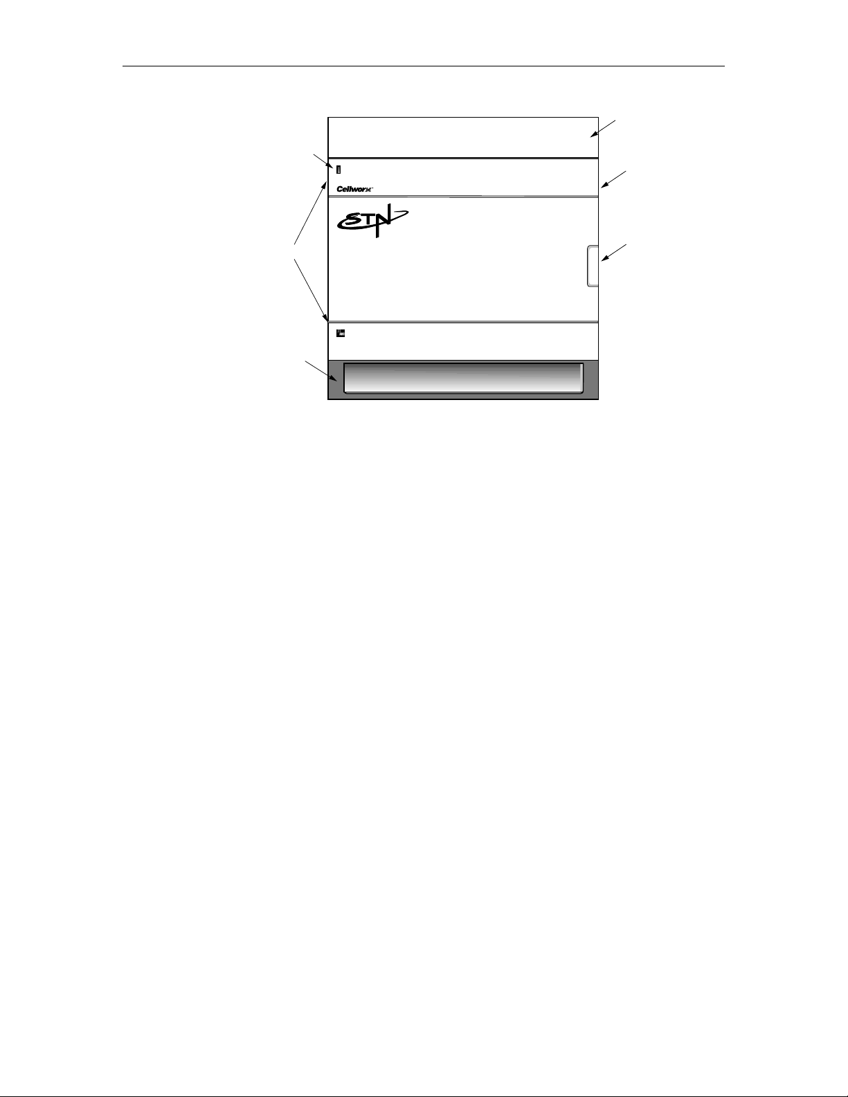
The Cellworx STN shelf is shown in Figure 1-1. It is available in a 19-inch or a 23inch rack mount shelf that has specific card slot assignments for the Ring Interface
Cards (RICs), Network Management Interface Cards (NMICs), and Shelf
Controller cards (SCs). The intent of specific slot locations is to maximize bus
performance and the number of working and protect pairs. The Cellworx STN can
be used as a collocated or remote Expansion node utilizing 622, 155 or T3 CRS
cards as links to a ring node to provide subscriber fan out or remote access
capabilities to a ring. Certain card slots are keyed to prevent the installation of
wrong card types into those slots. The remainder of the slots can accept any Access
Interface Card (AIC) provided the proper Electrical Interface Module (EIM) is
installed at the rear of the shelf for that AIC service type.
© 2000 ADC Telecommunications, Inc.
Page 1-1
Page 19
1152700• Issue 1 • February 2001 • Section 1 Introduction
SHELF
ALARM
INDICATOR
DOOR
HINGES
LOWER AIR INTAKE/
CABLE ROUTING TRAY
Figure 1-1. Cellworx STN Shelf
UPPER HEAT BAFFLE/
FIBER MANAGEMENT TRAY
ESD GROUND JACK
DOOR
LATCH
10479-C
2. USER INTERFACES
The Network Management Interface Controller (NMIC) shown in Figure 1-2
provides a common ring and element management system platform where all
aspects of network management are performed. The NMIC houses the operating
system and application software for each node and card to provide Fault,
Configuration, Performance, and Security management functions based on TMN
principles at the Element Management Layer.
Page 1-2
© 2000, ADC Telecommunications, Inc.
Page 20
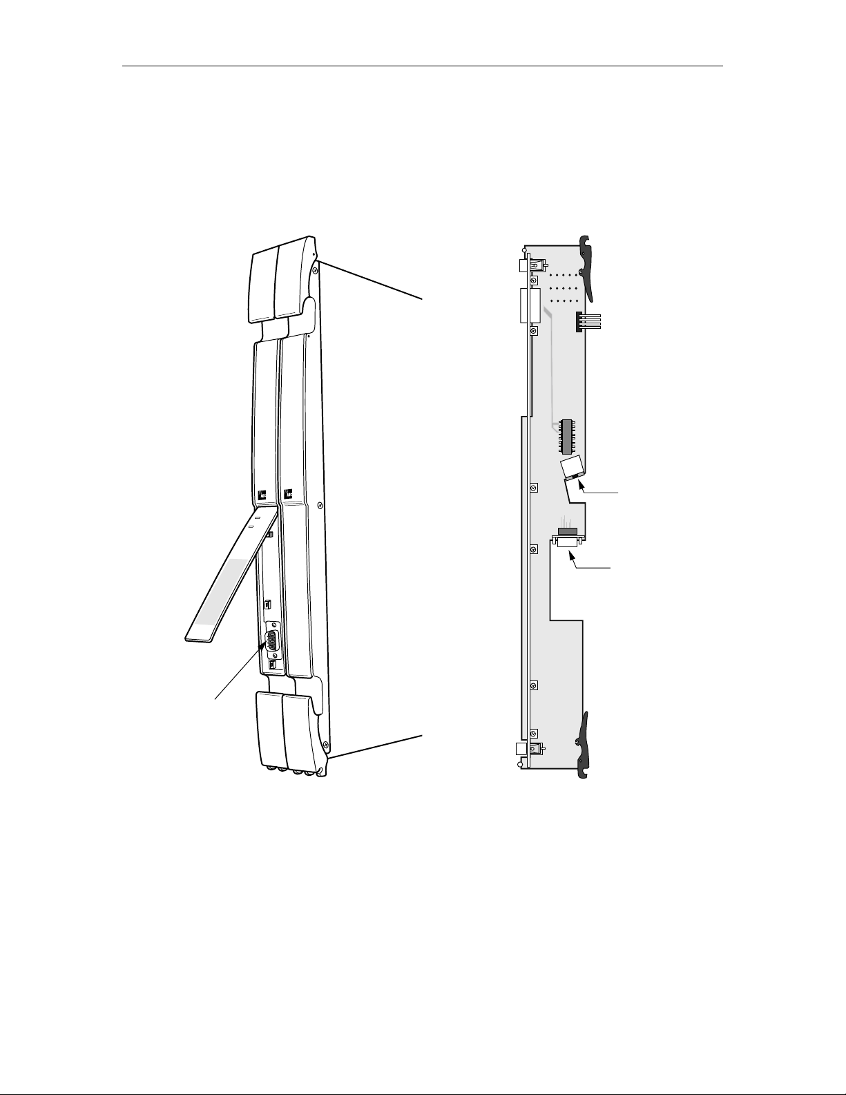
A. NMIC RS232 Interface
3
The NMIC provides an asynchronous RS-232 port for character based access
provided through a DB9 connector located under the front hinged faceplate. This
port is used to load the operating system information and IP addresses at initial
network turn up.
ADCP-70-220 • Issue 1 • September 2000 • Section 1 Introduction
IC
M
N
S
ta
tu
s
Active
C
ra
ft
A
c
c
e
s
s
E
n
ab
le
G
M
S
C
ra
ft
R
e
s
e
t
JA7
P5
P1
A
GND
E11
B
GND
U2
J6
RJ45 ETHERNET
CONNECTION
J2
9 PIN D-SUB EXTERNAL
EQUIPMENT PORT
RS232 PORT
117
J1
Figure 1-2. NMIC Craft Port Identification Figure 1-3. NMIC EIM Port Identifications
B. NMIC EIM RJ45 Ethernet Interface
An external Network Management System (NMS) and/or X-Terminal connection is
provided through an RJ45 10 Base-T Ethernet connection on either NMIC
Electrical Interface Module (NMIC EIM) in slot 2 or 4 at the rear of the shelf.
Refer to Figure 1-3. This connection is available only in the Gateway Network
Element (GNE) located at a Central Office or controlled environment (0-50° C)
location. It provides access to the GUI software screens for all management
© 2000, ADC Telecommunications, Inc.
10490-A
Page 1-3
Page 21

1152700• Issue 1 • February 2001 • Section 1 Introduction
functions, or SNMP access for Sets, Gets, Traps etc. Up to five GUI sessions may
be launched at a time. An X-Terminal may remain active while the GUI is launched
on another terminal. A user establishes a Telnet session to the NMIC to launch the
GUI. The NMIC can maintain the Telnet session after the GUI is exited, or
maintain the GUI functionality after the user terminates the Telnet session, but
once both the Telnet session is terminated and the GUI is exited, the Telnet session
must be re-established.
NMICs support 1:1 protection and provide independent Ethernet connections. Each
NMIC has a unique IP address and a shared IP address, requiring the administrator
to provision each of them on the X-Terminal. If the administrator cannot connect
using the shared IP address (NMICs are unobtainable or a no response message is
generated from a remote Telnet session connection attempt), the administrator can
reattempt the Telnet session utilizing either the working or the protection NMIC IP
addresses.
C. NMIC Serial Equipment Port
A serial port is provided on the NMIC EIM that can be used for modem access or
other types of serial equipment. This port will provide the same system access as
the Ethernet port. It has jumpers that enable the user to strap the port for DTE or
DCE depending on the serial device connected to it.
3. CELLWORX STN SYSTEM SOFTWARE
A. NMIC Graphical User Interface (GUI)
The Cellworx NMIC GUI interface provides a simple, consistent means of
interaction through menu, mouse, and keyboard driven software configuration
options. It is an executable program residing on the NMIC that a user gains access
to through an X-Terminal window from the shell command prompt. The GUI
retrieves data for the user initiated events via SNMP to the Application Core or by
accessing the information stored on its hard disk.
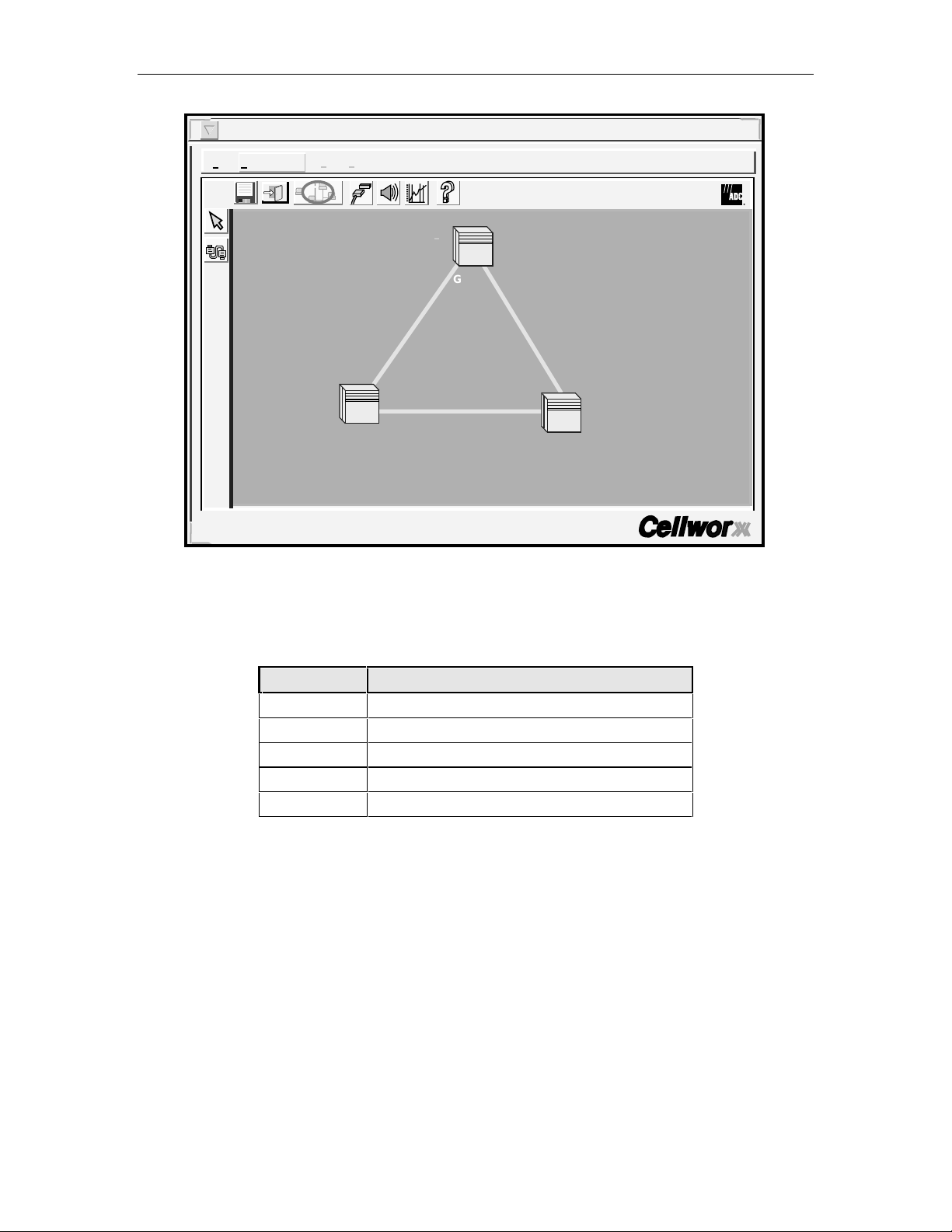
Once connected to the NMIC and logged on to the network, a full network view
encompassing each node in the network is displayed on the screen. An example is
shown in Figure 1-4. An arrangement of icons representing Cellworx STN nodes
reflect the network configuration (if configured) and are color-coded indicating the
current alarm state of each node. Table 1-1 describes the color codes of the icons.
The NE containing the NMICs is referred to as the Gateway Network Element
(GNE) and can be determined at a glance from the yellow text underneath it. All
other nodes will have white text.
The fiber connections shown between the nodes will appear green if there are no
fiber fragment failures. They will turn orange in the event of a fiber fragment
failure indicating a major alarm condition on the link between nodes.
Page 1-4
© 2000, ADC Telecommunications, Inc.
Page 22
ADCP-70-220 • Issue 1 • September 2000 • Section 1 Introduction
Cellworx Vision: Subnetwork Management System
File Configuration Fault Performance Help
i
GNE-1
NE-2
Cellworx User: root
Local Time: 21:35 GMT Time: 21:35
NE-3
10924-D
Figure 1-4. Network Manager Main Screen
Table 1-1. GUI Cellworx STN Node Icon Color Codes
COLOR INDICATION
Green No existing alarms, normal operation.
Yellow Minor alarms exist at this site.
Orange Major alarms exist at this site.
Red Critical alarms exist at this site.
Blue Cannot communicate with the site.
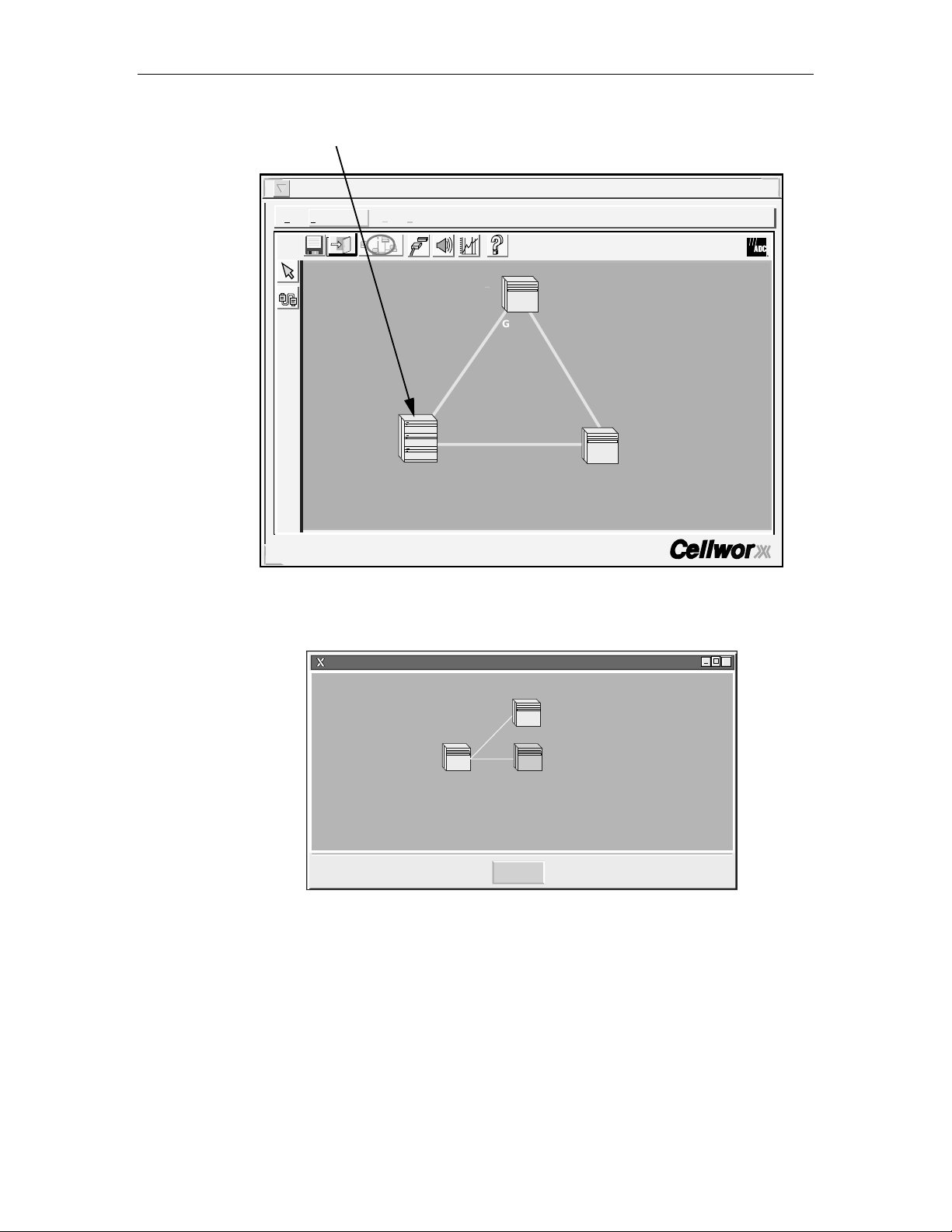
GUI Screen Icon Definitions
Larger icons are used to represent the Cellworx STN shelves that have Secondary
nodes (expansion shelves called STN-EPS) connected to them. These icons are
referred to as Primary nodes and will look the same whether there are 2 or 10 STNEPS nodes connected to them. Refer to Figure 1-5. The Secondary nodes may be
collocated or reside at remote sites. When a user selects a node, it is highlighted by
a white square that surrounds it. By double clicking on one of these nodes with the
left mouse button, a new window is displayed reflecting the interconnecting
relationship between the Primary and Secondary nodes. It is at this point that the
user can determine the number of nodes involved. Refer to Figure 1-6. The Primary
node now appears as a normal size ICON and the ring network interconnections are
not displayed. To return to the ring network view, the operator clicks on the Cancel
button at the bottom of the window.
© 2000, ADC Telecommunications, Inc.
Page 1-5
Page 23
1152700• Issue 1 • February 2001 • Section 1 Introduction
ICON FOR NE-2 INDICATES
THE PRESENCE OF STN-EPS
SHELVES
Cellworx Vision: Subnetwork Management System
File Configuration Fault Performance Help
i
STN
STN
STN
NE-2
GNE-1
NE-3
Cellworx User: root
Local Time: 21:37 GMT Time: 21:37
10926-D
Figure 1-5. Example of Primary Node with Secondary Expans i ons
Cellworx Vision:Physical Layouts for NE-2
EPS-2
NE-2 EPS-1
Cancel
X
10960-B
Figure 1-6. Primary Node Physical Layout to Secondary Nodes
An Auto Discovery feature allows the NMIC to search for and display all nodes
connected in the network during initial system turn-up. Main menu headings are
displayed at the top of the screen (File, Configuration, Fault, Performance) and
when selected will allow the user to perform all higher level functions such as
system administration, establish end to end VP/VC connections, request
performance reports, or display network alarm summaries.
Page 1-6
© 2000, ADC Telecommunications, Inc.
Page 24
ADCP-70-220 • Issue 1 • September 2000 • Section 1 Introduction
To access any node in the network, the administrator selects the direct selection
arrow tool located on the left tool bar, and then double clicks on the NE ICON to
open a shelf level GUI session. To start a craft session with the node, the user
selects the node with a single click, right click to open the pop-up menu, and select
Craft Interface. The administrator is required to enter a valid user name and
password assigned for the node to gain access to the craft menus. The shelf level
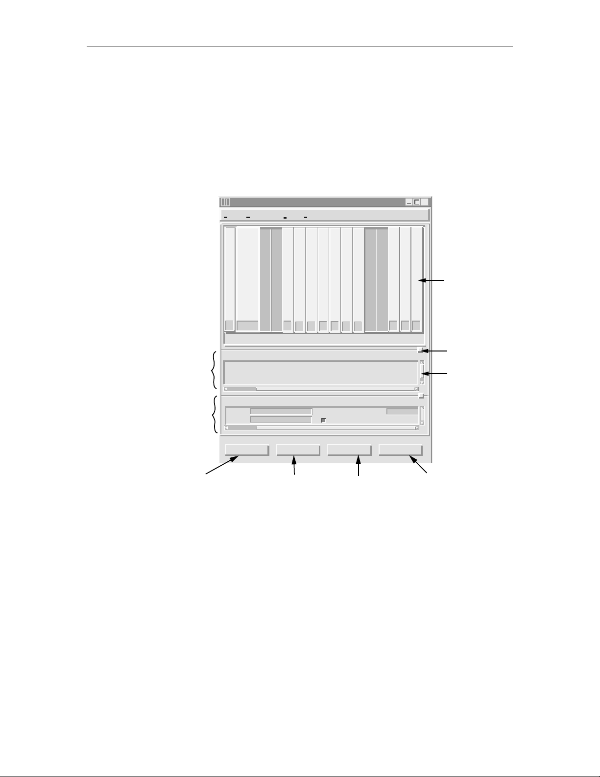
GUI is shown in Figure 1-7 below.
CHASSIS STATUS
CHASSIS
CONFIGURATION
APPLIES CHANGES
AND SENDS TO SHELF
CONTROLLER.
Cellworx Vision: Chassis View, Network Element 2
File Configuration Fault Security
SCN
M
I
C
123456789101112131415161718
Status:
Power Status: normal
Identifier:
Start Time:
Vendor:
Configuration:
2
19:30:47 8/31/1999
ADC-TSG
Cellworx2
Name:
Location:
5th Street
Apply Topology View
T
3
T
M
U
X
T
T
T
3
1
M
M
U
C
u
X
R
l
S
t
E
i
X
P
1
Memory Utilization Threshold:
RETURNS TO GUI MAIN
VIEW WITHOUT CLOSING
CHASSIS LEVEL VIEW.
E
E
T
1
1
3
M
M
u
u
C
l
l
R
t
t
S
i
i
1
1
Alarm Status:
Version:
Current Time:
Up Time:
Suppress Zero Stats
Refresh Close
REP AINTS WINDOW
TO REFLECT ANY
CHANGES.
2
4
8
8
R
i
n
g
minor
1.2.0.35
10:12:09 09/01/1999
1d 19:41:22:00
4
8
8
R
i
n
g
X
SC2
EQUIPPED CARD
REPRESENTATIONS WITH
ALARM INDICATIONS.
CLICK ON BOXES AND DRAG
UP OR DOWN TO WIDEN
STATUS, CONFIGURATION OR
CHASSIS VIEW.
USE SLIDERS TO VIEW
HIDDEN STATUSES OR
SELECTIONS.
CLOSES CHASSIS LEVEL
VIEW AND RETURNS TO
GUI MAIN VIEW.
13454-C
Figure 1-7. Cellworx Shelf Level GUI Screen
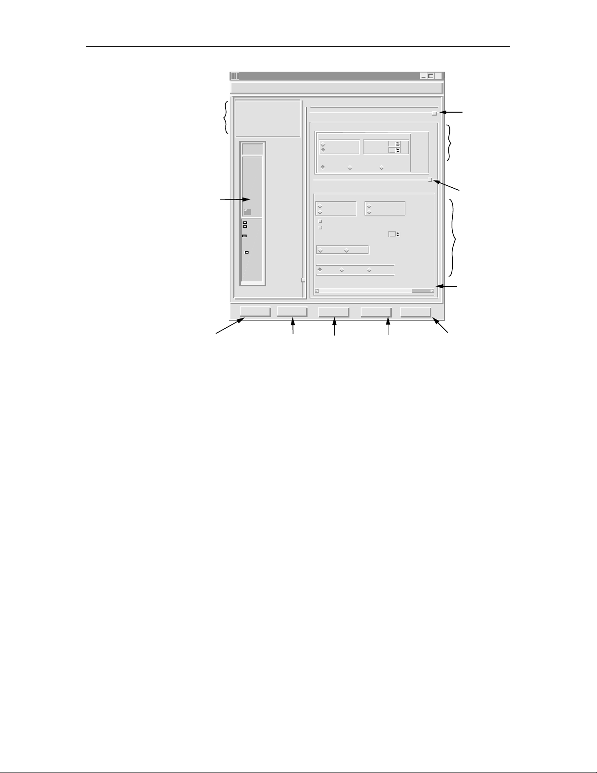
The user can now provision parameters on individual cards in the shelf. To bring up
a card level GUI display, double click on the card displayed in the shelf level view
or put the mouse pointer over the card and hit a right click to open a menu window
for the card and select Open. The Card level view will appear similar to the
example shown in Figure 1-8 below. Some functions available in this view are
described in the figure.
© 2000, ADC Telecommunications, Inc.
Page 1-7
Page 25
1152700• Issue 1 • February 2001 • Section 1 Introduction
NE AND CARD TYPE/
SLOT INFORMATION.
CARD REPRESENTATION
WITH REAL-TIME ALARM
INDICATIONS.
APPLIES CHANGES
AND SENDS TO SHELF
CONTROLLER.
Cellworx Vision: Card View - 622 Ring Interface Card
NE Name: Cellworx1
NE Id: 1
Card: 622 Ring
Slot Number: 17
Port Number: 1
622
Ring
ADC
Status
Status
Active
Active
Protect
Timing
Timing
Port
1
Apply Chassis View
RETURNS TO CHASSIS
VIEW WITHOUT CLOSING
CARD LEVEL VIEW.
Status:
Configuration:
Card Level
Administrative State: Congestion Thresholds:
Ring Selection :
Port Level
Administrative State: Transmit Timing Source:
Locked
Unlocked
Do not use for synchronization
Enable signal degrade
Signal Degrade BER Threshold: 10EMedium Type:
SONET
Loopback towards:
None Terminal
Line Coding:
Line Type:
Diagnostics
PERFORMS TEST
OVER FIBER
LINK.
Locked
Unlocked
Auto Ring 16 Ring 17
SDH
80
Ingress:
Egress:
80
System
Recieved
5
Facility
sonetMediumNRZ
sonetLongSingleMode
Refresh
REPAINTS WINDO W
TO REFLECT ANY
CHANGES.
X
CLICK ON BOX AND DRAG
UP OR DOWN TO WIDEN
STATUS OR CONFIGURATION
VIEWS.
%
%
Close
CARD LEVEL
CONFIGURATION OPTIONS.
CLICK ON BOX AND DRAG UP
OR DOWN TO WIDEN PORT
LEVEL VIEW.
622 MBPS PORT LEVEL
CONFIGURATION OPTIONS.
USE SLIDERS TO VIEW
HIDDEN SELECTIONS.
CLOSES CARD LEVEL
VIEW AND RETURNS TO
SHELF LEVEL VIEW.
13443-B
Figure 1-8. Cellworx Vision Card Level View (622 Ring Interface Car d example)
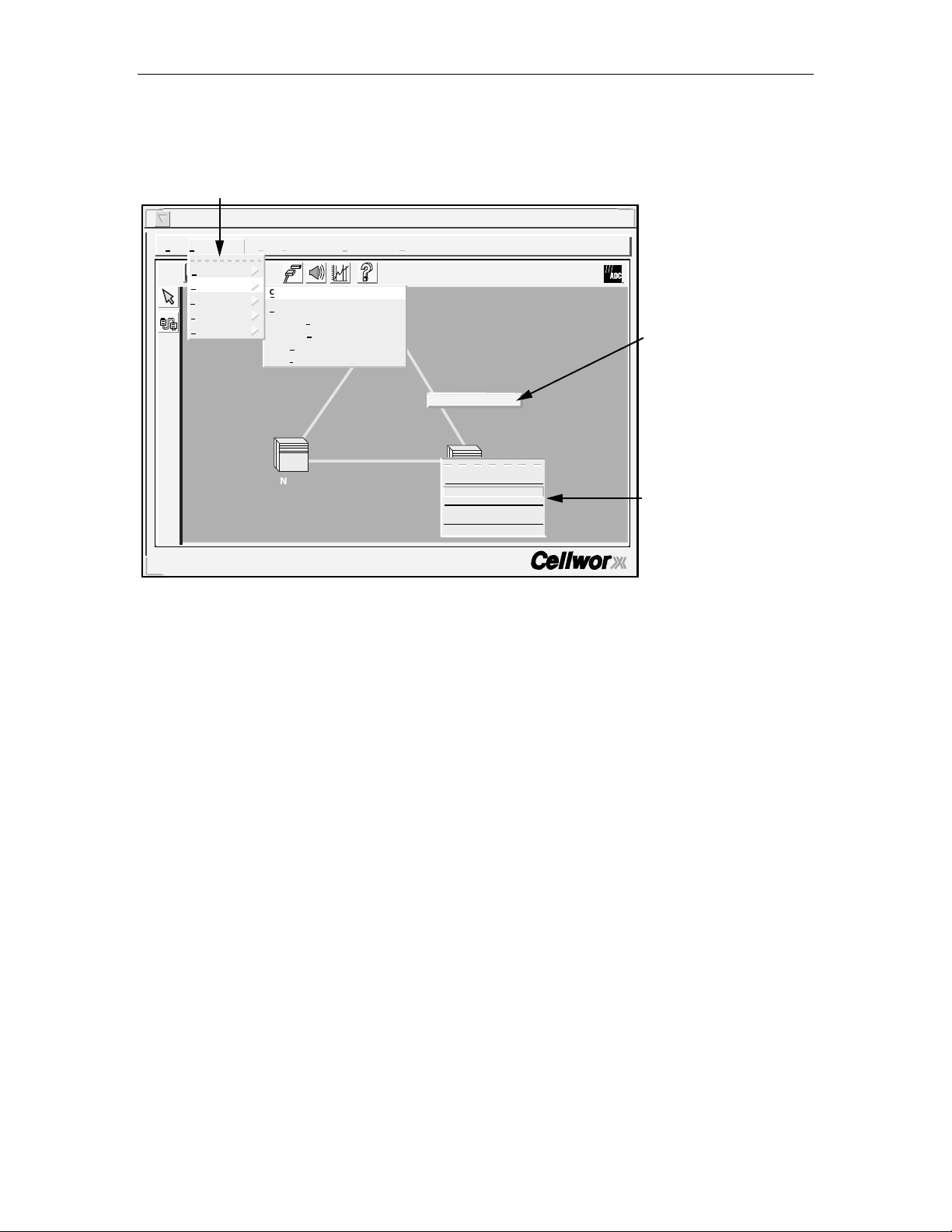
GUI Menu Structure and Utilization
There are three possible methods for performing configuration tasks using the GUI;
1) utilizing the pull down menu trees, 2) mouse controlled popup menus, 3)
keyboard operations. Refer to Figure 1-9 for examples.
• Using the mouse, click the right button over the work area to display the
popup menu and select desired task using the left mouse button. This may
bring up another pop up menu, depending on the task.
• Using the mouse, select a topic on the menu bar above the work area using the
left mouse button. Select a task shown on the pull down menu using the left
mouse button. This may bring up a pop up menu, depending on the task.
• Using the keyboard, select “Alt” plus the underlined letter of a topic shown on
the menu bar above the work area. This opens the pull down menu from the
menu bar. Using the arrow keys on the keyboard, step up or down to the
desired task and hit enter, or return, or right arrow. Other pop up menus may
be generated depending on the task.
Page 1-8
© 2000, ADC Telecommunications, Inc.
Page 26
ADCP-70-220 • Issue 1 • September 2000 • Section 1 Introduction
SELECTING THE TOPIC USING THE LEFT MOUSE BUTTON,
OR ALT PLUS THE UNDERLINED LETTER, OPENS THE PULL
DOWN MENU LIST. SELECT OPTION USING LEFT MOUSE
BUTTON OR DOWN ARROW FOLLOWED BY A RIGHT ARROW.
Cellworx Vision Subnetwork Management System
File Configuration Fault Performance Accounting Security Help
Time and Date
Connection
Topology
Software
NMIC Platform
Cellworx User: root
Local Time: 23:30 GMT Time: 23:30
i
Create...
View ...
Configure Traffic Contract ...
Configure Service Provider Profile ...
View Ring Resource Usage ...
View Fiber Bandwidth Usage ...
NE-2
GNE-1
Fiber Bandwidth Usage...
About...
Craft Interface...
NE-3
Create Connection...
View Connection...
Configure Alarm Threshold...
Configure Software...
Reflash Boot Image
Figure 1-9. Cellworx STN GUI Di splay (sample)
CLICK THE RIGHT MOUSE
OVER THE FIBER TO
OPEN POP UP WINDOW.
SELECTING A NODE WITH LEFT
MOUSE BUTTON AND THEN
HITTING RIGHT MOUSE BUTTON
OPENS THE NE POP UP MENU.
10921-F
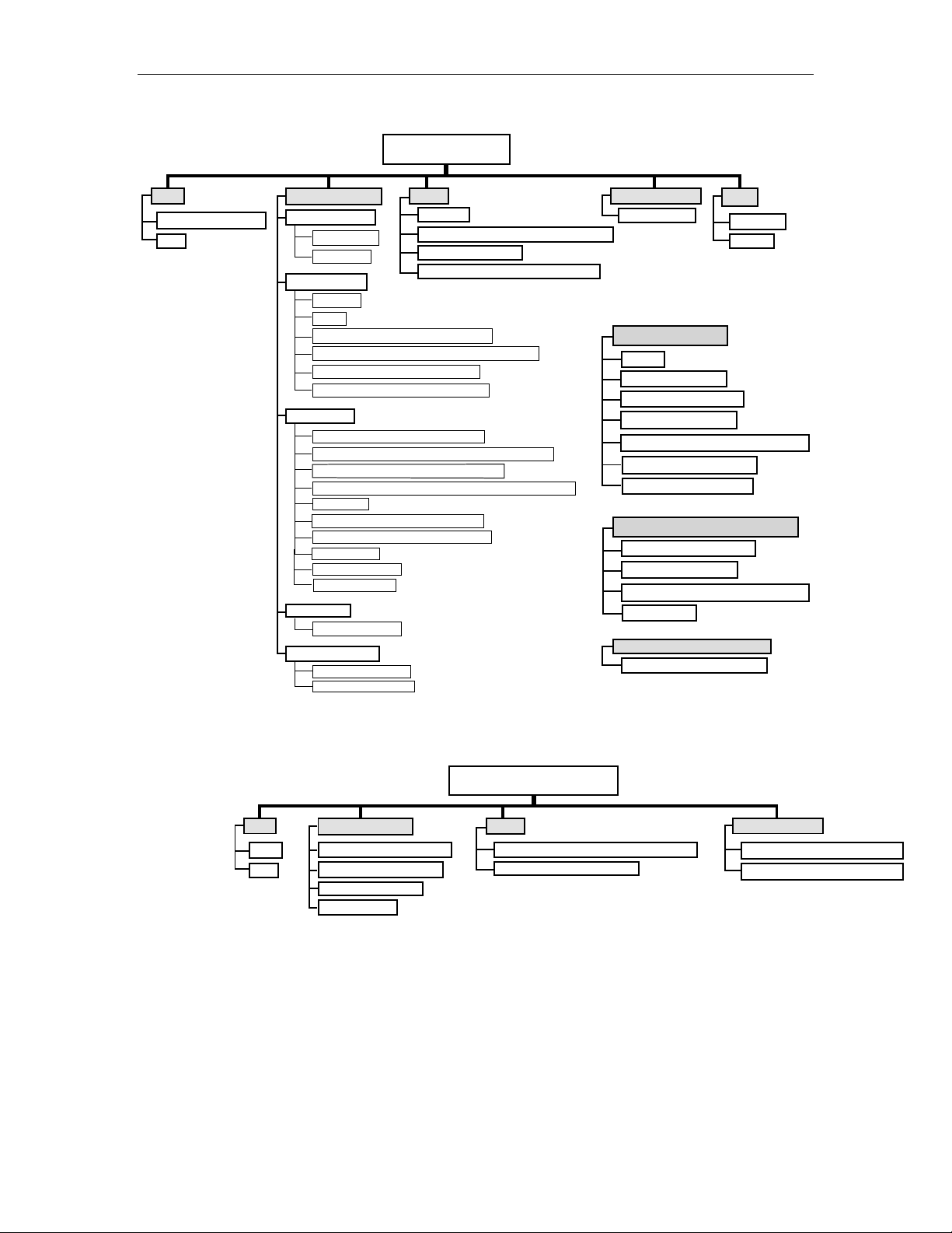
The pull down menus and pop-up window menu structures for the main GUI screen
are shown in the menu tree in Figure 1-10. The pull down menus for the Shelf level
GUI is shown in Figure 1-11.
© 2000, ADC Telecommunications, Inc.
Page 1-9
Page 27
1152700• Issue 1 • February 2001 • Section 1 Introduction
GUI MAIN SCREEN
FILE
SAVE ICON LAYOUT
EXIT
CONFIGURATION
TIME AND DATE
ABSOLUTE
RELATIVE
CONNECTION
CREATE
VIEW
CONFIGURE TRAFFIC CONTRACT
CONFIGURE SERVICE PROVIDER PROFILE
VIEW RING RESOURCE USAGE
VIEW FIBER BANDWIDTH USAGE
TOPOLOGY
ADD RING NETWORK ELEMENT
ADD EXPANSION SHELF NETWORK ELEMENT
REMOVE RING NETWORK ELEMENT
REMOVE EXPANSION SHELF NETWORK ELEMENT
REFRESH
FORCE NETWORK DISCOVERY
REVERT TO SAVED ICON LAYOUT
RING AUDIT
RING UPGRADE
TURN-UP RING
SOFTWARE
CONFIGURE NE
NMIC PLATFORM
ADMINISTRATION
FILE REPLICATION
FAULT
ALARMS
CONFIGURE NE ALARM THRESHOLD
NMIC PROTECTION
NMIC PROTECTION RESTORATION
PERFORMANCE
MONITORING
NE POP-UP WINDOW
ABOUT
CRAFT INTERFACE
CREATE CONNECTION
VIEW CONNECTIONS
CONFIGURE ALARM THRESHOLDS
CONFIGURE SOFTWARE
REFLASH BOOT IMAGE
PRIMARY NODE POP-UP WINDOW
CREATE A CONNECTION
VIEW CONNECTIONS
CONFIGURE ALARM THRESHOLDS
REFRESH NE
FIBER LINK POP-UP WINDOW
FIBER BANDWIDTH USAGE
HELP
CONTACT
ABOUT
10922-F
Figure 1-10. Cellworx Vision Pull Down Menus and Pop-up Window Trees
FILE
SAVE
EXIT
CONFIGURATION
HARDWARE INVENTORY
PROTECTION GROUPS
TIMING RESOURCE
RESET SLOTS
Figure 1-11. Cellworx Shelf Level GUI Pull Down Menu Structure
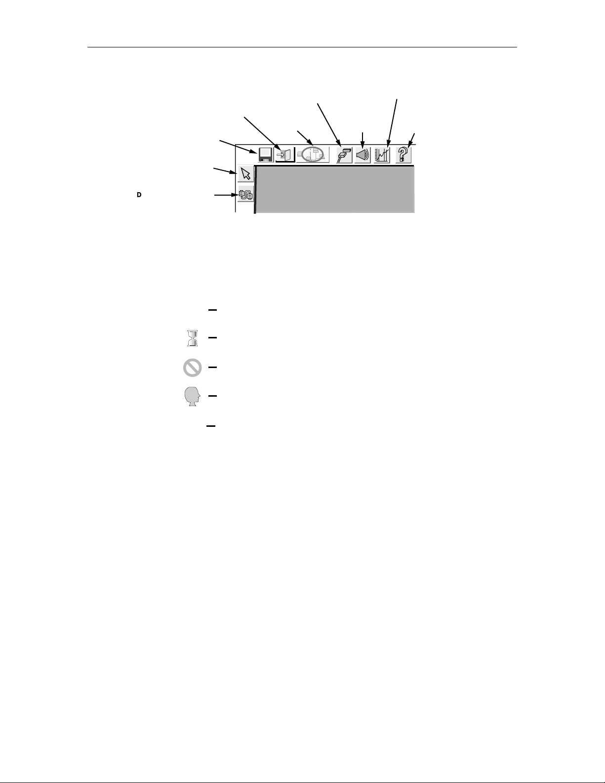
Just outside the workspace the tool bar displays icons placed horizontally and
vertically. These Icons provide shortcuts to common tasks for the advanced user.
The functions of these icons are described in Figure 1-12.
Page 1-10
© 2000, ADC Telecommunications, Inc.
SHELF LEVEL GUI MENU
FAULT
CONFIGURE HOUSEKEEPING ALARMS
EXECUTE ALARM CUT-OFF
SECURITY
CRAFT USER CONGIURATION
CRAFT MENU CONGIURATION
13571-A
Page 28
ADCP-70-220 • Issue 1 • September 2000 • Section 1 Introduction
PERFORMANCE
ALARM
HISTORY
DATA
MANAGEMENT
DATA
CELLW ORX VISION
HELP SCREEN
SAVE NE ICON LAYOUT
VIEW ALL SUBNETWORK
CONNECTIONS...
EXIT
REFRESH
TOPOLOGY
i
SELECT MODE TOOL
DRAG AND DROP TO
CREATE A CONNECTION
Figure 1-12. GUI Tool Bar Icon Definitions
While performing tasks, a user may encounter message windows, confirmation
windows, and informational windows. Each window can be distinguished by the
icon to the left as shown in Figure 1-13.
INFORMATIONAL WINDOW INDICATING A TASK HAS BEEN COMPLETED,
i
i
OR INSTRUCTING THE USER TO ENTER INFORMATION. GENERALLY
REQUIRES THE USER TO SELECT "OK".
10940-B
HOURGLASS INDICATES A TASK IS IN PROGRESS AFTER CHANGES
TO THE SYSTEM HAVE BEEN SENT BY THE USER.
ERROR MESSAGE INDICATES THAT THE TASK COULD NOT BE COMPLETED
DUE TO LACK OF INFORMATION, HARDWARE, COMMUNICATION, ETC.
QUESTION ICON INDICATES THAT THE USER MUST THINK AND MAKE
?
!
A SELECTION BEFORE CONTINUING.
WARNING MESSAGE INDICATING A POTENTIAL PROBLEM, GENERALLY
REQUIRES THE USER TO SELECT "OK".
!
10939-C
Figure 1-13. Cellworx Vision Window Icon Definitions
© 2000, ADC Telecommunications, Inc.
Page 1-11
Page 29

1152700• Issue 1 • February 2001 • Section 1 Introduction
X-Terminal Keyboard Functions
All of the functions that can be performed through pop up menus using the mouse
can also be performed via the menu bar at the top of the screen. The menu bar
provides pull down menus under these options: File, Configuration, Fault, and
Performance.
The keyboard is used to select the menu bar items, navigate and select sub menu
items, bring up the configuration or query screens, and when necessary, to enter
alphanumeric information into the system. Keyboard operations for the GUI also
make use of the arrow keys, enter or return key, tab key, space bar, and control key.
The user must hit the Alt key along with the underlined letter of the menu item
desired (ex. Alt + F selects the File menu tree).
By entering the tab key, the operator moves the highlighted or underlined selection
to the next menu item (ex. File to Configuration.) Hitting the enter or return key
opens the menu item. The operator may now use the arrow keys to step down or up
to the desired item selection. The right arrow will bring up a sub menu if one exists,
indicated by the arrow pointing to the right beside the text in the menu list.
Manipulating the GUI Network Layout on an X-Terminal Screen
The user may redraw the layout of the network that is displayed by the GUI. This
may be performed to set a group of nodes that are co-located apart from others, to
place the nodes in a city or state map layout, or just to make use of more room on
the screen itself. By selecting a node using the select mode tool and a single click
and hold of the left mouse button, the operator can drag it to any area of the screen
and then release the mouse button. The node is now planted in its new location on
the screen and all of the connections stay intact (the operator cannot change the
physical location or inter-connections between the nodes by moving an icon into
another area of the software screen).
Once the user has redrawn the GUI screen layout, the new screen configuration
should be saved. This can be done through the menu bar under File: Save Icon
Layout, or by single clicking on the floppy disk icon on the tool bar above the work
area.
Page 1-12
© 2000, ADC Telecommunications, Inc.
Page 30
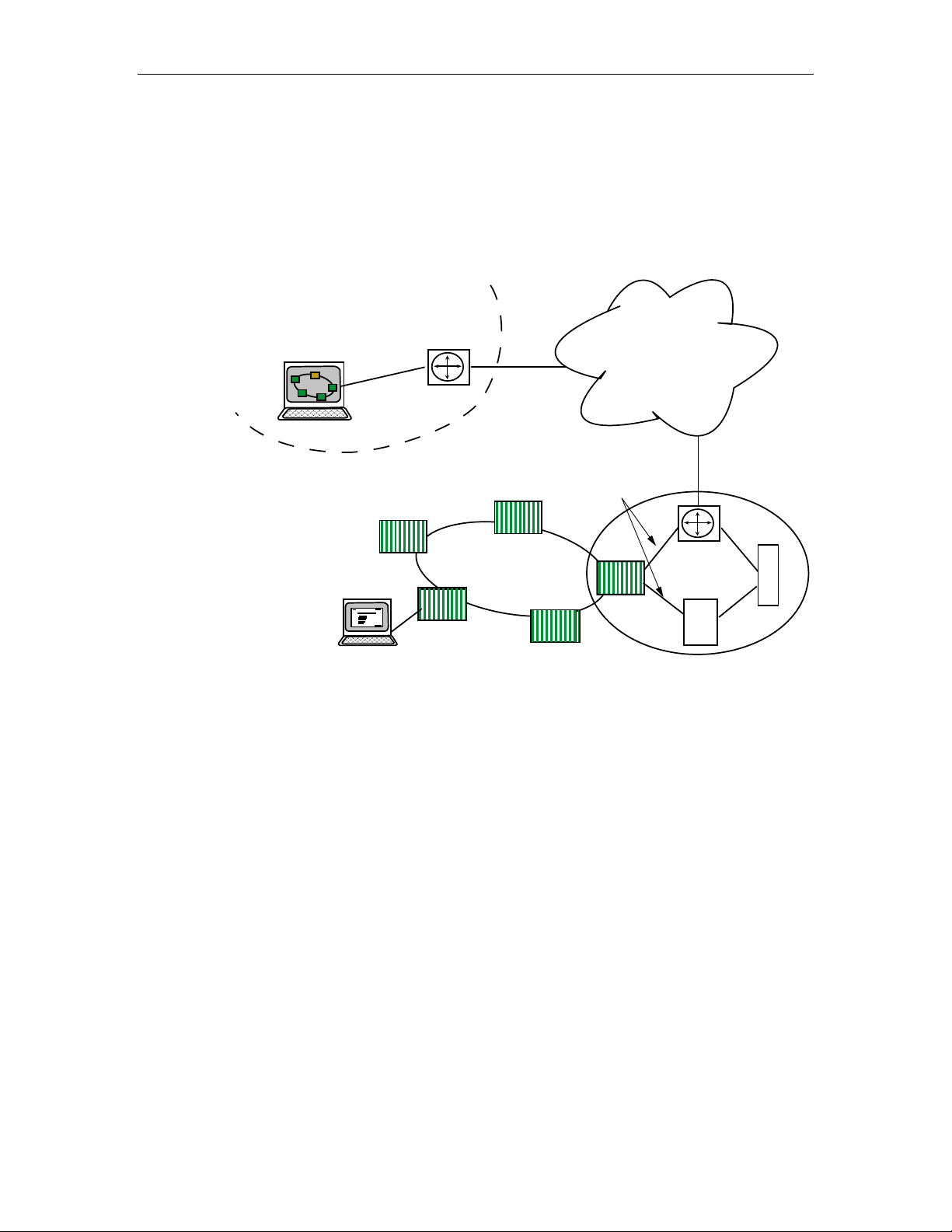
4. REMOTE MANAGEMENT CAPABILITIES
The X-Terminal used for operations and maintenance of the Cellworx STN
network can be linked through existing customer Ethernet networks using TCP/IP
over any transport layer (e.g. Frame Relay, ATM, Private Line, etc.) Refer to
Figure 1-14 for an example.
NETWORK SURVEILLANCE CENTER
X TERMINAL
ROUTER
ADCP-70-220 • Issue 1 • September 2000 • Section 1 Introduction
EXISTING DEDICATED
NETWORK FOR
MANAGEMENT TRAFFIC
TCP/IP
10 BASE T
ETHERNET
ROUTER
FR
CENTRAL OFFICE
B
S
S
10504-B
LOCAL CRAFT USER
CELLWORX
OC12C RING
GNE
Figure 1-14. Remote X- Terminal Operations
The network operator can use any workstation with a standard X-Windows
platform or a PC with X-Terminal emulation to remotely access the network,
launch the GUI, and monitor or troubleshoot the Cellworx STN ring network. The
operator can remotely connect to a node via Telnet session through the NMIC, and
use craft menus to retrieve alarm and performance information. These functions are
performed utilizing IP addresses set up for each node at turn up.
Messaging between remote nodes and the GNE NMIC is performed by targeting
the NE’s IP address. Many existing network components (BSS, ATM Switches,
frame relay switches, and routers) can also be pulled up on the same X-Terminal
for maintenance and troubleshooting capabilities.
© 2000, ADC Telecommunications, Inc.
Page 1-13
Page 31

1152700• Issue 1 • February 2001 • Section 1 Introduction
A. Real-time Alarm and Trap Screens
The Cellworx NMIC provides real time alarm monitoring capabilities to an
External Management System (EMS) via SNMP traps through an Ethernet port on
the NMIC EIM. This scheme supports remote retrieval of NMIC collected data for
user manipulation and report creation via ftp using four simple file types. These
files are comma, space, or tab delimited and cover the following categories of
collected data: Alarm history, Accounting, PM data, and Network Data Collection.
The NMIC serves as an ATM domain operations interface provided on a Cellworx
STN shelf configured as a Gateway Network Element (GNE), generally located in
the CO or manned site. The NMIC can process 1.6K TFTP (Trivial FTP)/FTP
packets as well as 0.8Mbytes of data per second, serving as an FTP server for each
of the NE Shelf Controllers (SCs). The alarm history from each of the NE SC traps
is stored up to 24 hours for future queries. The NMIC sends an SNMP request to
the destined NE based on legitimate SNMP requests received from the EMS, and
discards all IP packets that are different from its IP address.
The SNMP MIB for ring management is ATM Forum network view M4 based. The
NE processes up to ten SNMP traps per second also.
GR-1248, [213] is supported. The NMIC supports the user identification,
authentication, system access control, resource access control, security log, and
security administration requirements as stated in GR-1248 [213]. The administrator
can configure the option of allowing the user to only perform SNMP get requests
and receive SNMP traps.
Page 1-14
© 2000, ADC Telecommunications, Inc.
Page 32

1152700• Issue 1 • February 2001 • Section 2 Operation and Maintenance
SECTION 2
OPERATION AND MAINTENANCE TOP
Content Page
1. GENERAL ................................................................................................................................................. 2-1
2. USING A TOP DOCUMENT................................................................................................................................ 2-1
ALPHABETICAL TASK I NDEX LIST ......................................................................................................................... 2-3
INSTALLATION TASK INDEX LIST.....................................................................................................................IXL-001
1 GENERAL
This section provides operation and maintenance procedures for the Cellworx Service Transport Node
(STN) for the system administrator/operator.
Operation and maintenance includes but is not limited to the following tasks:
• Performing end to end signal tests to verify system operation.
• Adding modules to an in-service chassis.
• Configuring the modules for operation (S/W configuration and download).
• Configuring the VP/VC traffic connections for operation.
• Troubleshooting alarm conditions.
• Using the GUI interface to check network and node statuses.
• Performing card/traffic level switching for maintenance, troubleshooting, or testing
purposes.
2 USING A TOP DOCUMENT
The procedures in this section are written in the Task Oriented Process (TOP) format. The TOP method of
presenting information provides step by step instructions for the successful completion of the indicated
task. To find the instructions for performing enclosure installation, module installation and initial turn up,
and installation troubleshooting tasks, refer to Figure 2-1 for the flow chart of a TOPS document or
proceed as follows:
1. Find the task to be performed in the Indexed Task List (IXL-001), or the Alphabetical
Task Index List.
2. Locate the specified director level, detail level, or trouble clearing procedure. All
procedures are in numerical order, regardless of type. The TOP procedures in this
manual are of the following four types:
a) Non-Trouble Clearing Procedure (NTP) − A director level procedure that lists
normal work items to be performed that are not trouble clearing procedures.
b) Trouble Analysis Procedure (TAP) − A director level procedure that provides step
by step instructions to locate and fix problems.
c) Detailed Level Procedure (DLP) − Detailed step by step instructions or procedures.
© 2000 ADC Telecommunications, Inc.
Page 2-1
Page 33

1152700• Issue 1 • February 2001 Section 2 Operation and Maintenance
d) Trouble Analysis Data (TAD) − A trouble clearing aid containing non-procedural
data.
3. Perform all the items in the director level procedure (NTP ‘or TAP) in the order listed
unless sent to another director level procedure. When a director level procedure is
finished, the task is completed. When more detailed information is required, the reader
will be sent to a DLP. A DLP may also direct the reader to another DLP.
Note: When a DLP is complete, return to the procedure that preceded the DLP.
Note: When sent from one DLP to another DLP, in most instances it will not be necessary to go
back to the first DLP after competing the second.
4. In some procedures, it will be necessary to verify that certain responses have occurred. If the
expected response is not observed, refer to the TAP. If additional data is required such as a
schematic diagram, line drawing, tabulated data, maintenance philosophy, or trouble clearing
strategy, the reader will be sent to a TAD.
Find the task to be performed in either the Indexed T ask List,
or the Alphabetical Task List. These will refer to NTP, DLP,
or T AP procedures.
NTP?
Perform each task
listed in order in
an NTP until
completed.
DONE?
Perform each task
listed in order in
an NTP until
completed. In most
cases, will not
return to previous
NTP.
Locate the NTP, DLP, or TAP referred to in the Task Lists.
DLP?
REFERS
TO DLP
REFERS TO
ANOTHER
NTP?
REFERS
TO DLP
DONE? DONE?
Perform detailed
steps listed in a DLP
until completed.
Return to NTP if
applicable.
DONE?
Perform detailed
steps listed in
a DLP until completed.
Return to NTP if
applicable.
REFERS
TO T AP?
REFERS
TO T AP?
REFERS TO
ANOTHER
DLP?
REFERS TO
ANOTHER
DLP?
TAP?
Perform detailed
steps listed in a DLP
until completed,
then return to previous
procedure.
REFERS
TO T AP?
REFERS
TO T AP?
Perform detailed
steps listed in a DLP
until completed,
then return to previous
procedure.
RETURN
TO DLP
Trouble Analysis Procedure,
located at the back of the section,
referenced to by DLPs when
expected responses are not
observed. Perform each step in
order to locate and fix troubles,
then return to DLP if applicable.
Page 2-2
© 2000 ADC Telecommunications, Inc.
Task Completed
Figure 2-1. TOPS Docum ent Flow Chart
10556-C
Page 34

1152700• Issue 1 • February 2001 • Section 2 Operation and Maintenance
Page 1 of 3
ALPHABETICAL TASK INDEX LIST
Find Your Job in the List Below Then Go To
ABOUT NE ............................................................................DLP-721
ADD A CELLWORX STN NODE TO AN IN-SERVICE RING NETWORK .........................................NTP-003
ADD A SECOND NETWORK ELEMENT TO AN IN SERVICE STAND-ALONE TERMINAL NODE
TO CREATE A RING NETWORK .......................................................NTP-004
ADD/DELETE A LEAF ENDPOINT TO/FROM AN EXISTING MULTICAST CONNECTION .............................DLP-791
ADD/DELETE GUI USERS OR CHANGE GUI USER LEVEL SECURITY .........................................DLP-783
ADD EXPANSION SHELF (STN-EPS) ..............................................................DLP-712
ADD A RING NETWORK ELEMENT ...............................................................DLP-737
ADD A SECOND NETWORK ELEMENT .............................................................DLP-738
ADD OR CHANGE AN SNMP TRAP HOST ON THE NMIC .................................................DLP-775
ADDING SERVICES TO A CELLWORX STN NODE......................................................NTP-009
ADMINISTRATIVE TASKS .....................................................................NTP-015
ALARM CUT-OFF ..........................................................................DLP-776
CARD RESET ............................................................................DLP-773
CHANGE CONFIGURATION/TEST AN EXISTING CONNECTION .............................................DLP-723
CONDUCT ACCEPTANCE TESTS ON CELLWORX STN NODE ..............................................NTP-011
CONFIGURE CARD PROTECTION GROUPS..........................................................DLP-765
CONFIGURE NE ALARM THRESHOLD .............................................................DLP-717
CONFIGURE OR DELETE A TRAFFIC CONTRACT......................................................DLP-709
CONFIGURE SERVICE PROVIDER PROFILE .........................................................DLP-714
CONNECT FIBERS TO OPTICAL CARDS ...........................................................DLP-701
CONNECT NMS OR X-TERMINAL TO THE NMIC EIM SNMP/GUI PORT .......................................DLP-704
CONNECT VT100 TO NMIC RS-232 PORT AND VERIFY NMIC IP ADDRESS ....................................DLP-702
CREATE AN ATM OR CES CONNECTION ...........................................................DLP-708
CREATE A FRAME RELAY CONNECTION ...........................................................DLP-786
CREATE AN ATM BUNDLED VC MULTICASTING CONNECTION. ............................................DLP-790
CREATE AN ATM MULTICAST CONNECTION.........................................................DLP-787
DELETE A CELLWORX STN NODE ...............................................................NTP-010
DELETE A CELLWORX STN NODE ...............................................................DLP-740
DELETE A CELLWORX STN EXPANSION SHELF (EPS) ..................................................DLP-746
DELETE CONNECTIONS ......................................................................DLP-739
DISPLAY NETWORK ALARM SUMMARY ...........................................................DLP-713
DISPLAYING STATUS AND ALARMS..............................................................NTP-007
ENDING A GUI SESSION FOLLOWING AN ABNORMAL SESSION ENDING .....................................DLP-778
FINDING AND CHANGING NMIC IP ADDRESS........................................................DLP-774
FORCE NETWORK DISCOVERY .................................................................DLP-719
FTP DATABASE FILES OFF OF NMIC..............................................................DLP-782
HARDWARE INVENTORY .....................................................................DLP-770
(continued)
© 2000 ADC Telecommunications, Inc.
Page 2-3
Page 35

1152700• Issue 1 • February 2001 Section 2 Operation and Maintenance
Page 2 of 3
ALPHABETICAL TASK INDEX LIST, CONTINUED
Find Your Job in the List Below, continued Then Go To
HELP ............................................................................DLP-735
INITIATE A PROTECTION SWITCH ...............................................................DLP-771
LAUNCH THE GRAPHICAL USER INTERFACE (GUI) ....................................................DLP-705
LOG OFF OF CELLWORX STN GRAPHICAL USER INTERFACE .............................................DLP-711
LOG ON TO REMOTE NODE CRAFT SESSION VIA TELNET FROM GUI ........................................DLP-703
LOOPBACK TEST...........................................................................DLP-772
MONITORING THE NETWORK ..................................................................NTP-014
NMIC PROTECTION .........................................................................DLP-724
NMIC PROTECTION RESTORATION ..............................................................DLP-725
NMIC SYSTEM FILE REPLICATION...............................................................DLP-722
PERFORM DIAGNOSTICS ON OPTICAL CARDS .......................................................DLP-766
PERFORM DISCOVERY ON A NEW CELLWORX STN RING NETWORK .......................................DLP-706
PERFORM ROUTINE AND NON-ROUTINE MAINTENANCE ................................................NTP-012
PHASE 3.0 TO 3.1 SOFTWARE UPGRADE PROCE DURE .................................................DLP-795
PROVISION ATM VP AND VC CONNECTIONS ........................................................NTP-013
PROVISIONING NODE PARAMETERS .............................................................NTP-006
REFLASH BOOT IMAGE ......................................................................DLP-744
REFRESH TOPOLOGY .......................................................................DLP-718
REMOVE AND/OR REPLACE CELLWORX CARDS......................................................DLP-777
REMOVING A NMIC CARD FROM THE SHELF ........................................................DLP-781
RETRIEVE 155 SM/MM CRS CARD STATUS.........................................................DLP-760
RETRIEVE 622 SM CRS CARD STATUS ............................................................DLP-796
RETRIEVE 155 RING INTERFACE CARD STATUS......................................................DLP-763
RETRIEVE 622 RING INTERFACE CARD STATUS......................................................DLP-759
RETRIEVE 2488 RING INTERFACE CARD STATUS.....................................................DLP-779
RETRIEVE COMPRESSED LOGS FROM THE NMIC VIA F TP ...............................................DLP-742
RETRIEVE FE1 FRS CARD STATUS...............................................................DLP-789
RETRIEVE FT1 FRS CARD STATUS...............................................................DLP-788
RETRIEVE LOGS FROM THE NMIC VIA FTP .........................................................DLP-741
RETRIEVE NETWORK DATA COLLECTION (NDC) STATISTICS .............................................DLP-730
RETRIEVE PERFORMANCE MONITORING STATISTICS VIA NMIC GUI ........................................NTP-008
RETRIEVE SC CARD STATUS...................................................................DLP-757
RETRIEVE T1 MULTI 1 CARD STATUS.............................................................DLP-764
RETRIEVE T3 CES CARD STATUS. ...............................................................DLP-793
RETRIEVE T3 CRS CARD STAT US ...............................................................DLP-761
RETRIEVE T3 TMUX MULTI 1 CARD STATUS ........................................................DLP-762
REVERT TO SAVED ICON LAYOUT ...............................................................DLP-736
RING UPGRADE PROCEDURE ..................................................................DLP-731
(continued)
Page 2-4
© 2000 ADC Telecommunications, Inc.
Page 36

1152700• Issue 1 • February 2001 • Section 2 Operation and Maintenance
ALPHABETICAL TASK INDEX LIST, CONTINUED
Find Your Job in the List Below, continued Then Go To
SET 622 SM CRS CARD CONFIGURATION ..........................................................DLP-797
SET 155 SM/MM CRS CARD CONFIGURATION .......................................................DLP-752
SET 155 RING INTERFACE CARD CONFIGURATION....................................................DLP-758
SET 622 RING INTERFACE CARD CONFIGURATION ...................................................DLP-751
SET 2488 RING INTERFACE CARD CONFIGURATION...................................................DLP-756
SET CRAFT MENU CONFIGURATION..............................................................DLP-769
SET CRAFT USER CONFIGURATION ..............................................................DLP-768
SET E1 MULTI 1 CARD CONFIGURATION...........................................................DLP-747
SET FE1 FRS CARD CONFIGURATION.............................................................DLP-784
SET FT1 FRS CARD CONFIGURATION.............................................................DLP-785
SET / RETRIEVE OPTICAL PORT PE RFORMANCE MONITORING STATISTICS ...................................DLP-726
SET / RETRIEVE T1/E1 MULTI 1 PERFORMANCE MONITORING STATISTICS ...................................DLP-729
SET / RETRIEVE FT1 FRS PERFORMANCE MONITORING STATISTICS........................................DLP-732
SET / RETRIEVE FE1 FRS PERFORMANCE MONITORING STATISTICS........................................DLP-733
SET / RETRIEVE T3 CES PORT PERFORMANCE MONITORING STATISTICS. ....................................DLP-794
SET / RETRIEVE T3 CRS PORT PERFORMANCE MONITORING STATISTICS ....................................DLP-728
SET / RETRIEVE T3 TMUX PERFORMANCE MONITORING STATISTICS .......................................DLP-727
SET SC CARD CONFIGURATION (IP ADDRESS, CRAFT INTER FACE).........................................DLP-748
SET SHELF HOUSEKEEPING ALARM CONFIGURATION..................................................DLP-750
SET SHELF TIMING RESOURCE.................................................................DLP-749
SET SYSTEM IDENTIFIER.....................................................................DLP-767
SET T1 MULTI 1 CARD CONFIGURATION...........................................................DLP-755
SET T3 CES CARD CONFIGURATION. .............................................................DLP-792
SET T3 CRS CARD CONFIGURATION .............................................................DLP-753
SET T3 TMUX MULTI 1 AND TMUX EXP CARD CONFIGURATION ...........................................DLP-754
SOFTWARE FALLBACK FROM 3.1 TO 3.0 ..........................................................DLP-798
SOFTWARE SELECTION .....................................................................DLP-720
SYSTEM DATABASE ACCESS...................................................................DLP-745
TIME AND DATE ...........................................................................DLP-707
TROUBLE ANALYSIS PROCEDURE ............................................................... TAP-100
TURN UP A NEW CELLWORX STN RING NETWORK ...................................................NTP-002
TURN UP (PROVISION) CELLWORX STN EXPANSION SHELVES............................................NTP-005
VIEW CONNECTIONS ........................................................................DLP-710
VIEW FIBER BANDWIDTH USAGE ...............................................................DLP-716
VIEW RING RESOURCE USAGE .................................................................DLP-715
Page 3 of 3
© 2000 ADC Telecommunications, Inc.
Page 2-5
Page 37

ADCP-70-220 •Issue 1 • November 2000 • Section 2 Operation and Maintenance
IXL-001
Page 1 of 1
INDEXED TASK LIST
Find Your Job in the List Below Then Go To
TURN UP A NEW CELLWORX STN RI NG NETWORK .......................................................................................NTP-002
ADD A CELLWORX STN NODE TO AN IN-S ERVICE RING NETWORK.............................................................NTP-003
ADD A SECOND NETWORK ELEMENT T O AN IN-SERVICE STAND-ALONE TERMI NAL
TO CREATE A RING NETWORK ...................................................................................................................NTP-004
TURN UP (PROVISION) CELL WORX STN EXPANSION SHELVES....................................................................NTP-005
PROVISION NODE PARAME T ERS......................................................................................................................NTP-006
DISPLAYING STATUS AND ALARMS .................................................................................................................NTP-007
RETRIEVE PERFORMANCE MONITORING STATISTICS ...................................................................................NTP-008
ADDING SERVICES TO A CE L L W ORX STN NODE............................................................................................NTP-009
DELETE A CELLWORX STN NODE (RNE OR EPS)............................................................................................NTP-010
CONDUCT ACCEPTANCE TESTS ON CELLWORX STN NODE.........................................................................NTP-011
PERFORM ROUTINE OR NON-ROUTINE M AINTENANCE.................................................................................NTP-012
CREATING CONNECTIONS.................................................................................................................................NTP-013
MONITORING THE NETWORK.............................................................................................................................NTP-014
ADMINISTRATIVE TASKS....................................................................................................................................NTP-015
CELLWORX UPGRADE PROCEDURES .............................................................................................................. NTP-016
© 2000, ADC Telecommunications, Inc.
Page 2-7
Page 38

ADCP-70-220 • Issue 1 • November 2000 • Section 2 Operation and Maintenance
NTP-002
Page 1 of 2
TURN UP A NEW CELLWORX STN RING NETWORK
Summary: This procedure covers initial ring network turn-up. Provisioning of the ring nodes
and interfaces as well as adding STN-EPS shelves to the ring nodes is covered in other NTPs. All
ring nodes should be powered on and fiber continuity established between them, completing the
ring architecture (see Installation Guide) before attempting to perform this procedure. Ring
network turn up is originated at the GNE (Gateway Network Element) containing the NMIC
cards. The NMIC card(s) in the GNE contain the proper Operating System and software from the
factory, which must be initialized and loaded from the hard drive. Once the GNE is initialized,
and the other ring nodes are discovered, the NMIC cards can download the required software
loads to the shelf controllers in the remote ring nodes.
Note: If adding a new node to an existing ring network, go to NTP-003.
Note: If adding a node to an in-service stand alone terminal or Service Access
Multiplexer (SAM) to form a ring, go to NTP-004.
Note: If adding expansion shelves to existing nodes, go to NTP-005.
1. Verify NMICs are inserted.
2. Verify all shelf controllers and AICs are installed and nodes are
powered on. If not powered, perform power on procedures. DLP-700
3. Verify that the GNE node, ring nodes, expansion nodes, and/or
SAM/DSLAM nodes are properly identified by the thumbwheel
switch settings on the SC terminating EIM (TEIM) at the rear of
the shelf in slot 18. Refer to the Phase 3.1 Cellworx Installation
Manual listed in the preface of this document. 1152693
Note: If the ID switches are reset then the SC must be hard reset using the Reset buttons
under the front hinged panel.
4. All RIC cards should have fibers connected with one ring in a
clockwise direction, and the other in a counter-clockwise
direction. If fibers are not installed, install per local practices
and connect to optical cards. DLP-701
5. Obtain the IP address of the NMIC. If the IP address is not set,
connect a VT100 Terminal to the NMIC RS232 port and set the
IP address for the GNE. Call the Customer Service number at
the back of this manual if the address has already been set. DLP-702
6. Connect an Ethernet cable to the NMIC Ethernet port on the
NMIC EIM (Electrical Interface Module) at the rear of the shelf. DLP-704
Note: The NMIC will boot and download slot 1 shelf controllers in each ring NE. The
slot one SC in each node then downloads to each slot 18 SC.
Page 2-8
© 2000, ADC Telecommunications, Inc.
Page 39

ADCP-70-220 •Issue 1 • November 2000 • Section 2 Operation and Maintenance
NTP-002
Page 2 of 2
7. Launch the Cellworx Vision Graphical User Interface (GUI). DLP-705
8. After the GUI boots up, it will prompt the user to synchronize
the database. Choose the active NMIC’s database as the correct
database to synchronize.
9. Perform a discovery for a new Cellworx STN ring network. DLP-706
10. Set the Date and Time on the NMIC. DLP-707
11. Set the System Identifier for each node. DLP-767
12. After all nodes are successfully discovered, configure them
before adding any expansion shelves. Configuration may include
timing configuration, locking ports to remove LOS alarms,
configuring the max VC bits to greater than zero to allow VC
connections for each port, etc. NTP-006
13. Refresh the GUI screen so the nodes will display the new names. DLP-718
14. Perform acceptance tests on the new nodes per local
requirements. NTP-011
15. Add expansion shelves to the ring nodes if equipped. NTP-005
16. Save the NMIC database. DLP-745
Stop! You have completed this procedure.
© 2000, ADC Telecommunications, Inc.
Page 2-9
Page 40

ADCP-70-220 • Issue 1 • November 2000 • Section 2 Operation and Maintenance
NTP-003
Page 1 of 1
ADD A CELLWORX STN NODE TO AN IN-SERVICE RI NG NETWORK
Summary: This procedure describes the steps required to add a new Cellworx STN ring node to
a ring network that has previously been configured and may currently be passing traffic. Due to
the protection operation of the unidirectional path switched ring (UPSR) architecture, adding a
new ring node to an in-service network can be accomplished without affecting traffic or
performance. Before performing this procedure, the new shelves and hardware should be
installed and powered on per the instructions provided in the Cellworx STN Installation Manual
1152693. If adding a second node or multiple nodes to a standalone terminal to form a ring, you
must first perform NTP-004. The procedure for adding a second network element to a standalone terminal or SAM is different from adding a new NE to an established ring network.
1. Launch the Cellworx Vision GUI from the X-Terminal. DLP-705
2. If an abnormal GUI session ending occurred from operator error,
time out, or other unforeseen events, it might be necessary to
free up the GUI and log back in. DLP-778
3. Add the Cellworx STN shelves to the ring. The shelf ID
switches should have been set during installation and recorded
on the label provided inside the front door panel. Follow the
detailed instructions carefully to ensure the traffic on the ring is
not interrupted. DLP-737
4. Configure the node parameters. NTP-006
5. Refresh the network topology (layout) on the GUI screen. DLP-718
6. Perform acceptance tests on the new nodes per local
requirements. NTP-011
7. Add expansion shelves to the new node(s) if equipped. NTP-005
8. Save NMIC database. DLP-745
Stop! You have completed this procedure.
Page 2-10
© 2000, ADC Telecommunications, Inc.
Page 41

ADCP-70-220 •Issue 1 • November 2000 • Section 2 Operation and Maintenance
NTP-004
Page 1 of 1
ADD A SECOND NETWORK ELEMENT TO AN IN-SERVI CE STAND-ALONE
TERMINAL TO CREATE A RING NETWORK
Summary: This procedure describes the steps required to add a new Cellworx STN node to an
in-service, Service Access Multiplexer (SAM) node or stand-alone terminal to create a two node
ring. Only the second node in a network may be added using this procedure. If adding additional
nodes (third, fourth, etc.) to a ring system, perform NTP-003.
1. Verify the new node is powered on. If not, perform power on
procedures at the location. DLP-700
2. Verify the new node has the required RIC cards physically
installed and fibers are connected. Refer to the Cellworx
Installation manual listed in the preface of this document for
card installation or use the fiber procedure to install fibers. DLP-701
3. Launch the Cellworx Vision GUI from the X-Terminal. DLP-705
4. If an abnormal GUI session ending occurred from operator error,
time out, or other unforeseen events, it might be necessary to
free up the GUI and log back in. DLP-778
5. If adding a node to a SAM to form a ring, change the shelf type
(from a 6 to a 1) to a ring node via the thumbwheel switch on
the SC terminating EIM (TEIM). It can be located at the rear of
the shelf in slot 18. Refer to the Phase 3.1 Cellworx Installation
Manual listed in the preface of this document. Otherwise, go to
step 7. 1152693
6. Verify the RICs are installed in the SAM node and then perform
a hard reset on the SCs so they will read the new shelf type. This
will be traffic affecting. DLP-773
5. Add the Cellworx STN shelf to the standalone node. The shelf
IDs of the new node should have been set during installation and
recorded on the label provided on the inside of the front door
panel. DLP-738
6. Configure the node parameters. NTP-006
7. Perform acceptance tests on the new node. NTP-011
8. Add an expansion shelf to the new node if equipped. NTP-005
9. Save the NMIC database. DLP-745
Stop! You have completed this procedure.
© 2000, ADC Telecommunications, Inc.
Page 2-11
Page 42

ADCP-70-220 • Issue 1 • November 2000 • Section 2 Operation and Maintenance
NTP-005
Page 1 of 2
TURN UP (PROVISION) CELLWO RX STN EXPANSION SHELVES
Summary: This procedure describes the steps required to add a Cellworx STN expansion shelf
(STN-EPS) to an in-service ring node or one that has just completed the initial discovery
process.
Note: Applications using the 19-inch chassis will show card slots 1 through 18 but only
card slots 1 through 11 and 16 through 18 are programmable.
Prerequisites to this procedure are:
• Ring node must be in-service and fibers correctly installed to the expansion shelf.
• Shelf ExPansion Interface Cards (SEPICs) cards must be installed and in-service in the
ring node.
• Shelf ExPansion Interface Cards (SEPICs) must be installed in the expansion shelf.
• Expansion shelf must have shelf type set to 03 for expansion NE. This is accomplished
by the thumbwheel switch on SC TEIM in slot 18 at the rear of the shelf and should have
been set during shelf installation procedures. If shelf type is changed, SC card must be
reset using the button under the front hinged faceplate. Refer to the Installation Manual
1152693.
1. Ensure there is not a Level 1 GUI user logged onto the system.
If necessary, force the user session off using the following
procedure: DLP-778
2. Launch the Cellworx Vision GUI from the X-Terminal. DLP-705
3. Double click on the icon representing the ring node that will
have the expansion shelf (STN-EPS) added to it. This will open
a shelf level GUI window for the node.
4. Verify that the expansion shelf interfaces in the ring node are
equipped and in-service. To do this, double click on each
simulated interface card shown on the shelf level GUI display.
Equipped, in-service cards should have a green status indication
at the bottom of the faceplate on the display.
5. If the expansion shelf interface cards are not installed, refer to
the Cellworx STN Installation Manual for card installation
procedures. 1152693
6. Verify the cards are configured as Shelf Expansion Interfaces
for either of the following:
155 SM/MM CRS cards DLP-752
622 SM CRS cards DLP-797
T3 CRS cards DLP-753
Page 2-12
© 2000, ADC Telecommunications, Inc.
Page 43

ADCP-70-220 •Issue 1 • November 2000 • Section 2 Operation and Maintenance
NTP-005
Page 2 of 2
Note: The shelf controller in slot 1 on the expansion shelf will begin to download. The
shelf controller does not need to download completely before proceeding to the next
step.
7. If using a 1+1 protection configuration, create a bi-directional
protection group at the ring NE for a working and protect pair
hosting the expansion shelf, otherwise continue. DLP-765
8. Return to the GUI main screen by hitting Close on each window
opened.
9. Add the STN-EPS shelves to the system using the Cellworx
Vision GUI. DLP-712
10. Change the system name and location to a unique value for the
expansion shelf. At this point the user may also want to properly
configure the various settings for the node. This may include
timing configuration, locking ports to remove LOS alarms,
configuring the max VC bits to greater than zero to allow VC
connections for each port, etc. NTP-006
11. If using a 1+1 configuration, create a bi-directional protection
group at the EPS for the working and protect shelf expansion
interface cards linking to the ring NE, otherwise continue. DLP-765
12. Choose the update topology button on the GUI to refresh the
screen. The NEs should display the new name of the expansion
shelf. DLP-718
13. Repeat steps 3 through 12 for each STN-EPS shelf.
14. Perform acceptance tests on the new nodes. NTP-011
Stop! You have completed this procedure.
© 2000, ADC Telecommunications, Inc.
Page 2-13
Page 44

ADCP-70-220 • Issue 1 • November 2000 • Section 2 Operation and Maintenance
NTP-006
Page 1 of 5
PROVISION NODE PARAMETERS
Summary: This procedure outlines the steps required to assign operational and administrative
parameters within each node such as Node ID, port addresses, card configurations, etc., using the
shelf level Graphical User Interface (GUI) available with Phase 3.1 software. This procedure is
divided into the following headings:
A. Shelf Parameters
B. Card Configurations
C. Card Performance Monitoring Parameters
Pre-requisites to this procedure are:
• User must be logged into the system and have GUI launched
• Node to be provisioned must be Discovered and visible to the GUI
Note: In a 19-inch shelf, slot 12 through 15 will always show up as “grayed out” and the
last three slots will always be treated as slots 16, 17, and 18 even though there are
physically only 14 slots available.
A. SHELF PARAMETERS
1. From the GUI main window, double click on the node to be
provisioned using the left mouse button. This will launch a
session with the node producing a chassis view similar to the
one shown in Figure 006-1.
Page 2-14
© 2000, ADC Telecommunications, Inc.
Page 45

NTP-006
Page 2 of 5
ADCP-70-220 •Issue 1 • November 2000 • Section 2 Operation and Maintenance
Cellworx Vision: Chassis View, Network Element 2
File Configuration Fault Security
S
N
C
M
I
C
T
T
T
T
T
3
M
1
U
T
X
M
U
E
X
X
P
3
M
u
C
l
R
t
S
i
1
E
3
1
M
C
u
R
l
S
t
i
1
1
E
5
1
5
M
u
S
l
M
t
i
C
R
1
S
6
6
2
2
2
2
R
R
i
i
n
n
g
g
123456789101112131415161718
Status:
Power Status: normal
Identifier:
Start Time:
Vendor:
2
19:30:47 8/31/1999
ADC-TSG
Alarm Status:
Version:
Current Time:
Up Time:
minor
1.2.0.35
10:12:09 09/01/1999
1d 19:41:22:00
X
S
C
Configuration:
Name:
Location:
Cellworx2
5th Street
Apply T opology Vie w
Memory Utilization Threshold:
Suppress Zero Stats
Refresh Close
13455-B
Figure 006-1. Shelf Level GUI Display
2. If not already set, enter the NE system identifier by typing a
node Name under the Configuration section of the window. A
name may consist of up to 20 alphanumeric characters.
3. Enter the address of the node in the Location field. After
entering information, send to database by clicking on the Apply
button at the bottom of the window.
4. Set the SC card configurations (Serial port/ IP address.) DLP-748
5. Select a timing resource for the NE via the shelf level GUI. DLP-749
6. Set the shelf housekeeping alarm configuration. DLP-750
© 2000, ADC Telecommunications, Inc.
Page 2-15
Page 46

ADCP-70-220 • Issue 1 • November 2000 • Section 2 Operation and Maintenance
Page 3 of 5
B. CARD CONFIGURATIONS
7. Card configuration screens may be accessed from the shelf level
GUI Chassis View window by double clicking on the card
desired. Select a card and refer to the following card level GUI
procedures to set the configuration options for that specific card
type:
• Set the E1 Multi 1 card configuration options. DLP-747
• Set the 622 RIC card configuration options. DLP-751
• Set the 155 SM/MM CRS (OC3) card configuration options. DLP-752
• Set the 622 SM CRS (OC12) card configuration options. DLP-797
• Set the T3 CRS card configuration options. DLP-753
• Set the T3 TMUX MULTI 1 configuration options. DLP-754
NTP-006
• Set the T1/E1 MULTI 1 card configuration options. DLP-755
• Set the 2488 RIC card configuration options. DLP-756
• Set the 155 RIC configuration options. DLP-758
• Set the FE1 FRS card configuration options. DLP-784
• Set the FT1 FRS card configuration options. DLP-785
• Set the T3 CES card configuration options. DLP-792
8. Configure card protection groups, if applicable, for each access
interface card type. DLP-765
9. Verify that the required cards show that they are equipped and
in-service by observing the shelf level GUI screen. Any cards
not provisioned for service will show up as “grayed out”. If any
required cards are grayed out, return to the correct procedure
outlined in Step 7 of this NTP, otherwise “Close” the chassis
view and continue with step 10.
Note: In a 19-inch shelf, slot 12 through 15 will always show up as “grayed out” and the
last three slots will always be treated as slots 16, 17, and 18 even though there are
physically only 14 slots available.
10. Set the alarm level threshold for the shelf. DLP-717
11. Repeat this procedure for each shelf in the ring.
Page 2-16
© 2000, ADC Telecommunications, Inc.
Page 47

ADCP-70-220 •Issue 1 • November 2000 • Section 2 Operation and Maintenance
NTP-006
Page 4 of 5
C. PERFORMANCE MONITORING PARAMETERS
1. From the GUI main screen, select the Performance pull down
menu and then Monitoring using the left mouse button or by
hitting Alt+P and Alt+M. See Figure 006-1. User may also use
the graph icon shown on the tool bar above the workspace.
PERFORMANCE PULL
DOWN MENU
PERFORMANCE REPORT
GRAPH ICON SHORTCUT
Cellworx Vision Subnetwork Management System
File Configuration Fault Performance
MONITORING...
i
GNE-1
Figure 006-1. Cellworx Vision Performance Pull Down Menu
2. The Cellworx Vision Performance Monitoring - Selection
window appears as shown in Figure 006-2. In the upper left
selection box, select a network element, card type, port, layer,
and interval, followed by Apply at the bottom of the window.
SELECT AN NE FOR PM
RETRIEVAL AND THE SLOT
AND CARD TYPES IN THE
SHELF WILL BE DISPLAYED
IN THE NEXT WINDOW.
Cellworx Vision: Performance Monitoring - Statistics
SELECT A SLOT AND CARD
TYPE, INDIVIDUAL OR
MULTIPLE, T O DISPLAY THE
PORTS IN THE NEXT WINDOW.
SELECT THE PORT(S) DESIRED
TO DISPLAY THE LAYERS
AVAILABLE IN THE NEXT
WINDOW.
SELECT THE PM LAYER(S)
TO BE RETRIEVED.
11744-C
SELECT THE CURENT
COUNT OR A HISTORICAL
TIME PERIOD FOR ONE
SLOT/PORT. USER CANNOT
SELECT CURRENT AND A
HISTORICAL AT THE SAME
TIME.
X
Resource: NE-1
NE-1
Cellworx1
Cellworx2
NE-2
NE-3
Cellworx3
Apply
SELECT TO RETRIEVE PM
DATA FOR SELECTED
PARAMETERS.
Slot / Card Type
Slot 17 / 622 Ring
Slot 16 / 622 Ring
Slot 5 / T3 TMUX Multi 1
Slot 6 / 155 SM CRS
Slot 7 / 155 SM CRS
Slot 8 / 155 SM CRS
Slot 9 / 155 SM CRS
Slot 10 / T3 CRS
Slot 11 / T3 CRS
Slot 12 / T1 Multi 1
Port
Slot 16 / Port 1
Slot 16 / Port 2
Slot 17 / Port 1
Slot 17 / Port 2
Slot 5 / Port 1
- Channel 1
- Channel 2
- Channel 3
- Channel 4
- Channel 5
Layer
Sonet
DS1/E1
DS3
PLCP
ATM / TC
AAL1
Figure 006-2. Cellworx Vision Performance Monitoring - Selection Window
© 2000, ADC Telecommunications, Inc.
Interval
current
00:00-00:15
00:15-00:30
00:30-00:45
00:45-01:00
01:00-01:15
01:15-01:30
01:30-01:45
01:45-02:00
0200 - 02:15
Close
CLOSES PM STATISTICS
WINDOW.
11743-D
Page 2-17
Page 48

ADCP-70-220 • Issue 1 • November 2000 • Section 2 Operation and Maintenance
Page 5 of 5
3. Refer to the following procedures to set the PM thresholds for
each card type:
• Set Optical Port Performance Monitoring Statistics DLP-726
• Set T3 TMUX Performance Monitoring Statistics DLP-727
• Set T3 CRS Port Performance Monitoring Statistics DLP-728
• Set T1/E1 Multi 1 Port Performance Monitoring Statistics DLP-729
• Set FT1 FRS Port Performance Monitoring Statistics DLP-732
• Set FE1 FRS Port Performance Monitoring Statistics DLP-733
• Set T3 CES Port Performance Monitoring Statistics DLP-792
Stop! You have completed this procedure.
NTP-006
Page 2-18
© 2000, ADC Telecommunications, Inc.
Page 49

ADCP-70-220 •Issue 1 • November 2000 • Section 2 Operation and Maintenance
NTP-007
Page 1 of 3
DISPLAYING STATUS AND ALARMS
Summary: This procedure details the steps required to retrieve network alarms or shelf level
alarms to isolate problems within the network. If alarms are present on the system, the Chassis
View screen can help isolate which slots are affected. A shelf status display can help the systems
administrator get a visual overview of which cards, alarms, protection groups, and cell busses are
active, equipped, or Out of Service (OOS). The user can also go to individual card screens to
obtain status information on individual card failures. These screens will give more detail on a per
card basis.
DISPLAYING ALARMS
1. Launch the Cellworx Vision GUI from the X-Terminal. DLP-705
2. If an abnormal GUI session ending occurred from operator error,
time out, or other unforeseen events, it might be necessary to
free up the GUI and log back in. DLP-778
3. Display the network alarm summary via the Cellworx Vision
GUI. Determine the NE with the highest level of alarm and
continue. DLP-713
4. Double click on the icon representing the node with the highest
level of alarm. If it is configured as a primary node having
expansion shelves (EPSs) configured off of it, a screen
resembling the one shown in Figure 007-1 will appear.
Cellworx Vision:Physical Layouts for NE-2
NE-2
EPS-1
EPS-2
Cancel
X
10960-B
Figure 007-1. GUI Primary Node Selection View (example)
© 2000, ADC Telecommunications, Inc.
Page 2-19
Page 50

ADCP-70-220 • Issue 1 • November 2000 • Section 2 Operation and Maintenance
NTP-007
Page 2 of 3
5. Again, double click on the node with the highest level of alarm
(red, then yellow) whether a Primary (NE-2) or Expansion node
(EPS-1 or EPS-2 in this example).
6. The screen shown in Figure 007-2 appears showing the Chassis
View and all cards associated with it.
Note: Applications using the 19-inch chassis will show card slots 1 through 18 but only
card slots 1 through 11 and 16 through 18 are programmable.
Cellworx Vision: Chassis View, Network Element 2
File Configuration Fault Security
SCN
T
T
T
T
T
M
I
C
3
M
1
U
T
X
M
U
E
X
X
P
3
M
u
C
l
R
t
S
i
1
E
3
1
M
C
u
R
l
S
t
i
1
1
E
5
1
5
M
u
S
l
M
t
i
C
R
1
S
6
6
2
2
2
2
R
R
i
i
n
n
g
g
123456789101112131415161718
Status:
Power Status: normal
Identifier:
Start Time:
Vendor:
Configuration:
Name:
Location:
2
19:30:47 8/31/1999
ADC-TSG
Cellworx2
5th Street
Alarm Status:
Version:
Current Time:
Up Time:
Memory Utilization Threshold:
Suppress Zero Stats
minor
1.2.0.35
10:12:09 09/01/1999
1d 19:41:22:00
X
S
C
Apply Topology View
Figure 007-2. Shelf Level GUI Screen (example)
Page 2-20
© 2000, ADC Telecommunications, Inc.
Refresh Close
13455-B
Page 51

ADCP-70-220 •Issue 1 • November 2000 • Section 2 Operation and Maintenance
NTP-007
Page 3 of 3
7. The status of the shelf is displayed under the Status heading
below the shelf. Use the slider bars to view the information
provided if needed. The power status and alarm status are
displayed for the shelf and should reflect the Icon alarm
condition shown on the main GUI screen that brought you here.
8. Above this section in the card display are individual status
indicators on each card. The indicators are at the bottom of each
card and should be green for a normal condition, red for a
critical/major alarm condition, or yellow for a minor alarm
condition.
9. To retrieve the status of any card, double click on it using the
left mouse button and a card level GUI screen will appear. Start
with the card in the highest alarm severity (Critical). Refer to the
following procedures for each card type selected.
• Retrieve the SC card status. DLP-757
• Retrieve the 622 RIC card status. DLP-759
• Retrieve the 155 CRS card status. DLP-760
• Retrieve the 622 CRS card status. DLP-796
• Retrieve the T3 CRS card status. DLP-761
• Retrieve the T3 TMUX MULTI 1 status. DLP-762
• Retrieve the 155 RIC card status. DLP-763
• Retrieve the T1/E1 MULTI 1 card status. DLP-764
• Retrieve the 2488 RIC card status. DLP-779
• Retrieve the FT1 FRS card status. DLP-788
• Retrieve the FE1 FRS card status. DLP-789
• Retrieve the T3 CES card status. DLP-793
10. Close the chassis view and return to the GUI main screen by
selecting the Close button at the bottom of the window.
Stop! You have completed this procedure.
© 2000, ADC Telecommunications, Inc.
Page 2-21
Page 52

ADCP-70-220 • Issue 1 • November 2000 • Section 2 Operation and Maintenance
NTP-008
Page 1 of 2
RETRIEVE PERFORMANCE MONITORING STATISTICS
Summary: This procedure describes the steps required to successfully retrieve the performance
monitoring statistics via the NMIC Graphical User Interface (GUI) for any interface installed
within the Cellworx STN network. Performance information retrieved is on a per node and per
port basis.
1. From the GUI main screen, select the Performance pull down
menu and then Monitoring using the left mouse button or by
hitting Alt+P and Alt+M. See Figure 008-1. User may also use
the graph icon shown on the tool bar above the workspace.
PERFORMANCE PULL
DOWN MENU
Cellworx Vision Subnetwork Management System
File Configuration Fault Performance
MONITORING...
i
PERFORMANCE REPORT
GRAPH ICON SHORTCUT
GNE-1
Figure 008-1. Cellworx Vision Performance Pull Down Menu
2. The Cellworx Vision Performance Monitoring - Selection
window appears as shown in Figure 008-2. In the upper left
selection box, select a network element for PM statistics
retrieval.
11744-C
Page 2-22
© 2000, ADC Telecommunications, Inc.
Page 53

NTP-008
Page 2 of 2
ADCP-70-220 •Issue 1 • November 2000 • Section 2 Operation and Maintenance
SELECT AN NE FOR PM
RETRIEVAL AND THE SLOT
AND CARD TYPES IN THE
SHELF WILL BE DISPLAYED
IN THE NEXT WINDOW.
Cellworx Vision: Performance Monitoring - Statistics
Resource: NE-1
NE-1
Cellworx1
Cellworx2
NE-2
NE-3
Cellworx3
Apply
SELECT TO RETRIEVE PM
DATA FOR SELECTED
PARAMETERS.
SELECT A SLOT AND CARD
TYPE, INDIVIDUAL OR
MULTIPLE, T O DISPLAY THE
PORTS IN THE NEXT WINDOW.
Slot / Card Type
Slot 17 / 622 Ring
Slot 16 / 622 Ring
Slot 5 / T3 TMUX Multi 1
Slot 6 / 155 SM CRS
Slot 7 / 155 SM CRS
Slot 8 / 155 SM CRS
Slot 9 / 155 SM CRS
Slot 10 / T3 CRS
Slot 11 / T3 CRS
Slot 12 / T1 Multi 1
SELECT THE PORT(S) DESIRED
TO DISPLAY THE LAYERS
AVAILABLE IN THE NEXT
WINDOW.
Port
Slot 16 / Port 1
Slot 16 / Port 2
Slot 17 / Port 1
Slot 17 / Port 2
Slot 5 / Port 1
- Channel 1
- Channel 2
- Channel 3
- Channel 4
- Channel 5
SELECT THE PM LAYER(S)
TO BE RETRIEVED.
Layer
Sonet
DS1/E1
DS3
PLCP
ATM / TC
AAL1
Figure 008-2. Cellworx Vision Performance Monitoring - Selection Window
3. Go to one of the following procedures according to the layer
selected:
SELECT THE CURENT
COUNT OR A HISTORICAL
TIME PERIOD FOR ONE
SLOT/PORT. USER CANNOT
SELECT CURRENT AND A
HISTORICAL AT THE SAME
TIME.
Interval
current
00:00-00:15
00:15-00:30
00:30-00:45
00:45-01:00
01:00-01:15
01:15-01:30
01:30-01:45
01:45-02:00
0200 - 02:15
Close
CLOSES PM STATISTICS
WINDOW.
X
11743-D
• Retrieve Optical Port Performance Monitoring Statistics DLP-726
• Retrieve T3 TMUX Performance Monitoring Statistics DLP-727
• Retrieve T3 CRS Port Performance Monitoring Statistics DLP-728
• Retrieve T1/E1 Multi 1 Port Performance Monitoring Statistics DLP-729
• Retrieve FT1 FRS Port Performance Monitoring Statistics DLP-732
• Retrieve FE1 FRS Port Performance Monitoring Statistics DLP-733
• Retrieve T3 CES Port Performance Monitoring Statistics DLP-794
Stop! You have completed this procedure.
© 2000, ADC Telecommunications, Inc.
Page 2-23
Page 54

ADCP-70-220 • Issue 1 • November 2000 • Section 2 Operation and Maintenance
NTP-009
Page 1 of 1
ADDING SERVICES TO A CELLWORX STN NODE
Summary: This procedure outlines the steps involved for assigning card, port, and user level
parameters for individual interface cards and configuring protection operation for grouped
interface cards within each node. The cards must be physically equipped within a shelf before the
slots can be configured via the software.
1. Verify the cards to be provisioned are physically equipped
within the shelf by double clicking on the node to open a shelf
level GUI display. Each card should have a green status
indicator.
Note: Applications using the 19-inch chassis will show card slots 1 through 18 but only
card slots 1 through 11 and 16 through 18 are programmable.
2. Refer to the Cellworx STN Installation manual for card
installation procedures if cards are not currently equipped,
otherwise continue. 1152693
3. To remove or install cards currently in the chassis, refer to: DLP-777
4. Set the configuration options for the following cards when
equipped:
• Set the E1 Multi 1 Card configuration. DLP-747
• Set the 622 RIC card configuration DLP-751
• Set the 155 CRS card configuration DLP-752
• Set the 622 CRS card configuration DLP-797
• Set the T3 CRS card ATM configuration DLP-753
• Set the T3 TMUX Multi 1 card configuration. DLP-754
• Set the T1 Multi 1 Card configuration. DLP-755
• Set the 2488 RIC card configuration options. DLP-756
• Set the 155 RIC configuration options. DLP-758
• Set the FE1 FRS Card configuration. DLP-784
• Set the FT1 FRS Card configuration. DLP-785
• Set the T3 CES Card configuration DLP-792
5. Configure card protection groups if applicable for each group of
interface cards. DLP-765
6. Close the card configuration window to return to the shelf
display. Verify that the required cards are in-service by the
green status indicator.
7. Perform acceptance tests on the new access cards when
applicable. NTP-011
Stop! You have completed this procedure.
Page 2-24
© 2000, ADC Telecommunications, Inc.
Page 55

ADCP-70-220 •Issue 1 • November 2000 • Section 2 Operation and Maintenance
NTP-010
Page 1 of 1
DELETE A CELLWORX STN NODE
Summary: This procedure outlines the steps involved to remove a Cellworx STN ring node from
an in-service ring network, or an expansion shelf from an in-service condition. This procedure
enables the network administer to change the network configuration when required. It may be
necessary to remove a ring NE via software if the network is being uninstalled, or the equipment
at a site is being moved to a new location, etc. Before removing a node from the network, all
VP/VC connections to that node must be deleted.
DELETE A RING NODE FROM AN IN-SERVICE RING SYSTEM
1. Launch the Cellworx Vision Graphical User Interface (GUI). DLP-705
2. Delete any VP/VC connections that are terminated at the node
being removed from service. DLP-739
3. Delete the node via the GUI using one of the following
procedures according to the type of node being removed:
• Delete a Cellworx STN node. DLP-740
• Delete a Cellworx STN EPS shelf. DLP-746
Stop! You have completed this procedure.
© 2000, ADC Telecommunications, Inc.
Page 2-25
Page 56

ADCP-70-220 • Issue 1 • November 2000 • Section 2 Operation and Maintenance
NTP-011
Page 1 of 1
CONDUCT ACCEPTANCE TESTS ON A CELLWORX STN NODE
Summary: This procedure lists the test that can be performed on a newly installed Cellworx
STN node whether installed as a ring node or terminal node.
SONET Diagnostics DLP-766
Initiate a Protection Switch DLP-771
Perform Loopback Tests DLP-772
Initiate a Card Reset DLP-773
Execute an Alarm Cut Off (ACO) DLP-776
Page 2-26
© 2000, ADC Telecommunications, Inc.
Page 57

ADCP-70-220 •Issue 1 • November 2000 • Section 2 Operation and Maintenance
NTP-012
Page 1 of 1
PERFORM ROUTINE OR NON-ROUTINE MAINTENANCE
Summary: This procedure lists procedures that can be followed to perform maintenance tasks on
a Cellworx STN ring network that may or may not be considered routine. Non-routine
maintenance may include installing new software versions on the NMIC, downloading new
software to interface cards, forcing cards off-line for maintenance procedures, and
troubleshooting alarms. Routine maintenance may include executing an Alarm Cut-Off (ACO),
retrieving performance monitoring reports, retrieving inventory lists, or retrieving alarm reports.
Graphical User Interface Procedures
1. Force Network Discovery DLP-719
2. Launch the Cellworx Vision GUI from the X-Terminal DLP-705
3. NMIC System File Replication DLP-722
4. NMIC Protection DLP-724
5. Perform Diagnostics on the optical cards DLP-766
6. Retrieve Logs from the NMIC via FTP DLP-741
7. Retrieve Compressed Logs from NMIC via FTP DLP-742
8. Select different software versions for a particular card DLP-720
9. View Ring Resource Usage DLP-715
10. View Fiber Bandwidth Usage DLP-716
Stop! You have completed this procedure.
© 2000, ADC Telecommunications, Inc.
Page 2-27
Page 58

ADCP-70-220 • Issue 1 • November 2000 • Section 2 Operation and Maintenance
NTP-013
Page 1 of 1
CREATING CONNECTIONS
Summary: This procedure outlines the steps required to create ATM Virtual Path Connections
(VPC) and Virtual Channel Connections (VCC) through the Cellworx STN network. A VCC is
an individual channel between two communicating systems. The VPC allows multicasting of
several VCCs to ease routing between switches where multiple VCCs share a common path. The
VPCs are a common requirement of WAN installations. The administrator should have acquired
a work order defining the bandwidth requirements, service type, and Quality of Service (QoS)
for each connection before proceeding.
1. Creating traffic contracts. DLP-709
2. Create an ATM VP or VC connection through the Cellworx
STN system. DLP-708
3. Create an ATM VP Multicast Connection. DLP-787
4. Create an ATM Bundled VC Multicast Connection. DLP-790
5. Add a Leaf Endpoint to an In-Service Connection. DLP-791
Stop! You have completed this procedure.
Page 2-28
© 2000, ADC Telecommunications, Inc.
Page 59

ADCP-70-220 •Issue 1 • November 2000 • Section 2 Operation and Maintenance
NTP-014
Page 1 of 2
MONITORING THE NETWO RK
Summary: This procedure provides information that enables the Network Administrator to
successfully monitor a Cellworx STN network via the Cellworx Vision Graphical User Interface
(GUI). The information provided directs the user to pertinent sections and procedures within the
User’s manual. Brief functions and features of the software are provided as well as layout and
monitoring suggestions, and troubleshooting directives.
1. NETWORK LAYOUT VIEW
1.1 The Cellworx Vision GUI allows the user to reposition NE icons
on the screen for custom tailored displays of individual
networks. Once NE icons are repositioned on the screen, the
Save Icon Layout procedure should be performed to retain the
new positions of the NEs, otherwise, the icons will return to the
last saved positions on the screen the next time the GUI is
launched. DLP-736
2. ICON ALARM INDICATIONS
2.1 The NE icons displayed on the Cellworx Vision GUI provide at
a glance alarm indications through color changes. If a node is
operating within tolerances and thresholds set by the user (or
default), the icon will appear green (normal operation). If a node
has crossed a minor threshold or generated a minor alarm
condition, the icon color changes to yellow. Similarly, a major
alarm changes the icon to orange and a critical alarm changes
the icon to red. If an icon appears blue in color, this indicates
that the NMIC has lost communication with the node and the
fiber connection between them may also change in color
indicating a problem.
3. DIRECTIVES
A. Alarms
3.1 After determining a node is in alarm and the severity of the
alarms, the user should retrieve an alarm report via the NMIC
using NTP-007. This procedure describes the steps required to
retrieve reports from the Cellworx Vision GUI, and establishing
a craft session at a node, starting with the highest level of alarm
(Critical, Major, then Minor), using the craft interface to retrieve
NE level alarm reports. For quick reference, a list of all alarm
types is provided in the Trouble Analysis Procedure at the end
of this section.
© 2000, ADC Telecommunications, Inc.
Page 2-29
Page 60

ADCP-70-220 • Issue 1 • November 2000 • Section 2 Operation and Maintenance
NTP-014
Page 2 of 2
B. Adding Services
3.2 Slots within a shelf may have cards equipped but not in-service,
or un-provisioned ports available on a card that is already inservice. This allows the administrator to assign bandwidth,
ports, or connections on the network to customers as needs
demand. When adding additional services, ports, etc., refer to: NTP-009
3.3 When establishing new ATM VP/VC connections to in-service
cards and ports, refer to: NTP-013
3.4 When upgrading software releases or ring interfaces, refer to: NTP-016
4. HELP LINE
4.1 For assistance in retrieving reports, troubleshooting alarms,
warranty information, etc., the ADC Help Line is provided
through the Cellworx Vision GUI software. To access this
information, refer to: DLP-735
Page 2-30
© 2000, ADC Telecommunications, Inc.
Page 61

ADCP-70-220 •Issue 1 • November 2000 • Section 2 Operation and Maintenance
NTP-015
Page 1 of 2
ADMINISTRATIVE TASKS
Summary: The following procedures are outlined to identify tasks that a system administrator
would need to perform for user accounts, log files, and data collection on the Cellworx STN
system.
1. Launch the Cellworx Vision GUI from the X-Terminal. DLP-705
2. View Connections DLP-710
3. Configure Service Provider Profile. DLP-714
4. View Ring Resource Usage DLP-715
5. View Fiber Bandwidth Usage DLP-716
6. Retrieve NE information. DLP-721
7. NMIC System File Replication DLP-722
8. NMIC Protection Restoration DLP-725
9. Reflash Boot Image DLP-744
10. Save the Current System Database, Reboot the Database Using a
Saved Copy, or Reboot the Database Using a Default Database. DLP-745
11. Set Craft User Configuration DLP-768
12. Set Craft Menu Configuration DLP-769
13. Hardware Inventory DLP-770
14. Finding and Changing NMIC IP Address DLP-774
15. Add or Change an SNMP Trap Host on the NMIC DLP-775
16. Log off of Cellworx STN GUI. DLP-711
17. Remove and/or Replace Cellworx cards DLP-777
18. Ending a GUI Session Following an Abnormal Session Ending. DLP-778
20. Removing the NMIC from the Shelf DLP-781
21. FTP Database Files off of NMIC DLP-782
© 2000, ADC Telecommunications, Inc.
Page 2-31
Page 62

ADCP-70-220 • Issue 1 • November 2000 • Section 2 Operation and Maintenance
NTP-015
Page 2 of 2
22. Add/Delete GUI Users or Change GUI User Level Security DLP-783
23. Change Configuration/Test on an Existing Connection DLP-723
24. Retrieve Network Data Collection (NDC) Statistics DLP-730
Page 2-32
© 2000, ADC Telecommunications, Inc.
Page 63

ADCP-70-220 •Issue 1 • November 2000 • Section 2 Operation and Maintenance
NTP-016
Page 1 of 2
CELLWORX UGRADE PROCEDURES
Summary: The following procedures deal with Cellworx STN system upgrades. A ring upgrade
takes a ring from a lower bandwidth level (OC3c or OC12c) to a higher bandwidth level (OC12c
or OC48c). The following levels of ring upgrade are allowed:
• OC3c ring to an OC12c or OC48c ring
• OC12c ring to an OC48c ring
A ring upgrade is only supported if the user has purchased the standard feature package on 3.0
release software. The ring upgrade may be performed with the 2.0 to 3.0 major software upgrade
or at any time after a Cellworx 3.0 ring has been successfully installed. The ring upgrade
procedure may only be performed by the first privileged user to start the Cellworx GUI.
SOFTWARE UPGRADE
1. Launch the Cellworx Vision GUI from the X-Terminal. DLP-705
2. Check the system for any existing alarms beforehand to ensure
no new problems are introduced after the upgrade. Refer to the
Display Network Alarm Summary procedure. DLP-713
3. Retrieve the Shelf Controller Card (SCC) card status for each
SC in the system. An SCC must be present in slot 1 of every
shelf. The SCC in slot 1 does not have to be active but if only
one SCC is present in any shelf, it must be in slot 1. DLP-757
4. Log off of Cellworx STN GUI. DLP-711
5. Perform the Phase 3.0 to 3.1 Software Upgrade Procedure DLP-795
6. Display the network alarm summary to determine if any new
alarms exist on the system. DLP-713
Stop! You have completed this procedure.
© 2000, ADC Telecommunications, Inc.
Page 2-33
Page 64

ADCP-70-220 • Issue 1 • November 2000 • Section 2 Operation and Maintenance
NTP-016
Page 2 of 2
RING UPGRADE
When changing an existing ring network to a higher bandwidth (OC3c to OC12c/OC48c, OC12c
to OC48c), the following procedures should be followed.
1. Launch the Cellworx Vision GUI from the X-Terminal. DLP-705
2. If desired, the user may record the ring bandwidth usage before
and after the interface upgrade to view the drop in resource
usage. Refer to the View Ring Resource Usage procedure. DLP-715
3. Check the system for any existing alarms before the upgrade to
ensure no new problems are introduced following the upgrade.
Refer to the Display Network Alarm Summary procedure. DLP-713
4. Perform the Ring Upgrade Procedure DLP-731
5. Check the configuration on the new optical interface cards and
make any changes as needed using the following procedures:
• Set the 2488 RIC card configuration options. DLP-756
• Set the 622 RIC card configuration DLP-751
6. Display the network alarm summary to determine if any new
alarms exist on the system. DLP-713
7. Check the status of the new interface cards using the following
procedures to ensure they are operating properly:
• Retrieve the 622 RIC card status. DLP-759
• Retrieve the 2488 RIC card status. DLP-779
8. If desired, perform diagnostics on the new optical cards. DLP-766
Page 2-34
© 2000, ADC Telecommunications, Inc.
Page 65

1152700 • Issue 1 • February 2001 • Section 2 Operations and Maintenance
DLP-700
Page 1 of 1
POWER UP A CELLWORX STN NODE
Summary: This procedure provides instructions for verifying the source −48 Vdc power supply.
1. Turn on the power source that will supply power to the system.
2. Use a multi-tester to measure the DC voltage at the source. When testing, place the positive
probe on the −48 V terminal and the negative probe on the COM or RTN terminal.
3. The measured voltage must be between −42.5 Vdc and −56.5 Vdc at the specified point.
Was voltage within range specified? Note the polarity.
If No, proceed to step 4.
If Yes, continue with step 5.
4. The problem is in the power supply wiring or in the −48 Vdc power supply. Isolate the
problem using local troubleshooting practices and correct as required before installing
power to the system. Repeat procedure after correcting problem.
5. Install fuses or engage the circuit breakers that supply power to the shelf. The front access
cards should illuminate. This can be verified by observing the shelf alarm indicator on the
front door panel. This will only light up if the SC cards are installed and an alarm is
present. Refer to Figure 700-1.
Stop! You have completed this procedure.
UPPER HEAT BAFFLE/
FIBER MANAGEMENT TRAY
SHELF
ALARM
INDICATOR
DOOR
HINGES
LOWER AIR INTAKE/
CABLE ROUTING TRAY
ESD GROUND JACK
DOOR
LATCH
Figure 700-1. Cellworx STN Component Identification
© 2000, ADC Telecommunications, Inc.
10479-C
Page 2-45
Page 66

1152700 • Issue 1 • February 2001 • Section 2 Operations and Maintenance
DLP-701
Page 1 of 10
CONNECT FIBERS TO OPTICAL CARDS
Summary: This procedure describes the processes required to properly connect the inbound and
outbound fiber optic cables to the correct ports on the optical cards. The optical connector
configurations may vary from SC, ST, or FC fiber connectors, dependent upon the type of
equipment ordered. Optical cards include the 2488, 622, and 155 RICs and the 155 SM/MM CRS
cards. Note that on the 155 SM/MM CRS cards, there are two ports that may be utilized. If
ordered, fiber connector adapters may be changed out on the RIC and 155 SM/MM CRS cards.
The 155 MM card does not have a modular adapter.
Danger: Do not look into the ends of optical fibers. Exposure to invisible LASER
radiation may cause serious retinal damage or even blindness. Verify the optical source
is disabled through the use of an optical power meter before handling optical fibers.
Caution: Use caution when routing wires and cables. Avoid severe bending and routing
over sharp edges. Use grommet material when possible to avoid wear on cable
insulation.
Caution: Allow sufficient fiber length to permit routing without severe bends. Fibers
may be permanently damaged, or signal degradation may be experienced if fibers are
bent or curved to a radius of less than 1.5 inches (3.81 cm).
Caution: Modules can be damaged by electrostatic discharge. Before handling any
modules connect your wrist to an equipment ground using an approved anti-static wrist
strap. Ensure that all uninstalled modules are stored in anti-static packing material.
When working with modules, always place the module on an electrically grounded
approved anti-static mat.
Caution: Using excessive force when seating cards and modules into the backplane may
result in physical damage to the backplane pins or module connectors, and if power is
applied, may result in serious electrical damage to both the modules or the backplane.
A. Fiber Routing
1. Check site plans to determine the fiber connection required. The RIC cards and 155 CRS
SM/MM optical cards have modular adapters that can be changed to meet customer
applications for either FC, SC, or ST type connectors. These adapters must be ordered
separately if changes are required. The 155 CRS MM cards will be equipped per customer
requirements from the factory as should the RIC and 155 CRS SM cards. Refer to Figure
701-1 to identify fiber connector types.
2. Tag and identify the optical fibers from the source (fiber distribution panel, etc.) before
routing them to the Cellworx STN shelf (ex. 155/622, Clockwise/Counterclockwise, Slot
no., In/Out, rack no., etc.)
Page 2-46
© 2000, ADC Telecommunications, Inc.
Page 67

1152700 • Issue 1 • February 2001 • Section 2 Operations and Maintenance
DLP-701
Page 2 of 10
3. Route the fiber cables to the Cellworx STN rack and to either upper side of the fiber
management tray. For management purposes, it is recommended that the receive fibers are
routed across one direction and the transmit fibers across the other direction. Refer to the
example shown in Figure 701-2.
4. Using the fiber routing flanges, dress the fibers to the respective card slots per work order.
Keep in mind the direction of traffic flow for the fibers. The slots designated for RIC
interfaces or 155 CRS expansion shelf interfaces are slots 16 and 17. Slot 16 TX port will
connect to the next node slot 16 RX port, continuing around the ring until all slot 16 cards
are connected. Slot 17 TX port will connect to the next node slot 17 RX port until all slot
17 cards are fibered together around the ring. Refer to Figure 701-3 for fibering convention.
5. Leave enough slack in the fibers to enable them to dangle about six inches down the front
of the shelf as shown in Figure 701-4. For 2488 RIC cards leave an additional four inches.
Dress excess fiber per local practices. Lay the fibers on the fiber management tray so they
will not interfere with card installation.
6. Route the remaining fibers to the respective 155 CRS equipped slots per work order. Keep
in mind the slot numbers, matching them with the tagged fibers.
7. Dress the fiber cables in along the rack using panduct or similar routing devices per
customer applications.
FC
Figure 701-1. Optical Connector Identification
ST
SC
10518-A
© 2000, ADC Telecommunications, Inc.
Page 2-47
Page 68

1152700 • Issue 1 • February 2001 • Section 2 Operations and Maintenance
DLP-701
Page 3 of 10
FIBERS DESTINED FOR SLOT 13
DROP THROUGH THE UPPER
ROUTING FLANGES AT SLOT 12.
123456789101112131415161718
RECEIVE FIBERS FROM ONE DIRECTION.
FIBERS FROM SLOT 13 ARE ROUTED
THROUGH THE UPPER ROUTING
FLANGES AT SLOT 14.
TRANSMIT FIBERS IN ONE DIRECTION
10716-C
Figure 701-2. Routing Fiber Across the Fiber Management Panel
NODE 1
SLOT 17
TX RX
SLOT 16
NODE 4
RX
SLOT 17
TX
RX
TX
SLOT 16
RX
TX
RX
SLOT 16
TX
SLOT 16
TX RX
SLOT 17
TXRX
NODE 3
Figure 701-3. 622 RIC Fiberi ng Convention
12385-A
TX
SLOT 17
RX
NODE 2
Page 2-48
© 2000, ADC Telecommunications, Inc.
Page 69

FIBER
ROUTING
FLANGES
1152700 • Issue 1 • February 2001 • Section 2 Operations and Maintenance
DLP-701
Page 4 of 10
10721-B
Figure 701-4. Fiber Routing
B. Fiber Connection
Note: DO NOT LOOK INTO THE ENDS OF ANY FIBER OPTIC CABLES.
8. If the cards are fully seated into the Cellworx STN backplane, disengage them by pulling
back the ejector ears on the upper and lower ends of the card faceplate. See Figure 701-5.
Back the card partially out just enough to expose the fiber connections as shown in Figure
701-6. Be careful not to pull the card out too far allowing it to dislodge from the shelf and
fall to the floor.
9. Clean the fiber connectors per the instructions provided in section C of this proceedure.
10. Connect the fibers to the optical connectors using Figure 701-6 as reference for RIC cards,
and Figure 701-7 for 155 SM/MM CRS cards, noting the inbound and outbound directions
of the fibers.
11. Once the fibers are connected, route them up through the fiber clip equipped at the top of
the faceplate as shown in Figure 701-6 or 701-7. The fiber clip is identified in Figure 701-8.
12. Seat the card into the backplane by sliding it into the card cage until the ejector ears catch
the shelf trough. Fully seat the card by pressing the ejector ears towards the faceplate until
they lock into place. Do not force the cards into the backplane. If excessive resistance is
felt, remove the card and check for obstructions and proper alignment in card guides.
Once card is seated, give a firm push to insure good contact with the backplane.
© 2000, ADC Telecommunications, Inc.
Page 2-49
Page 70

1152700 • Issue 1 • February 2001 • Section 2 Operations and Maintenance
DLP-701
Page 5 of 10
13. If power is applied and the database already exists on the NMIC, the optical card will boot.
Once completed booting, the Port LED should turn green indicating it is receiving a good
input signal. If the LED remains red, it indicates a Loss of Signal is present. In this case, go
back to step 3 and recheck the input and output connections of the fibers. If they are
correct, check the far end source. Determine and fix the problem before continuing.
14. If an optical power meter indicates a signal is present on the fiber, and it meets the input
signal specification of the card, clean the module fiber connector to ensure there is no
debris on the fiber itself. If the card still fails to acknowledge the input signal, it may be
defective. Verify the inbound fiber signal using another optical card. Refer to the Apps and
Engineering Phase 3.1 manual listed in the preface of this document for specifications.
C. Cleaning and Mating Instructions for Fiber Optic Connectors and Adapters
Note: Cleanliness will affect the performance of an optical fiber system. Perform the following
procedures prior to installation. Clean all connectors, adapters, and attenuators before making
any connections. Check local practices for approved cleaning methods and materials. The
following cleaning materials are recommended and may form part of your cleaning kit:
• Lint-free laboratory wipes
• Isopropyl alcohol in pressurized dispenser
• Lint-free adapter cleaning tips
• Clean, dry, oil-free compressed air
• Fiber cleaning reel
• Fiber scope
Warning: Handle, use, and dispose of chemicals in accordance with manufacturer’s
instructions.
Note: When using canned compressed air, clear the nozzle with a short air blast before
blowing any parts clean. Do not shake the compressed air can. Keep the can level while
using to prevent liquid in the can from entering the air stream.
Note: the use of these cleaning products does not guarantee a clean connector. A fiber
scope should be used to ensure that the connector tip is lint free.
CLEANING
Connectors/Terminators
Note: If using a fiber cleaning reel, follow the instructions generally included on the
swiper box to advance the reel, twist the fiber end, and swipe across the track.
Otherwise, use the following procedure.
100
SIX INCH
DR
U
K
M
A
H
M
A
H
S
F
M
A
H
S
F
B
L
F
L
F
F
L
F
L
H
B
A
K
U
M
CLETOPS
SINGLE TIPPED
APPLICATIONORS
L
U
K
L
B
L
U
K
W
B
O
F
A
L
B
H
W
F
O
L
O
B
O
S
F
B
F
L
W
B
S
K
H
B
F
A
O
U
L
H
B
M
H
W
S
B
H
K
A
B
U
M
H
H
100
SIX INCH
I
L
S
O
Y
O
PP
R
A
L
OOLHC
OOLHC
A
ISO O L
PPRY
L
OL
P
CISOOL
A
PPY
LOL
P
C
A
ISOOLPPRY
OPR
KDLF;L
10847-A
15. Fold a clean, new wipe into a 2" by 2" square pad.
Page 2-50
© 2000, ADC Telecommunications, Inc.
Page 71

1152700 • Issue 1 • February 2001 • Section 2 Operations and Maintenance
DLP-701
Page 6 of 10
16. Moisten, but do not saturate, the pad with alcohol making a spot approximately 1/2" in
diameter.
Note: Alcohol should only be used when connector is really dirty. A fiber cleaning reel
is always best. Use a cleaning reel even after alcohol to remove residue. Do not
consume isopropyl alcohol at anytime.
17. Press the ferrule end face into a wet spot on the wipe. Using force, twist the ferrule so that a
hard wiping action takes place. Repeat twice, using a clean alcohol-moistened area each
time.
18. Press the ferrule end face into a dry spot on the wipe. Using force, twist the ferrule so that a
hard wiping action takes place.
19. Discard the used pad.
Attenuators
20. For an exposed ferrule (in-line type), see connector cleaning procedure; blow the other end
dry with clean compressed air.
21. Clean bulkhead attenuators only by blowing with clean compressed air.
Adapters
22. Moisten one end of a lint free adapter cleaning tips with alcohol.
23. Remove excess alcohol from the adapter cleaning tips with a clean wipe.
24. Insert the moistened adapter cleaning tips into either end of the adapter and scrub in and out
so that the inside surface of the adapter is wiped by the pipe cleaner. Repeat this step for the
opposite end.
25. Insert the dry end of the adapter cleaning tips into either end of the adapter to remove any
residual alcohol. For oversized adapters (biconic), stir the adapter cleaning tips for better
surface contact. Repeat this step for the opposite end.
26. Blow the adapter dry with clean compressed air.
MATING
FC
27. Insert the ferrule tip into the adapter.
© 2000, ADC Telecommunications, Inc.
Page 2-51
Page 72

1152700 • Issue 1 • February 2001 • Section 2 Operations and Maintenance
DLP-701
Page 7 of 10
28. For D4 and FC types, align the key with the slot in the adapter.
29. Push the connector into the adapter until the coupling nut reaches the adapter housing.
30. Screw the coupling nut clockwise onto the adapter to complete the connection.
®
ST
31. Align the ferrule hub key with the slot in the adapter.
32. Insert the connector into the adapter until the coupling nut reaches the adapter housing.
33. Align the bayonet slots on the coupling nut with the pins on the outside of the adapter.
34. Push the coupling nut onto the adapter while rotating the coupler nut clockwise to lock the
bayonet and secure the connection.
SC
35. For the SC, align the housing key with the slot in the adapter.
36. Push the connector into the adapter until a click is heard/felt indicating the latching system
is engaged. When fully engaged, the white stripes on the sides of the SC housing should be
hidden inside the adapter.
Stop! You have completed this procedure.
Page 2-52
© 2000, ADC Telecommunications, Inc.
Page 73

1152700 • Issue 1 • February 2001 • Section 2 Operations and Maintenance
DLP-701
Page 8 of 10
622 RING SLOT 16 AND 17
Shelf
Manager
622
622
Ring
Ring
l
a
c
i
it
r
C
in
M
j/
a
M
T
M
R
O
C
A
e
tiv
c
A
ft
ra
C
s
s
e
c
c
A
O
C
A
IA
C
M
C
P
Status
Status
Active
APS
Timing
P
o
rt
1
Status
Active
Active
Source
APS
Sync
g
in
im
T
Craft
Access
ort
P
Enable
1
Shelf
Craft
eset
R
16 17 18
10544-B
Figure 701-5. Disengaging t he Optical Module
© 2000, ADC Telecommunications, Inc.
Page 2-53
Page 74

1152700 • Issue 1 • February 2001 • Section 2 Operations and Maintenance
DLP-701
Page 9 of 10
RX (INPUT) TX (OUTPUT)
Ring
622
s
tu
ta
S
e
tiv
c
A
S
P
A
Timing
Port
1
SC
A
Access
C
P
PCMCIA
AccessAccess
EnableEnable
l
a
ic
it
itical
CrCr
in
j/M
a
M
Maj/Min
T
M
R
RMT
O
CO
AC
e
tiv
c
A
Activ
aftaft
r
Cr
C
s
s
e
c
c
O
CO
AC
IA
C
M
StatusStatus
ActiveActive
SourceSource
SyncSync
Craft Craft
ShelfShelf
CraftCraft
Figure 701-6. Fiber Connections on a Cellworx 622 RIC Card
Page 2-54
© 2000, ADC Telecommunications, Inc.
ResetReset
13 14
17 18
10521-B
Page 75

1152700 • Issue 1 • February 2001 • Section 2 Operations and Maintenance
DLP-701
Page 10 of 10
PORT 1
RX / TX
PORT 2
RX / TX
155 SM
CRS
R
T
R
T
X
X
X
X
s
tu
ta
S
e
tiv
c
A
S
P
A
g
in
im
T
rt
o
P
1
2
12 13 14 15 16 17 18
Figure 701-7. Fiber Connector s on an 155 SM/MM CRS Card
FIBER CLIP ON FACEPLATE
622
Ring
10566-B
Figure 701-8. Faceplate Fiber Cl ip on Optical Card (622 shown)
© 2000, ADC Telecommunications, Inc.
10522-B
Page 2-55
Page 76

1152700 • Issue 1 • February 2001 • Section 2 Operations and Maintenance
DLP-702
Page 1 of 5
CONNECT VT1OO TERMINAL TO NMIC RS232 PORT
AND MODIFY NMIC IP ADDRESS
Summary: This procedure describes making the connection from a VT100 terminal (or PC with
VT emulating software) to the NMIC RS232 port, and setting the IP address. The craft connector
wiring convention is also covered in this DLP. The NMIC craft port is only used during initial
setup of the NMIC to initialize the environment and enable Graphical User Interface (GUI) or
Simple Network Management Protocol (SNMP) capabilities from a Network Management
System (NMS). The IP is the target address for NMS access to the system information. The IP
address should be assigned by the Network Engineer and programmed into the Cellworx STN by
the user.
The NMICs are a PowerPC workstation running Linux software and are shipped with a
temporary physical IP address of 155.226.39.28 which may be used to initially communicate
with the NMIC. The USER however must modify the IP address before using the Cellworx
system. A brief overview of the IP Address implementation in Cellworx, the process of changing
the IP address, and the process of displaying the Cellworx Graphical User Interface is described
in this procedure. If the NMIC status LED is blinking red, the network information has not yet
been configured.
If the IP addresses are not listed in the installation work order or project book, consult with your
company’s corporate Networking Administration for policies and acquisition of suitable IP
addresses. Companies can create their own IP networks without any relationship to the public IP
network. This may be desirable since the STN would be set on a private IP network and not on
the public IP network. If these IP addresses are never intended to communicate with the outside
world, the assignment of an IP address is arbitrary. For sanity reasons, pick an address using the
following blocks that are specified as "internal network".
• 10.0.0.0 to 10.255.255.255
• 172.16.0.0 to 172.31.255.255
• 192.168.0.0 to 192.168.255.255, (except 192.168.88.0 and 192.168.90.0 which are
internal to the ring system. Refer to the /etc/hosts file for listings)
Note: This procedure assumes the NMIC is installed in the correct slots within the GNE
shelf and has power applied.
Caution: Modules can be damaged by static electrical discharge. Before handling any
modules connect your wrist to an equipment ground using an approved anti-static wrist
strap. Ensure that all un-installed modules are stored in anti-static packing material.
When working with modules, always place the module on an electrically grounded
approved anti-static mat.
1. Obtain access to a VT100 terminal, or a PC with VT emulation software, at GNE location.
Verify the connector pin out per the NMIC Craft port pin out information shown in Figure
702-1.
Page 2-56
© 2000, ADC Telecommunications, Inc.
Page 77

1152700 • Issue 1 • February 2001 • Section 2 Operations and Maintenance
DLP-702
Page 2 of 5
2. Open the lower hinged faceplate of the working NMIC card in slots 2-3, as shown in Figure
702-2, and locate the DB9 craft connector.
3. Plug the craft cable into the NMIC card craft port and hit return to get the login prompt.
1. MODIFYING THE NMIC IP ADDRESS
4. The NMIC must have its IP address configured to a valid IP address compatible with the
local network. This will enable the Graphical User Interface (GUI) to be displayed either
on a networked PC operating as an X-server or on a workstation. A single NMIC requires
the use of a unique IP address and an additional IP address shared by both NMICs, referred
to as the Active IP address. A pair of NMICs (working and protect) require the use of 3 IP
addresses. The Active IP address must be configured the same on both NMICs to allow it to
float between the two depending on which one is active. The active NMIC will respond to
both its own IP address and the Active IP address. The stand-by NMIC will only respond to
its own IP address. By using this floating Active IP address the user can communicate with
the Cellworx system using a single IP address regardless of which NMIC is active. Refer to
Table 702-1 for details on the required IP addresses on a single NMIC, and Table 702-2 for
a working /protect NMIC. If a NMIC is replaced, the replacement must match the setup of
the one being replaced.
Table 702-1. NMIC IP Address Requirements
SINGLE NMIC IP ADDRESS A IP ADDRESS B ACTIVE IP ADDRESS
NMIC (NMIC A) XX
Table 702-2. NMIC IP Address Requirements
WORKING/PROTECT NMIC IP ADDRESS A IP ADDRESS B ACTIVE IP ADDRESS
NMIC A XX
NMIC B XX
2. CHANGING THE IP ADDRESS OF A NMIC:
5. To change either the NMIC IP address or the Active IP address for that NMIC, login to it
either via telnet or though the RS-232 front panel console port. Upon initial shipment the
user should perform login via the “root” userid. There is no password.
6. The user will see a [root@nmicx (x = 2 or 4)] prompt. The status LED on the NMIC should
turn amber before continuing. This may take two to three minutes. Execute a “killall –9
psm” command on the NMIC to stop the NMIC Cellworx processes. If the NMIC has
already reached a “double green” LED condition, execute a “killall psm nmic” command.
© 2000, ADC Telecommunications, Inc.
Page 2-57
Page 78

1152700 • Issue 1 • February 2001 • Section 2 Operations and Maintenance
DLP-702
Page 3 of 5
7. The last two text lines must be removed from the /etc/hosts file. This step has already been
performed before NMIC shipment. If this is the first time the IP address is being changed,
skip this entire step and proceed to step 8. If the IP address has been changed previously,
continue with the following steps.
a. On the NMIC, type “cd /etc” to go to the etc directory.
b. Make a copy of the hosts file for backup by typing “cp hosts hosts.backup”.
c. Type in “export TERM=vt100”.
d. Using the vi editor on the NMIC edit the hosts file. To activate the vi editor
with this file type “vi hosts”.
e. In the editor, go to the bottom of the file by holding down the shift key and
typing g (shift+g).
f. The last two text lines of this file must be deleted. The keyword to look for is
“EactiveNMIC” in the last line. The two lines will look similar to the
following:
155.226.39.28 WS03928
155.226.39.27 EactiveNmic
g. To delete these last two lines, and type “2dd”.
h. Save the file by typing “:x” in the editor followed by an enter.
8. Type “cd /sbin” to go to the sbin directory.
Note: : The user should make a backup of the /etc/hosts if not already done.
9. Type “./cw_netcfg” to execute the cw_netcfg script. This script will prompt the user to
enter various IP addresses and IP masks to be changed as defined in Table 702-3.
Note: DO NOT USE THE BACKSPACE KEY TO EDIT ON THE COM MAND LINE
WHEN ENTERING INFORMATION. Doing so may insert non-printable characters in
the IP addresses being entered resulting in a bad configuration. Use the Ctrl+C exit out
and restart to correct mistakes.
Page 2-58
© 2000, ADC Telecommunications, Inc.
Page 79

1152700 • Issue 1 • February 2001 • Section 2 Operations and Maintenance
Table 702-3. NMIC IP Addresses and IP Masks Definitions
DLP-702
Page 4 of 5
Command Line
IP ADDRESS The IP Address for the NMIC. Must be unique for each NMIC.
HOSTNAME The name used for the IP address.
ACTIVE IP The Active IP address. Must be the same for a working/protect NMIC pair.
NETMASK Subnet mask in use. Typically thi s i s 255.255.255.0 for a class C address.
BROADCAST ADDRESS The IP address for broadcasts on a subnet. Typically this is X.X.X.255
NETWORK IP ADDRESS The base address for the subnet. Typically this is X.X.X.0 where X.X.X is
GATEWAY IP IP addr ess of the gateway for the subnet.
DEFINITION
where X.X.X is the first three numbers for the valid NMIC IP address.
the first three numbers of the valid NMIC IP address.
10. Enter all information, do not leave anything blank. The gateway may be left blank
depending on configuration. There are no default settings. At the end of the script the user
will be prompted to change the root password. If the password does not need to be changed
just enter the current one; otherwise enter a new root password.
Note: If you make a mistake, you may type CTRL-C and restart at step 9.
11. Reboot the NMIC by typing “shutdown –r now” on the NMIC terminal command line. The
NMIC will reboot and the new IP addresses will take effect.
3. BRINGING UP THE CELLWORX GRAPHICAL USER INTERFACE.
Note: A user can display the Cellworx Graphical User Interface on either a PC or a
workstation. To display the Cellworx Graphical User Interface on a PC, the user must
have an X window emulation package, such as Exceed, installed and activated.
12. Set up the personal computer sub-network to match the NMIC sub-network IP address
structure and then reboot the computer.
13. Verify the IP address set on the NMIC using a “ping” command to both NMIC IP addresses
by typing: ping xxx.xxx.xxx.xxx (xxx = 255 or less) to ensure both EIMs are operational.
The pings should display on the screen. If the ping delays returning a response and times
out, check Ethernet connection cabling and also verify the correct NMIC IP address was
entered.
14. Establish a Telnet session to the active NMIC using the customer defined IP address set in
DLP-702 (or set up a connection name on X-Terminal for that NMIC and select it.)
15. Logon to the NMIC.
© 2000, ADC Telecommunications, Inc.
Page 2-59
Page 80

1152700 • Issue 1 • February 2001 • Section 2 Operations and Maintenance
DLP-702
Page 5 of 5
16. The user needs to configure the NMIC to launch the display to the proper machine. To do
this enter “export DISPLAY=X.X.X.X:0.0” on the NMIC command line. Here X.X.X.X is
the valid IP address of the PC or workstation that is to receive the display.
17. Type “CellworxVision” at the NMIC prompt to launch the GUI. The display should appear
on the designated PC or workstation. If the NMIC gives a message indicating it is unable to
launch the display make sure the workstation in use is configured to accept displays from
other machines. This is done by typing “xhost +” on the command line of the workstation
(not the NMIC).
Stop! You have completed this procedure.
12345
6789
PIN # FUNCTION STANDARD USAGE
2
OUTPUT
3
INPUT
5
REFERENCE
TRANSMIT DATA
RECEIVE DATA
LOGIC GROUND
Figure 702-1. NMIC Cr af t Port Pin Out Information
SLOT IDENTIFICATION
1 2 3 4 5 6 7 8 9 10 11 12 13 14 15 16 17 18
NMIC
WORKING NMIC IN
SLOTS 2-3
NMIC CRAFT PORT
: CWX : Enter Comand;
: CWX : Command Not Valid;
: CWX : Enter Command;
: CWX :
Controller
Shelf
Critical
Maj/Min
Remote
ACO
Active
Craft
Access
ACO
PCMCIA
Status
Active
Source
Sync
Craft
Access
Enable
Shelf
Craft
Reset
NMIC
Ch. DS1
Ch. DS1
Ch. DS1
FRS
FRS
FRS
Status
Active
Craft
Access
Enable
EML
Craft
Reset
Reset
Status
Status
Status
Active
Craft
Access
Enable
EML
Craft
Reset
Status
Active
Active
Active
Protect
Protect
Protect
Port
Port
Port
1
1
1
2
2
2
3
3
3
4
4
4
10564-B
OC12c
OC12c
OC3c CRS
DS3
DS3
Ch. DS1
FRS
Status
Active
Protect
Port
1
2
3
4
DS3
CRS
CRS
CRS
Status
Status
Active
Active
APS
APS
Timing
Timing
Port
Port
Port
1
1
2
2
3
3
OC3c CRS
DS3
SM/ST
SM/ST
CRS
Status
Status
Active
APS
Timing
1
2
3
Status
Status
Active
Active
Active
APS
APS
APS
Timing
Timing
Timing
Port
Port
Port
1
1
1
2
2
2
3
Shelf
Ring
Ring
Controller
Critical
Maj/Min
Remote
ACO
Active
Craft
Access
ACO
PCMCIA
Status
Status
Status
Active
Active
Active
APS
APS
Source
Timing
Timing
Sync
Craft
Access
Port
Port
1
1
Enable
Shelf
Craft
Reset
10722-A
Page 2-60
© 2000, ADC Telecommunications, Inc.
Figure 702-2. NMIC Craft Port Connection
Page 81

1152700 • Issue 1 • February 2001 • Section 2 Operations and Maintenance
DLP-703
Page 1 of 2
LOGON TO REMOTE NODE CRAFT SESSION
VIA TELNET FROM GUI
Summary: This procedure instructs the operator in the steps required to logon to an NE through
the craft session from the NMIC Cellworx Vision GUI. Once logged onto the NE craft screen,
the operator can provision all cards, ports, and alarms for that shelf. The provisioning
information is set on the shelf controllers and backed up onto the NMIC immediately following
the change. Prerequisites to this procedure requires that the operator must first have launched the
GUI that controls the node targeted for craft interface session, and the node must have been
discovered and is visible to the NMIC.
1. To establish a craft session to a node from the GUI, select the Direct Selection tool (arrow)
on the left tool bar using the left mouse button. Next select the targeted NE and then hit the
right mouse button. A pop-up menu appears. See Figure 703-1. Select Craft Interface.
2. The targeted node responds with a logon screen prompting the operator for a user name and
password. See Figure 703-2. If this is the first time the node had been logged onto, the
default name and password should be “cellworx” and “cellworx#1”. If this is an existing
network, the defaults should have been deleted and unique name and password entered. If
you are not sure of the new user name and password for this node, check with your network
administrator.
3. The Cellworx main menu should now be displayed resembling the example shown in
Figure 703-3.
Stop! You have completed this procedure.
Cellworx Vision Subnetwork Management System
File Configuration Fault Performance Help
i
About...
Craft Interface...
GNE-1
Create Connection...
View Connection...
Configure Alarm Threshold...
Configure Software...
Reflash Boot Image
Cellworx User: root
Local Time: 23:30 GMT Time: 23:30
NE-2
NE-3
10942-F
Figure 703-1. GUI Remote Craft Logon Pop-up Window
© 2000, ADC Telecommunications, Inc.
Page 2-61
Page 82

1152700 • Issue 1 • February 2001 • Section 2 Operations and Maintenance
DLP-703
Page 2 of 2
X
ID
Location
ID
Location
: User Defined
: User Defined
Welcome to ADC-BBG: Cellworx Shelf Interface Version 0.0.1
(C) Copyright 1998-99 ADC Telecommunications, INC.
Username: cellworx
Password:
Press CONTROL-R to Refresh
********
Figure 703-2. Remote Craft Logon Screen
: User Defined
: User Defined
Welcome to ADC-BBG: Cellworx Shelf Interface Version SCC.1.2.0.xx
(C) Copyright 1998-99 ADC Telecommunications, INC.
CELLWORX MAIN MENU
1. System Configuration
2. Alarms
3. Card and Interface Configuration
4. Display Status
5. Performance Monitoring
6. System Maintenance
7. System Administration
8. Login To Remote Network Element
User: cellworx
Time: 14:45
User: cellworx
Time: 14:45
10644-C
X
Figure 703-3. Cellworx STN Node Craft Screen Main Menu
Page 2-62
© 2000, ADC Telecommunications, Inc.
Active SCC Slot: 1
Press CONTROL-A For Assistance
10607-F
Page 83

1152700 • Issue 1 • February 2001 • Section 2 Operations and Maintenance
DLP-704
Page 1 of 2
CONNECT NMS OR X-TERMINAL ETHERNET CABLE TO THE NMIC EIM SNMP PORT
Summary: This procedure provides instructions for connecting an external Network
Management System (NMS) or X-Terminal to the NMIC EIM 10 Base-T Ethernet port on the
NMIC EIM at the rear of the shelf. The cable from customer monitoring equipment (X-Term,
etc.) must be equipped with an RJ45X LAN connector. The function of the 10 Base-T Ethernet
port is to provide the System Administrator with capabilities of monitoring system and network
alarms, provisioning virtual paths/connections, and performing maintenance and provisioning
functions. The connection will allow access to either NMIC using a shared IP address, or an
individual NMIC using a NMIC specific IP address.
Caution: Modules can be damaged by static electrical discharge. Before handling any
modules connect your wrist to an equipment ground using an approved anti-static wrist
strap. Ensure that all un-installed modules are stored in anti-static packing material.
When working with modules, always place the module on an electrically grounded
approved anti-static mat.
1. If not already equipped and verified, equip the customer LAN cable with an RJ45X male
connector and verify the connector wiring per Figure 704-1.
2. Route the LAN cable to the lower right side of the Cellworx STN shelf (facing the rear), to
terminate at the working NMIC EIM in slot 2. Refer to Figure 704-2. If the NMIC EIM is
not installed, you must first perform the installation procedure for this module. Refer to the
Installation Manual listed in the Related Publications section in the preface of this
document, and then return to this procedure.
3. Dress in the cable leaving enough slack to reach the RJ45X jack on the EIM. Cable ties
may be used to attach the cables to the tie bar along the bottom of the air intake baffle.
Verify that enough strain relief and maintenance loop are provided.
4. Seat the RJ45X connector into the NMIC EIM RJ45X LAN jack. Verify the latch catches
by gently tugging once or twice on the cable.
5. The NMS end of the cable should then be connected to the X-terminal per local practices.
Stop! You have completed this procedure.
PIN FUNCTION
TRANSMIT +
1
1
8
RJ45 JACK
Figure 704-1. NMIC EIM RJ45 Jack Pin Out
2
3
4
5
6
7
8
TRANSMIT
RECEIVE +
NOT USED
NOT USED
RECEIVE
NOT USED
NOT USED
10529-A
© 2000, ADC Telecommunications, Inc.
Page 2-63
Page 84

1152700 • Issue 1 • February 2001 • Section 2 Operations and Maintenance
;
;;;
;
;;
;
;;;
;
;
;
;
;
;
;
;
;
;
;
;
;
;
;
;
;
;
;
;
;;
;;
;
;;;
;
yyy
y
yy
y
yyy
y
y
y
y
y
y
y
y
y
y
y
y
y
y
y
y
y
y
y
y
yy
yy
y
yyy
y
DLP-704
Page 2 of 2
JA
7
S
S
WORKING NMIC EIM
B
E
S
R
M
D
D
A
F
L
B
E
S
H
L
S
P
5
B
S
E
P
1
P
M
Y
T
F
L
E
1
1
E
B
H
S
S
L
C
R
I A
U
D
N
O
C
R
I
A
U
D
N
C
C
R
I A
U
D
C
O
M
C
R
I V
IS
N
O
CR I VIS NC
C
R
I V
IS
C
O
M
M
A
J
A
U
D
N
O
M
A
J
A
U
D
N
C
MAJ AUD COM
M
A
J
V
IS
N
O
MAJ VIS NC
M
A
J
V
IS
C
O
M
M
IN
A
U
D
N
O
M
IN
A
U
D
N
C
MIN AUD COM
U
2
M
IN
V
IS
N
O
M
IN
V
IS
N
C
MIN VIS COM
A
C
O
N
O
ACO NC
A
C
O
C
O
M
R
M
T
N
O
RMT NC
R
M
T
C
O
M
J
6
SHELF AlLARM
R
E
T
U
R
N
H
S
K
P
IN
1
R
E
T
U
R
N
H
S
K
P
IN
2
R
E
T
U
R
N
H
S
K
P
IN
3
R
E
T
U
R
N
H
S
K
P
IN
4
R
E
T
U
R
N
H
S
K
P
IN
5
J
2
R
E
T
U
R
-48 VDC
Return
-48 VDC
Return
Sig Gnd
Frm
A
}
B
}
G
nd
N
H
S
K
P
IN
6
R
E
T
U
R
N
H
S
K
P
IN
7
R
E
T
U
R
N
H
S
K
P
IN
8
R
E
T
U
R
N
A
C
O
IN
R
E
T
U
R
N
B
IT
S
P
R
I T
IP
BITS PRI RNG
B
IT
S
S
E
C
T
IP
BITS SEC RNG
D
S
1
T
X
1
T
IP
D
S
1
T
X
1
R
N
G
D
S
1
T
X
2
T
IP
D
S
1
T
X
2
R
N
G
IN SLOT 2.
J2
RJ45 PORT FOR
RM
T CO
M
J6
SHELF AlLARM
RETURN
HSKP IN 1
RETURN
HSKP IN 2
RETURN
HSKP IN 3
RETURN
HSKP IN 4
RETURN
HSKP IN 5
RETURN
HSKP IN 6
RETURN
RETURN
SNMP/GUI
Page 2-64
© 2000, ADC Telecommunications, Inc.
10569-B
J
1
Figure 704-2. NMIC EIM LAN Port Connection
Page 85

1152700 • Issue 1 • February 2001 • Section 2 Operations and Maintenance
DLP-705
Page 1 of 2
LAUNCH THE GRAPHICAL USER INTERFACE (GUI)
Summary: This procedure describes the processes involved to successfully logon to the system
and launch the Graphical User Interface (GUI).
1. Verify the IP address set on the NMIC using a “ping” command to both NMIC IP addresses
by typing: ping xxx.xxx.xxx.xxx (xxx = 255 or less) to ensure both EIMs are operational.
The pings should display on the screen. If the ping delays returning a response and times
out, check Ethernet connection cabling and also verify the correct NMIC IP address was
entered.
2. Establish a Telnet session to the active NMIC using the customer defined IP address set in
DLP-703 (or set up a connection name on X-Terminal for the particular NMIC and select
it.)
3. Export the display to the X-Terminal IP address using this command:
export DISPLAY=<hostname>:0.0
Note: Hostname is the IP address of the workstation. To determine the IP address of the
host, see your system administrator.
5. A log on screen appears prompting the user to enter a login name and password. If this is
the first time the system has been turned up, the name should be “root”. The password is
user defined and should be the same as the one selected in DLP-703.
6. The Graphical User interface (GUI) can be launched once the connection is established by
entering “CellworxVision”. It may take a few moments for the GUI to come up. When it
does, it will request a list of NEs and fiber fragments and will display them (if they have
been discovered previously) as a network view as shown in the example in Figure 705-1. A
window appears on the GUI that indicates the tasks that the GUI is performing in the
background. This window is not needed by the user and may be closed by selecting the
Close button.
7. If performing initial turn up of a new ring network, the NE and Fiber Fragment requests
will both return empty since a discovery has not previously been requested on the new
NMIC. The system is now ready for initial turn-up. Return to NTP.
Stop! You have completed this procedure.
© 2000, ADC Telecommunications, Inc.
Page 2-65
Page 86

1152700 • Issue 1 • February 2001 • Section 2 Operations and Maintenance
DLP-705
Page 2 of 2
Cellworx Vision Subnetwork Management System
File Configuration Fault Performance Help
i
GNE-1
Cellworx User: root
Local Time: 23:30 GMT Time: 23:30
Cellworx Vision : Ready
Initializing trap receiver...
Building topology m,ain window...
Constructing the network ring...
Retrieving topology information...
** This may take some time**
NE-2
- Determining NE IDs and type
- Scanning fiber 1
NE-3
-Scanning fiber fragments
- Scanning fiber 2
-Scanning fiber fragments
- Determining STN-EPS mapping
No network elements found in database.
Activating connection between PSM and GUI...
Ready.
Close
Figure 705-1. NMIC GUI Network D i splay (example)
X
Exit GUI
11723-D
Page 2-66
© 2000, ADC Telecommunications, Inc.
Page 87

1152700 • Issue 1 • February 2001 • Section 2 Operations and Maintenance
DLP-706
Page 1 of 11
PERFORM DISCOVERY ON A NEW CELLWORX STN RING NETWORK
Summary: This procedure describes the steps required to successfully turn-up and discover a
new Cellworx STN ring network. Discover is the term used to initiate a search by the GUI to find
all ring nodes that are connected and powered up in the network. This procedure assumes the
user has gained access to and launched the Graphical User interface (GUI), and the list of NEs
and fiber fragments has been returned empty (no NE Icons displayed on the screen).
Prerequisites to system Turn-up are as follows:
• The X-Terminal must be functional and have launched the Cellworx STN GUI.
• All nodes in the network must have fibers connected, and be powered on.
• All nodes in the network must have the working SC EIM shelf address set for individual
identification (Refer to the Installation Manual listed in the preface of this document.)
Note: User navigates through the GUI menus using the mouse, or by using the Alt plus
the underlined letters in the menus and then the arrow keys to scroll up, down, or across.
Refer to the Graphical User Interface Operation in Section 2 of this document.
1. When the GUI is launched for the first time, a pop-up message informs the user to “Turnup Ring”. Refer to Figure 706-1. Select OK. The only user options available on the GUI
screen prior to initial turn-up are the pull down menus File − Exit, or Configuration −
Topology − Turn-Up Ring. The Help − Contact and About menus are selectable at all
times and will display the information shown in Figures 706-2 and 706-3 respectively.
Another window always appears on the GUI screen showing the tasks the software is
performing in the background. This window may be closed by selecting the close button.
2. Click the left mouse button on the Configuration pull down menu to open it.
3. Next, click the left mouse button on Topology on the pull down menu.
4. Next, click the left mouse button on the Turn-Up Ring option. User may also elect to use
the alt key options Alt+C, Alt+T, and Alt+T. Refer to Figure 706-4.
5. The Select Network Elements window appears as shown in Figure 706-5. Select the
identifiers (01 through 50) of the ring nodes only (not expansion shelves) in a sequential
order as they are physically connected around the ring. The sequence entered will be
displayed in the Order of Connectivity area of the window. If an id is entered in the wrong
sequence, the user must hit Clear and enter the entire sequence again.
6. Once the sequence is entered correctly, hit Next. A confirmation window appears with a list
of the shelf ids entered, reflecting the physical connection in the network. Refer to Figure
706-6. The last NE address entered will indicate that it is connected to the first NE entered
to form a ring network.
© 2000, ADC Telecommunications, Inc.
Page 2-67
Page 88

1152700 • Issue 1 • February 2001 • Section 2 Operations and Maintenance
DLP-706
Page 2 of 11
7. Verify that the NE id sequence is correct and hit Next. If sequence is wrong hit Previous
and return to step 5.
8. The Current Status window appears as shown in Figure 706-7. If the NEs have previously
booted, the status shows “NE booted, Select software image”. See Figure 706-8. If so
double click on each NE using the left mouse button and go to step 10, otherwise, all NEs
status should read “Waiting for NE to boot”. “Waiting for all NEs to boot” is displayed at
the bottom of the window. Follow the instructions at the top of the window.
9. When each NE completes the boot process, select each NE by double clicking on it using
the left mouse button
Note: It is necessary to open the Install Software window for each NE so the NMIC can
verify the status of the RICs and the software selections to be loaded on them.
10. The Install Software Load window for the selected NE appears displaying the cards
equipped in each slot of the shelf, and the current running software versions. See Figure
706-9. If the screen is opened immediately following boot up, it is possible that the SCs
will not have had time to discover the cards in the shelf and the screen will appear empty
(except for the SCs). Select a software image for the RIC cards by selecting and holding the
right mouse button on the row of the card to be loaded. A pop-up window appears
displaying any images for that card that are stored on the NMIC.
11. Select a software version displayed in the pop-up window and release the mouse button.
The version is now listed in the Selected Software Image column on the right.
12. Repeat the software image selection for the remaining RIC card and any AIC cards that
need to be configured. Once all new images have been chosen, select Apply. Selecting
Apply before choosing software images brings up the instructional window shown in Figure
706-10. Selecting the Clear Selected button will reset all selected software images leaving
the last column blank. Refresh can be selected periodically to update all information in the
window. Selecting Cancel will close the window and no software versions will be changed.
13. Select Refresh periodically until the selected software image becomes the running software
image. This may take up to twenty minutes per NE dependent upon card configuration in
the shelf, number of NEs in the ring, distance between NEs, etc.
14. Once the software images have been configured successfully, the confirmation pop-up
window appears. Refer to Figure 706-11. This window appears immediately after Apply is
selected but it does not indicate that the RICs have booted. Select OK and then Cancel the
Install Software Load window.
15. The Current Status window reappears and the NE status changes to “RICs have booted, NE
eligible for discovery”. Repeat steps 10 through 16 for each NE configured, then continue
to step 17.
Page 2-68
© 2000, ADC Telecommunications, Inc.
Page 89

1152700 • Issue 1 • February 2001 • Section 2 Operations and Maintenance
DLP-706
Page 3 of 11
16. Once the last NE has gone through the Install Software Image window and all RICs have
booted successfully, the message window shown in Figure 706-12 appears. This window
informs the user that all RICs have booted and that the network is ready for discovery. The
Initiate Discovery button on the Current Status window is now enabled.
17. Select Initiate Discovery. The status for the NEs changes one at a time from “NE eligible
for discovery” to “Discovering NE”. Once the discovery process is completed on an NE,
the status changes to “NE discovered”. Refer to Figure 706-13 for an example of NE-1
completing discovery, NE-2 in process of discovery, and NE-3 awaiting discovery.
18. When the discovery is completed on all NEs, the system draws them in a ring configuration
on the screen according to their connectivity. To redraw the layout of the Icons before
saving the system drawn layout, select the arrow tool on the toolbar on the left side of the
screen, click on and drag the NEs to the desired position on the screen, and release the left
mouse button. See Figure 706-14.
19. The Icons now stay positioned in the new locations and maintain the highlighted
connection between them. This capability enables the user to group NEs that may be
collocated or separate them according to their geographical locations. The user may also
return the icons to their original positions on the screen by selecting the Configuration pull
down menu, Topology, and Revert to Saved ICON Layout or Alt+C, Alt+T and Alt+V.
Refer to Figure 706-15.
20. To save the icon layout displayed on the screen, select File and Save Icon Layout (Alt+F
and Alt+S), or use the diskette icon on the tool bar. See Figure 706-16.
21. The confirmation window appears as shown in Figure 706-17. Select OK. The newly drawn
Icon layout will remain this way each time the GUI is launched, until the layout is redrawn
and saved again.
Stop! You have completed this procedure.
© 2000, ADC Telecommunications, Inc.
Page 2-69
Page 90

1152700 • Issue 1 • February 2001 • Section 2 Operations and Maintenance
DLP-706
Page 4 of 11
Cellworx Vision : Warning
No network elements were discovered. Please choose the
"Turn - up Ring" option under the Configuration - Subnetwork
!
submenu.
!
OK
Figure 706-1. Cellworx Vision Turn-up Ring Warning Window
Cellworx Vision Contact Information
General Information:
Operator: 1-800-366-3891
Internet: www.adc.com
Sales Information and Literature:
Telephone: Extension 3434 Customer Service Dept.
Technical Support:
Telephone: Extension 4878 Technical Assistance Center
Email: technical@adc.com
X
11761-A
X
About Cellworx Vision
G
N
E
L
A
N
O
I
InfoVision
T
A
N
AWARD
R
E
T
N
I
1999
N
E
I
E
R
I
N
G
C
O
N
S
O
R
T
I
U
M
X
CellworxSTN - A.C - 70.2.0
Copyright 1997 - 2000,
c
ADC Telecommunications,
All Right Reserved
CLEI : 0123456789
Catalog Number : STN-01234567890
Part Number : 0123456789
Serial Number : 0123456789
Manufacturing Date : 0123
OK
10909-E
OK
10886-D
Figure 706-2. Cellworx Vision Help Contact Window Figure 706-3. Cellworx Vi sion Help About Window
Page 2-70
© 2000, ADC Telecommunications, Inc.
Page 91

1152700 • Issue 1 • February 2001 • Section 2 Operations and Maintenance
Cellworx Vision Subnetwork Management System
File Configuration Fault Performance Accounting Security
Time and Date
Connection
Topology
Software
NMIC Platform
Add Ring Network Element
Add Expansion Shelf Network Element
Remove Ring Network Element
Remove Expansion Shelf Network Element
Refresh...
Force Network Discovery ...
Revert to Saved Icon Layout...
Ring Audit
Ring Upgrade
Turn Up Ring...
DLP-706
Page 5 of 11
11012-E
Figure 706-4. Cellworx Vision Turn-up Ring Pull Down Menus
Cellworx Vision: Select Network Elements
Please select the ring network elements in an order in which they are
physically connected. Do not select expansion shelf network elements.
01
11
21
31
41
02
12
22
32
42
Order of Connectivity:
Clear Cancel Next >>
Figure 706-5. Cellworx Vision Select Network Elements Window
03
13
23
33
43
04
14
24
34
44
05
15
25
35
45
06
16
26
36
46
07
17
27
37
47
08
18
28
38
48
09
19
29
39
49
X
10
20
30
40
50
10990-B
© 2000, ADC Telecommunications, Inc.
Page 2-71
Page 92

1152700 • Issue 1 • February 2001 • Section 2 Operations and Maintenance
DLP-706
Page 6 of 11
Cellworx Vision: Current Status
Please verify that the order of network elements
matches the order of physical connection:
1 2 3 1
<< Prev
Next>>
Figure 706-6. Cellworx Vision NE Order Verification
Cellworx Vision: Current Status
As each NE boots, configure the software load for that NE
by double-clicking on the corresponding NE ID in the listbox.
If the NE has not booted, double-clicking will attempt to
i
i
force boot-up.
Network element ID: 1
Network element ID: 2
Network element ID: 3
waiting for NE to boot...
waiting for NE to boot...
NE booted. Select software image.
X
11013-B
X
Current status: Waiting for all NEs to boot...
Cancel
Figure 706-7. Cellworx Vis ion Current Status Window,
Page 2-72
© 2000, ADC Telecommunications, Inc.
Refresh
Waiting for NE to Boot
Initiate Discovery
10910-C
Page 93

1152700 • Issue 1 • February 2001 • Section 2 Operations and Maintenance
DLP-706
Page 7 of 11
Cellworx Vision: Current Status
As each NE boots, configure the software load for that NE
by pressing and holding the right mouse button over the
i
i
corresponding line in the listbox.
Network element ID: 1
Network element ID: 2
Network element ID: 3
Current status: Waiting for all NEs to boot . . .
Cancel
NE booted. Select software images.
RICs have booted. NE eligible for discovery.
Waiting for NE to boot. . .
Refresh
Initiate Discovery
X
10912-B
Figure 706-8. Cellworx Vis i on Current Status Window, NE Boot Process
© 2000, ADC Telecommunications, Inc.
Page 2-73
Page 94

1152700 • Issue 1 • February 2001 • Section 2 Operations and Maintenance
DLP-706
Page 8 of 11
Cellworx Vision: Select Network Elements
Press the right mouse button to display the available software images for each card.
i
i
Card Type Slot Number (s)
Shelf Controller
155 SM CRS
622 Ring
622 Ring
Shelf Controller
1
12
16
17
18
2.0
Running Software Version
scc.2.0.0.9
oc3sm.2.0.0.10
oc12ric.2.0.0.10
scc.2.0.0.9
2.0
Selected Software Version
oc12ric.0.4.0.0
X
Apply
Clear Selected
Refresh
Figure 706-9. Cellworx Vision Install Software Load
Cellworx Vision Information
The apply button configures the NE to initiate software
download. If this is what you want to do, then please choose a
software image(s) before selecting this option.
OK
Figure 706-10. Cellworx Vision Software Selection Instructional Window
Cancel
10901-C D
X
10933-B
Page 2-74
© 2000, ADC Telecommunications, Inc.
Page 95

1152700 • Issue 1 • February 2001 • Section 2 Operations and Maintenance
DLP-706
Page 9 of 11
Cellworx Vision Information
Sucessfully configured the NE to begin software download for
the following slots: "16, 17"
OK
Figure 706-11. Cellworx Vision Successful Software Image Downl oad Message
Cellworx Vision
Both Ring Interface Cards in each of the network
elements have booted. You may now invoke
discovery to build the ring in the database and
create the graphical topology view.
OK
X
10934-C
X
10935-B
Figure 706-12. Cellworx Vision NE Eligible for Discovery
Instructional Window
Cellworx Vision: Current Status
As each NE boots, configure the software load for that NE
by pressing and holding the right mouse button over the
corresponding line in the listbox.
Network element ID: 1
Network element ID: 2
Network element ID: 3
Current status: Discovering network connectivity...
Cancel
NE discovered.
Discovering NE.
Rics have booted. NE eligible for discovery.
Refresh
Initiate Discovery
Figure 706-13. Cellworx Vision NE Current Status Window
X
10914-C
© 2000, ADC Telecommunications, Inc.
Page 2-75
Page 96

1152700 • Issue 1 • February 2001 • Section 2 Operations and Maintenance
DLP-706
Page 10 of 11
Cellworx Vision Subnetwork Management System
ICON DIRECT SELECTION
TOOL ALLOWS DIRECT
SELECTION OF ANY ICON
IN THE WORK AREA FOR
DRAG AND PLACEMENT
POSITIONING.
File Configuration Fault Performance Help
i
Cellworx NE
Unknown
Cellworx NE
Unknown
Cellworx NE
Unknown
Cellworx User: root
Local Time: 23:30 GMT Time: 23:30
Figure 706-14. Cellworx Vi sion Redrawing ICON Layout
Cellworx Vision Subnetwork Management System
File Configuration Fault Performance
Time and Date
Connection
Topology
Software
NMIC Platform
Add Ring Network Element
Add Expansion Shelf Network Element
Remove Ring Network Element
Remove Expansion Shelf Network Element
Refresh...
Force Network Discovery ...
Revert to Saved Icon Layout...
Ring Audit
Ring Upgrade
Turn Up Ring...
10972-E
Figure 706-15. Cellworx Vision Redraw Icon Layout Pull Down Menu
11720-D
Page 2-76
© 2000, ADC Telecommunications, Inc.
Page 97

1152700 • Issue 1 • February 2001 • Section 2 Operations and Maintenance
DLP-706
Page 11 of 11
SAVE ICON LAYOUT TOOL
LOCATED UNDER PULL
DOWN MENU ON TOOL
BAR.
File Configuration Fault Performance
Save Icon Layout ...
Exit
Figure 706-16. Save New Icon Coordinates
Cellworx Vision: Question
Save icon layout?
?
YES
Cellworx Vision Subnetwork Ma
i
11755-B
X
NO
10986-B
Figure 706-17. Save Icon Layout Confirmation
© 2000, ADC Telecommunications, Inc.
Page 2-77
Page 98

1152700 • Issue 1 • February 2001 • Section 2 Operations and Maintenance
DLP-707
Page 1 of 3
TIME AND DATE
Summary: This procedure describes the steps required to set the system clock at the NMIC in
the Gateway Network Element (GNE). The NMIC maintains the system clock for the entire
network and supports requests from the system administrator to change the system clock. The
NMIC synchronizes every NE’s time-of-day clock to the NMIC time-of-day clock.
1. Using the left mouse button, select the Configuration pull down menu, and then select the
first item Time and Date (or hit Alt+C, and Alt+D).
2. Select either Absolute (Alt+A) or Relative (Alt+R) and go to the appropriate heading
below. Refer to Figure 707-1.
Note: Absolute allows the user to set the time and date to the absolute time specified.
This is needed for turn-up or instances when the clock is more than an hour off. Relative
allows the user to adjust the clock in seconds either forward or backwards, up to one
hour, when smaller adjustments are needed.
Absolute
3. The NMIC Absolute Time Change window appears. See Figure 707-2.
4. The currently provisioned date and time are displayed. To change any of these parameters,
use the left mouse button to select the current month, day of the week, year, hour, minute,
and second by clicking on the up or down arrows beside each data field.
5. After all selections have been made, select Apply.
6. Select Refresh to update the new date and time displayed in the window. The new time
information is automatically downloaded to each NE.
7. Select Close to return to the Cellworx Vision screen.
Stop! You have completed this procedure.
Relative
8. The NMIC Relative Time Change window appears. See Figure 707-3.
9. The local time and GMT (Greenwich Mean Time) are displayed. To adjust the current local
time, enter the number in seconds from 1 to 3600 (1-hour) that the clock needs to be
adjusted.
10. Select either backward or forward to adjust the time appropriately.
11. Select Apply to send the new data and adjust the clock.
Page 2-78
© 2000, ADC Telecommunications, Inc.
Page 99

1152700 • Issue 1 • February 2001 • Section 2 Operations and Maintenance
12. Select Refresh to update the current running local and GMT times displayed in the
window. The new clock information is downloaded automatically to each NE.
13. Select Close to return to the Cellworx Vision screen.
Stop! You have completed this procedure.
Cellworx Vision Subnetwork Management System
File Configuration Fault Performance
DLP-707
Page 2 of 3
Time and Date
Connection
Topology
Software
NMIC Platform
Absolute
Relative
10977-D
Figure 707-1. Cellworx Vision Time and Date Pull Down Menu
© 2000, ADC Telecommunications, Inc.
Page 2-79
Page 100

1152700 • Issue 1 • February 2001 • Section 2 Operations and Maintenance
DLP- 707
Page 3 of 3
Cellworx Vision: NMIC Absolute Time Change
Date: Feb 5, 1998
Local Time: 14:28:56
GM Time: 20:28:56
Configure local time:
Feb
5
1998Year
US/Central
Hour
Minute
Second
Refresh
14
28
56
Time Zone:
Month
Day
Apply
Figure 707-2. Cellworx Vision Absolute Time Change Window
Cellworx Vision: NMIC Relative Time Change
X
Close
11005-C
X
Local Time: 14:28:56
GM Time: 20:28:56
Enter the time in seconds:
Direction of change:
backward
forward
Apply
Figure 707-3. Cellworx Vision Relative Time Change Window
(1-3600)
Refresh
Close
11006- C
Page 2-80
© 2000, ADC Telecommunications, Inc.
 Loading...