

Page 1
w w w . a d c . c o m • + 1 - 9 5 2 - 9 3 8 - 8 0 8 0 • 1 - 8 0 0 - 3 6 6 - 3 8 9 1
SPEC SHEET
Pro Patch
TM
Optical Normal Through Panel
ADC’s Optical Normal Through Panel is the latest addition to its Pro Patch line of broadcast
patching products. This fiber panel is designed to provide patch by exception, normal through
functionality, similar to copper-based patch panels. Traditional fiber patch panels require a fiber
jumper to be in place at all times. With this newly designed panel, however, all fiber “Source”
and “Destination” connections are on the rear of the panel, with a normal through connection
between the “Source” and “Destination” ports. For greater convenience and reliability, patch and
monitoring capabilities are accessed on the front of the panel.
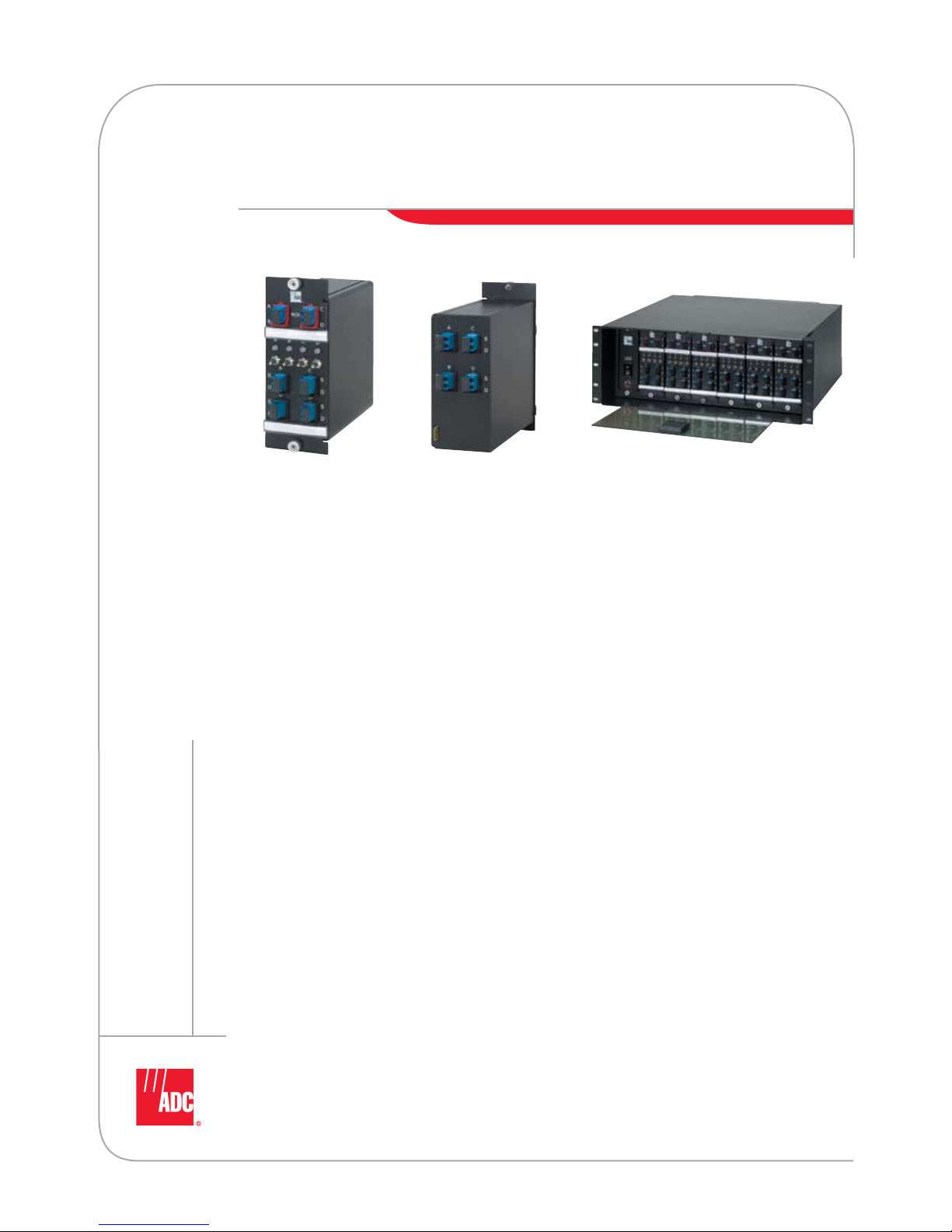
Module Front Module Rear Chassis Open
Features
Two density options:
• The 3RU chassis houses 6 modules to
provide 24 fiber terminations (12 pairs)
using simplex connectors (SC, FC, ST).
• The 4RU chassis houses 6 modules to
provide 48 fiber terminations (24 pairs)
using small-form-factor connectors (LC).
Functionality:
• Each module contains pairs of “Source” and
“Destination” fibers plus optional monitor
ports and a switch for emergency patching.
• Accommodates 1310 and 1550 singlemode
wavelengths (switch wavelength range is
1290-1330 and 1525-1610).
• Connector ports on front and rear may be
SC, FC, ST or LC.
• IL through module is approximately 0.5 dB
(final specifications TBD).
• Module port is configurable to 90/10, 95/5
or 99/1 split ratios.
Module specifications:
• Modules may be added to the chassis
as needed.
• “Source” and “Destination” terminations
may be made by either splicing raw cable
to pigtails attached to the modules or by
routing connectorized patch cords to the
back of the modules.
• Manual switch on front of module to
change to “Patched” operation.
• LED indicators for “Normal” and
“Patched” operations.
• Modules are available with or without
monitor ports on the front.
Chassis specification:
• 19" EIA flush mounting
• Hot swappable power supply
to power switches inside modules
• 110/220 IEC interface
Page 2
2
w w w . a d c . c o m • + 1 - 9 5 2 - 9 3 8 - 8 0 8 0 • 1 - 8 0 0 - 3 6 6 - 3 8 9 1
Pro PatchTM Optical Normal Through Panel
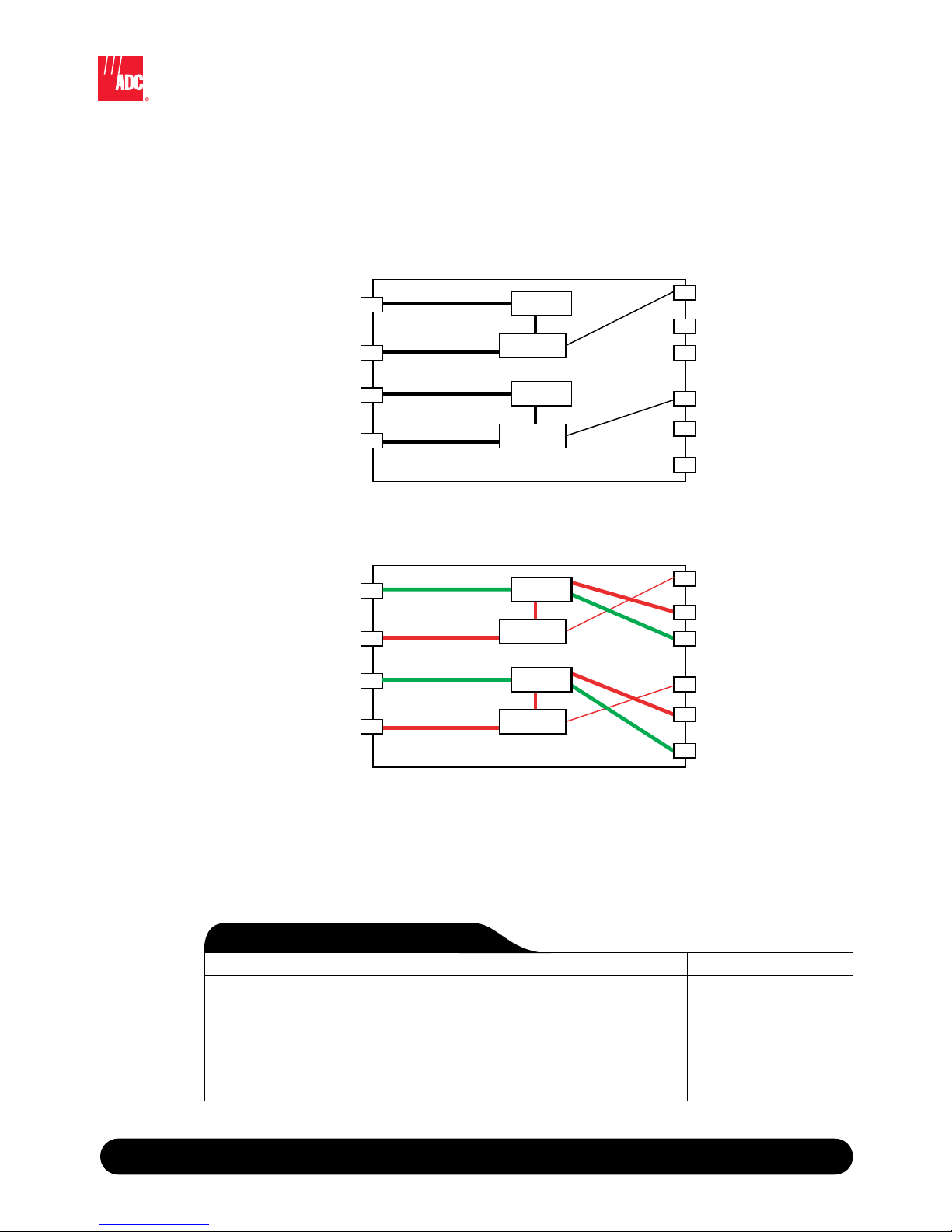
Module Schematics
The new Pro Patch Optical Normal Through Panel provides patch by exception, normal through functionality.
Fiber “Source” and “Destination” connections are located on the rear of the panel, with a normal through
connection between the “Source” and “Destination” ports. To enable patching functionality, a fiber patch
cord is plugged into the front of the panel and a switch is flipped.
9 / 0 6 • 1 0 3 4 4 7 A E
Pro Patch
TM
Optical Normal Through Panel
A Source
A Destination
B Source
B Destination
90%
Monitor
Patched
90%
10%
Monitor
Source
Source
Destination
Destination
Back of Module Front of Module
Switch
90/10 Tap
90/10 Tap
Switch
A Source
A Destination
B Source
B Destination
90/10 Tap
90%
10 %
Monitor
Normal
Switch
90/10 Tap
90%
10%
Switch
Monitor
Source
Source
Destination
Destination
Back of Module Front of Module
Description Catalog Number
Empty chassis with power supply
3 RU chassis with power supply and IEC cord, patch cord storage in rear
3 RU chassis with power supply and IEC cord, splice tray area in rear
4 RU chassis with power supply and IEC cord, patch cord storage in rear
4 RU chassis with power supply and IEC cord, splice tray area in rear
Power supply
Replacement power supply with IEC cord
PPO-3RU-P
PPO-3RU-S
PPO-4RU-P
PPO-4RU-S
PPO-PWR
O r d e r i n g I n f o r m a t i o n
These are preliminary specifications.
Call an ADC distributor for more details. To find a distributior near you visit adc.com/partners.
Page 3

3
w w w . a d c . c o m • + 1 - 9 5 2 - 9 3 8 - 8 0 8 0 • 1 - 8 0 0 - 3 6 6 - 3 8 9 1
The information below explains the ordering numbers contained in the charts on this page.
Pro PatchTM Optical Normal Through Panel
Pro Patch™ Preconfigured Panels
9 / 0 6 • 1 0 3 4 4 7 A E
Pro Patch
TM
Optical Normal Through Panel
Modules Loaded
1-6 Number of modules loaded
Catalog Number
PPO - __ __ __ __ __ __ __ __ - __
Panel Size
3 3 RU
4 4 RU
Rear Cable Management/splice
0 Patch cord slack storage
2 Heat shrink splice trays
3 Mass Fusion splice trays
Power Supply
0 No cord
1 With IEC cord
Rear Connector/Splice
2 SMFC
7 SMSC
J SMSC (8º angled polish)
8 SMLC (4 RU only)
0 Pigtail for splicing
4 SMST
Monitor Split Style
0 No monitor
A 90/10
B 95/5
C 99/1
Front Patch Connector Style
2 SMFC
7 SMSC
J SMSC (8º angled polish)
8 SMLC (4 RU only)
4 SMST
Switch Type
0 Standard individual
2 Pair switch together
Monitor Port Connector
0 No monitor
F SMFC (8º angled polish)
J SMSC (8º angled polish)
Q SMALC (4 RU only)
Custom configurations are available. Please contact ADC Technical Assistance Center.
Page 4

SPEC SHEET
Pro Patch™ Modules
The information below explains the ordering numbers contained in the charts on this page.
Catalog Number
PPO-M __ __ __ __ __ __
Panel Size
3 3 RU
4 4 RU
Front Patch Connector Style
2 SMFC
7 SMSC
J SMSC (8º angled polish)
4 SMST
8 SMLC (4 RU only)
Switch Type
0 Standard individual
2 Pair switch together
Monitor Port Connector
0 No monitor
F SMFC (8º angled polish)
J SMSC (8º angled polish)
Q SMALC (4 RU only)
Rear Connector/Splice
7 SMSC
J SMSC (8º angled polish)
8 SMLC (4 RU only)
0 Pigtail for splicing
4 SMST
2 SMFC
Monitor Split Style
0 No monitor
A 90/10
B 95/5
C 99/1
Web Site: www.adc.com
From North America, Call Toll Free: 1-800-366-3891 • Outside of North America: +1-952-938-8080
Fax: +1-952-917-3237 • For a listing of ADC’s global sales office locations, please refer to our Web site.
ADC Telecommunications, Inc., P.O. Box 1101, Minneapolis, Minnesota USA 55440-1101
Specifications published here are current as of the date of publication of this document. Because we are continuously
improving our products, ADC reserves the right to change specifications without prior notice. At any time, you may
verify product specifications by contacting our headquarters office in Minneapolis. ADC Telecommunications, Inc.
views its patent portfolio as an important corporate asset and vigorously enforces its patents. Products or features
contained herein may be covered by one or more U.S. or foreign patents. An Equal Opportunity Employer
103447AE 9/06 Revison © 2006 ADC Telecommunications, Inc. All Rights Reserved
Custom configurations are available. Please contact ADC Technical Assistance Center.
 Loading...