

Page 1
ADCP-80-545
March 2006
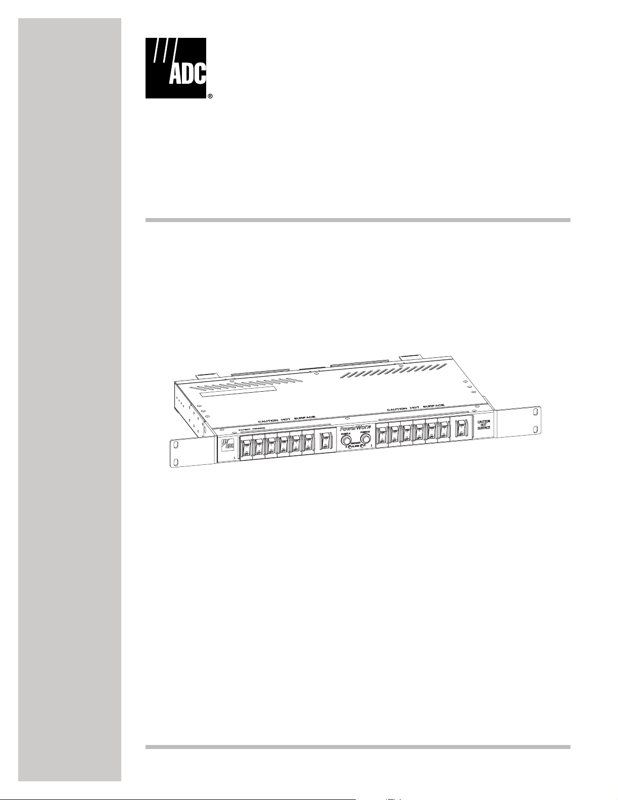
PowerWorx® Power Distribution Products
Select Series Circuit Breaker
Power Distribution Panel User Manual
Issue 3
17943-A
1361498 Rev A
Page 2

ADCP-80-545 • Issue 3 • March 2006 • Preface
COPYRIGHT
© 2006, ADC Telecommunications, Inc.
All Rights Reserved
Printed in the U.S.A.
REVISION HISTORY
ISSUE DATE REASON FOR CHANGE
1 09/2002 Original.
2 09/2004 Added warning not to use one bus only (three places). Updated customer information.
3 03/2006 Corrected wire color.
LIST OF CHANGES
The technical changes incorporated into this issue are listed below.
PAGE IDENTIFIER DESCRIPTION OF CHANGE
26 Step 9 Changed wire color from black to white and vice versa.
27 Figure 20 Changed wire color from black to white and vice versa.
TRADEMARK INFORMATION
ADC and PowerWorx are registered trademarks of ADC Telecommunications, Inc.
DISCLAIMER OF LIABILITY
Contents herein are current as of the date of publication. ADC reserves the right to change the contents without prior notice. In no
event shall ADC be liable for any damages resulting from loss of data, loss of use, or loss of profits and ADC further
disclaims any and all liability for indirect, incidental, special, consequential or other similar damages. This disclaimer of
liability applies to all products, publications and services during and after the warranty period.
This publication may be verified at any time by contacting ADC’s Technical Assistance Center at 1-800-366-3891, extension 73475
(in U.S.A. or Canada) or 952-917-3475 (outside U.S.A. and Canada), or by e-mail to connectivity_tac@adc.com.
Page ii
ADC Telecommunications, Inc.
P.O. Box 1101, Minneapolis, Minnesota 55440-1101
In U.S.A. and Canada: 1-800-366-3891
Outside U.S.A. and Canada: (952) 938-8080
Fax: (952) 917-1717
Page 3

TABLE OF CONTENTS
Content Page
ABOUT THIS MANUAL . . . . . . . . . . . . . . . . . . . . . . . . . . . . . . . . . . . . . . . . . . . . . . . . . . . . . . . . . . . . . . . . . . . . . . . . . v
STANDARDS CERTIFICATION . . . . . . . . . . . . . . . . . . . . . . . . . . . . . . . . . . . . . . . . . . . . . . . . . . . . . . . . . . . . . . . . . . . . v
ADMONISHMENTS . . . . . . . . . . . . . . . . . . . . . . . . . . . . . . . . . . . . . . . . . . . . . . . . . . . . . . . . . . . . . . . . . . . . . . . . . . . v
GENERAL SAFETY PRECAUTIONS . . . . . . . . . . . . . . . . . . . . . . . . . . . . . . . . . . . . . . . . . . . . . . . . . . . . . . . . . . . . . . . . . v
1 PRODUCT DESCRIPTION . . . . . . . . . . . . . . . . . . . . . . . . . . . . . . . . . . . . . . . . . . . . . . . . . . . . . . . . . . . . . . . . . . 1
1.1 Product Functions and Features. . . . . . . . . . . . . . . . . . . . . . . . . . . . . . . . . . . . . . . . . . . . . . . . . . . . . . . . 1
1.2 Circuit Breaker Panel Components . . . . . . . . . . . . . . . . . . . . . . . . . . . . . . . . . . . . . . . . . . . . . . . . . . . . . . 1
1.3 Packaged Hardware. . . . . . . . . . . . . . . . . . . . . . . . . . . . . . . . . . . . . . . . . . . . . . . . . . . . . . . . . . . . . . . . 3
1.4 Options . . . . . . . . . . . . . . . . . . . . . . . . . . . . . . . . . . . . . . . . . . . . . . . . . . . . . . . . . . . . . . . . . . . . . . . . 4
1.5 Accessories . . . . . . . . . . . . . . . . . . . . . . . . . . . . . . . . . . . . . . . . . . . . . . . . . . . . . . . . . . . . . . . . . . . . . 4
1.6 Mounting . . . . . . . . . . . . . . . . . . . . . . . . . . . . . . . . . . . . . . . . . . . . . . . . . . . . . . . . . . . . . . . . . . . . . . . 5
1.7 Power Buses. . . . . . . . . . . . . . . . . . . . . . . . . . . . . . . . . . . . . . . . . . . . . . . . . . . . . . . . . . . . . . . . . . . . . 5
1.8 Circuit Breakers . . . . . . . . . . . . . . . . . . . . . . . . . . . . . . . . . . . . . . . . . . . . . . . . . . . . . . . . . . . . . . . . . . 5
1.9 Input/Output Voltage . . . . . . . . . . . . . . . . . . . . . . . . . . . . . . . . . . . . . . . . . . . . . . . . . . . . . . . . . . . . . . . 6
1.10 Input Power Connections . . . . . . . . . . . . . . . . . . . . . . . . . . . . . . . . . . . . . . . . . . . . . . . . . . . . . . . . . . . . 6
1.11 Output Power Connections . . . . . . . . . . . . . . . . . . . . . . . . . . . . . . . . . . . . . . . . . . . . . . . . . . . . . . . . . . . 6
1.12 Ground Connections . . . . . . . . . . . . . . . . . . . . . . . . . . . . . . . . . . . . . . . . . . . . . . . . . . . . . . . . . . . . . . . 7
1.13 Alarm Operation and Connections . . . . . . . . . . . . . . . . . . . . . . . . . . . . . . . . . . . . . . . . . . . . . . . . . . . . . . 7
1.14 LED Indicators. . . . . . . . . . . . . . . . . . . . . . . . . . . . . . . . . . . . . . . . . . . . . . . . . . . . . . . . . . . . . . . . . . . . 7
1.15 Cooling . . . . . . . . . . . . . . . . . . . . . . . . . . . . . . . . . . . . . . . . . . . . . . . . . . . . . . . . . . . . . . . . . . . . . . . . 8
1.16 Specifications . . . . . . . . . . . . . . . . . . . . . . . . . . . . . . . . . . . . . . . . . . . . . . . . . . . . . . . . . . . . . . . . . . . . 8
2 BEFORE STARTING INSTALLATION . . . . . . . . . . . . . . . . . . . . . . . . . . . . . . . . . . . . . . . . . . . . . . . . . . . . . . . . . . 10
2.1 General Installation Recommendations . . . . . . . . . . . . . . . . . . . . . . . . . . . . . . . . . . . . . . . . . . . . . . . . . 10
2.2 Unpacking and Inspection. . . . . . . . . . . . . . . . . . . . . . . . . . . . . . . . . . . . . . . . . . . . . . . . . . . . . . . . . . . 11
2.3 Installation Tools Required . . . . . . . . . . . . . . . . . . . . . . . . . . . . . . . . . . . . . . . . . . . . . . . . . . . . . . . . . . 11
2.4 Materials Required . . . . . . . . . . . . . . . . . . . . . . . . . . . . . . . . . . . . . . . . . . . . . . . . . . . . . . . . . . . . . . . 11
3 INSTALLATION . . . . . . . . . . . . . . . . . . . . . . . . . . . . . . . . . . . . . . . . . . . . . . . . . . . . . . . . . . . . . . . . . . . . . . . . 12
3.1 Test Continuity . . . . . . . . . . . . . . . . . . . . . . . . . . . . . . . . . . . . . . . . . . . . . . . . . . . . . . . . . . . . . . . . . . 12
3.2 Mounting Procedure. . . . . . . . . . . . . . . . . . . . . . . . . . . . . . . . . . . . . . . . . . . . . . . . . . . . . . . . . . . . . . . 14
3.3 Chassis Ground Connections . . . . . . . . . . . . . . . . . . . . . . . . . . . . . . . . . . . . . . . . . . . . . . . . . . . . . . . . . 16
3.4 External Alarm System Connections . . . . . . . . . . . . . . . . . . . . . . . . . . . . . . . . . . . . . . . . . . . . . . . . . . . . 16
3.5 Output Power Connections . . . . . . . . . . . . . . . . . . . . . . . . . . . . . . . . . . . . . . . . . . . . . . . . . . . . . . . . . . 17
3.6 Input Power Connections . . . . . . . . . . . . . . . . . . . . . . . . . . . . . . . . . . . . . . . . . . . . . . . . . . . . . . . . . . . 18
3.7 Protective Cover Installation/Removal . . . . . . . . . . . . . . . . . . . . . . . . . . . . . . . . . . . . . . . . . . . . . . . . . . 20
3.8 Cable Management Bar Installation (Accessory Item) . . . . . . . . . . . . . . . . . . . . . . . . . . . . . . . . . . . . . . . . 21
3.9 Circuit Designation Card and Voltage Label. . . . . . . . . . . . . . . . . . . . . . . . . . . . . . . . . . . . . . . . . . . . . . . 21
4 TESTING . . . . . . . . . . . . . . . . . . . . . . . . . . . . . . . . . . . . . . . . . . . . . . . . . . . . . . . . . . . . . . . . . . . . . . . . . . . . 22
4.1 Power and Alarm Indication Test . . . . . . . . . . . . . . . . . . . . . . . . . . . . . . . . . . . . . . . . . . . . . . . . . . . . . . 22
4.2 Connection Polarity Test . . . . . . . . . . . . . . . . . . . . . . . . . . . . . . . . . . . . . . . . . . . . . . . . . . . . . . . . . . . . 22
4.3 Alarm Contacts Test . . . . . . . . . . . . . . . . . . . . . . . . . . . . . . . . . . . . . . . . . . . . . . . . . . . . . . . . . . . . . . . 22
5 OPERATION . . . . . . . . . . . . . . . . . . . . . . . . . . . . . . . . . . . . . . . . . . . . . . . . . . . . . . . . . . . . . . . . . . . . . . . . . . 23
ADCP-80-545 • Issue 3 • March 2006 • Preface
© 2006, ADC Telecommunications, Inc.
Page iii
Page 4

ADCP-80-545 • Issue 3 • March 2006 • Preface
TABLE OF CONTENTS
Content Page
5.1 Circuit Breaker Operation. . . . . . . . . . . . . . . . . . . . . . . . . . . . . . . . . . . . . . . . . . . . . . . . . . . . . . . . . . . 23
5.2 Connecting New Equipment . . . . . . . . . . . . . . . . . . . . . . . . . . . . . . . . . . . . . . . . . . . . . . . . . . . . . . . . . 23
6 MAINTENANCE . . . . . . . . . . . . . . . . . . . . . . . . . . . . . . . . . . . . . . . . . . . . . . . . . . . . . . . . . . . . . . . . . . . . . . . . 24
6.1 Inspection . . . . . . . . . . . . . . . . . . . . . . . . . . . . . . . . . . . . . . . . . . . . . . . . . . . . . . . . . . . . . . . . . . . . . 24
6.2 Power LED Indicator Replacement. . . . . . . . . . . . . . . . . . . . . . . . . . . . . . . . . . . . . . . . . . . . . . . . . . . . . 24
6.3 Circuit Breaker Replacement . . . . . . . . . . . . . . . . . . . . . . . . . . . . . . . . . . . . . . . . . . . . . . . . . . . . . . . . 25
7 CUSTOMER INFORMATION AND ASSISTANCE. . . . . . . . . . . . . . . . . . . . . . . . . . . . . . . . . . . . . . . . . . . . . . . . . . . 28
Page iv
© 2006, ADC Telecommunications, Inc.
Page 5

ABOUT THIS MANUAL
This manual describes the PowerWorx Select Series Circuit Breaker Power Distribution Panel,
hereinafter called “circuit breaker panel” or “panel”, and its available options and accessories.
Also provided is the information required to install, test, and operate the circuit breaker panel.
The Select Series circuit breaker panel is used to supply protected dc power to the –24 Vdc or
–48 Vdc powered equipment that is typically installed in a central office, multimedia headend,
remote site, CEV, or other restricted access location requiring protected dc power.
STANDARDS CERTIFICATION
The Select Series circuit breaker panel complies with the applicable sections of the following
standards: UL, NEC 2002, NEBS Level 3, IEC, and CE.
ADMONISHMENTS
Important safety admonishments are used throughout this manual to warn of possible hazards to
persons or equipment. An admonishment identifies a possible hazard and then explains what
may happen if the hazard is not avoided. The admonishments — in the form of Dangers,
Warnings, and Cautions — must be followed at all times. These warnings are flagged by use of
the triangular alert icon (seen below), and are listed in descending order of severity of injury or
damage and likelihood of occurrence.
ADCP-80-545 • Issue 3 • March 2006 • Preface
Danger: Danger is used to indicate the presence of a hazard that will cause severe personal
injury, death, or substantial property damage if the hazard is not avoided.
Warn ing: Warning is used to indicate the presence of a hazard that can cause severe personal
injury, death, or substantial property damage if the hazard is not avoided.
Caution: Caution is used to indicate the presence of a hazard that will or can cause minor
personal injury or property damage if the hazard is not avoided.
GENERAL SAFETY PRECAUTIONS
-
Warn ing: The circuit breaker panel uses electrical voltage and current levels that may be
considered an electrical hazard per GR-1089. Only qualified personnel should be allowed to
install, operate, maintain, or otherwise come into contact with this equipment when energized.
Only insulated tools should be used on energized elements of the panel.
Warn ing: Disconnect or turn off the power before connecting the circuit breaker panel input or
output wires. This may require turning off the system office battery input at the office
distribution panel or turning-off the appropriate circuit breaker at the panel.
© 2006, ADC Telecommunications, Inc.
Page v
Page 6

ADCP-80-545 • Issue 3 • March 2006 • Preface
Caution: Using the wrong circuit breaker may cause damage to the protected equipment or the
circuit breaker panel. When replacing a circuit breaker, make sure the replacement breaker does
not exceed 50 Amps and is the correct type and correct current rating as required by the
protected equipment.
Warn ing: Wet conditions increase the potential for receiving an electrical shock when
installing or using electrically-powered equipment. To prevent electrical shock, never install or
use electrical equipment in a wet location or during a lightning storm.
Page vi
© 2006, ADC Telecommunications, Inc.
Page 7

1 PRODUCT DESCRIPTION
This section describes the functions and features provided by the PowerWorx Select Series
circuit breaker panel and provides a table of product specifications.
1.1 Product Functions and Features
The Select Series circuit breaker panel, shown on the cover of this manual, supplies protected
dc power to the –24 Vdc and –48 Vdc powered equipment typically installed in a central office,
multimedia headend, remote site, CEV, or other restricted access location. The panel provides
the following basic functions and features:
• Self-configuring voltage (–24 Vdc or –48 Vdc) capability to simplify installation and
allow one panel to fit most dc voltage applications.
• Ampere ratings and ON/OFF designations clearly marked on each circuit breaker.
• Eight single-pole circuit breaker mounting positions (two-pole breakers require two
mounting positions) per bus.
• Two sets of mounting brackets to permit panel installation in a 19- or 23-inch, WECO or
EIA, equipment rack.
ADCP-80-545 • Issue 3 • March 2006
• Mounts within 1 rack space (1.75 inches).
• Dual-bus power feeds with a maximum input rating of 100 Amps per bus.
Warn ing: Use of one bus only on a dual bus panel will result in false alarms for the unused
bus. Power is required on both buses on a dual bus panel for normal operation.
• Two-hole compression-lug style terminals for input power connections. Screw-down
barrier terminal strips for output power connections.
• Screw-down or wire-wrap pin terminals (option) for alarm connections. A tripped breaker
or loss of power initiates relay operation which opens one set of relay contacts (form C)
and closes another set. The alarm contacts may be used to open or close a loop connected
to an external alarm system.
• Two field-replaceable high-brilliance power indicators (green LED’s) and two nonreplaceable high brilliance alarm indicators (red LED’s).
• Two grounding studs to ensure reliable ground connectivity.
• Easy to remove/replace plastic protective covers mount over the input and output terminal
connections to enhance safety.
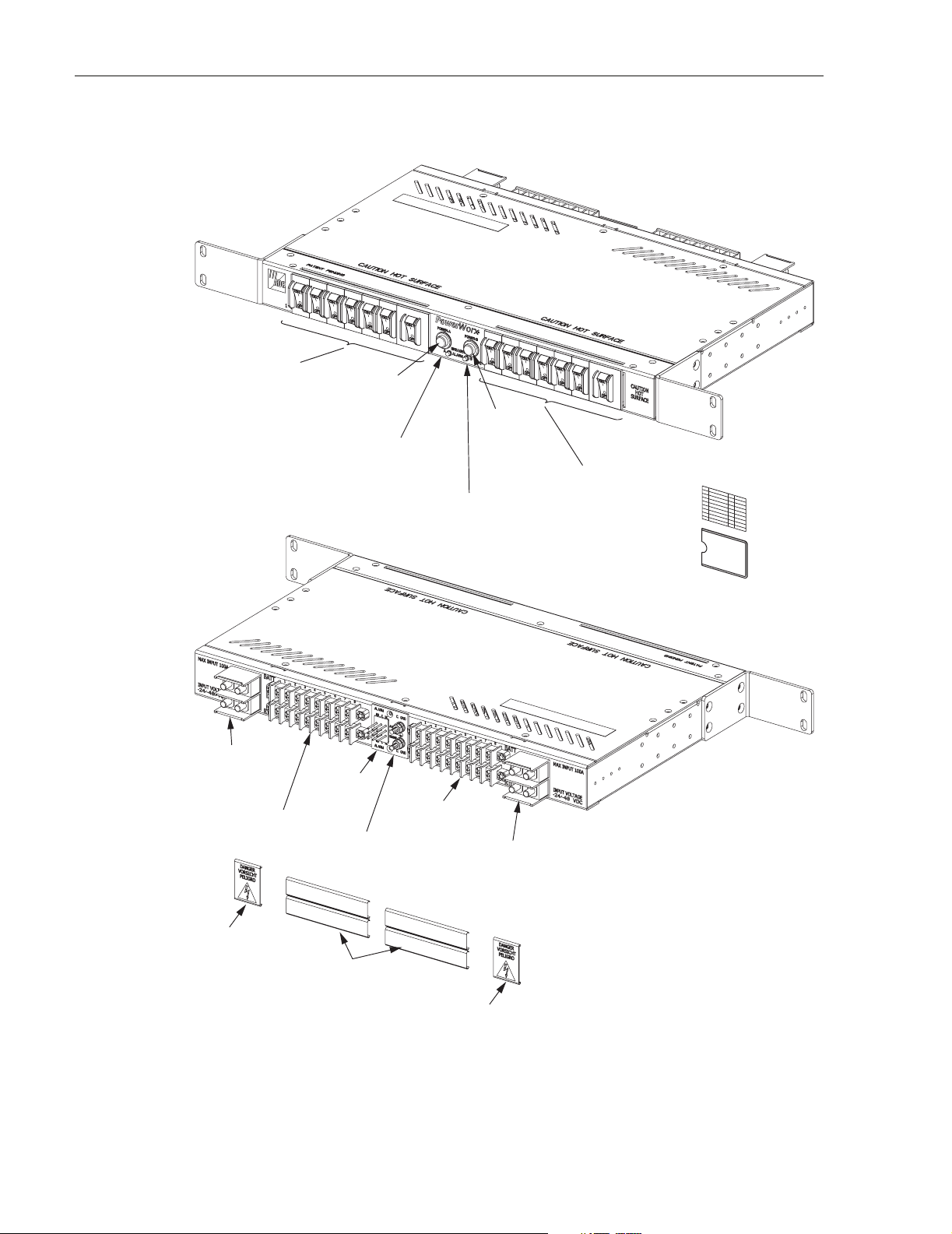
1.2 Circuit Breaker Panel Components
The panel consists of the components shown in Figure 1. Panel components are either mounted
on or housed within a putty white powder-painted sheet metal enclosure. The circuit breakers,
the power LED indicators, and the breaker alarm LED indicators are mounted on the front side
of the enclosure. Unused circuit breaker mounting positions are covered with blanks.
Replacement circuit breakers, lug terminals, a cable management bar, and other items are
available separately as accessory items.
© 2006, ADC Telecommunications, Inc.
Page 1
Page 8
ADCP-80-545 • Issue 3 • March 2006
1 TO 8 CIRCUIT BREAKERS
(BLANK PANEL IF NO
CIRCUIT BREAKER)
BUS B INPUT
POWER TERMINALS
BUS B OUTPUT
POWER TERMINALS
BUS A
POWER-ON
INDICATOR
(GREEN LED)
BUS A
CIRCUIT BREAKER
ALARM INDICATOR (RED LED)
FRONT VIEW
ALARM INDICATOR (RED LED)
ALARM
TERMINALS
BUS A OUTPUT
POWER TERMINALS
CHASSIS
GROUNDING
STUDS
BUS B
POWER-ON
INDICATOR
(GREEN LED)
BUS B
CIRCUIT BREAKER
BUS A INPUT
POWER TERMINALS
1 TO 8 CIRCUIT BREAKERS
(BLANK PANEL IF NO
CIRCUIT BREAKER)
DESIGNATION CARD
AND CARD HOLDER
COVER FOR
INPUT POWER
TERMINALS
Page 2
© 2006, ADC Telecommunications, Inc.
COVERS FOR
OUTPUT POWER
TERMINALS
COVER FOR
REAR VIEW
INPUT POWER
TERMINALS
Figure 1. Select Series Circuit Breaker Panel (Typical)
17939-A
Page 9
The input power terminals, output power terminals, alarm terminals, and grounding studs are
mounted on the rear side of the panel enclosure. The plastic protective covers install over the
input and output power terminals. The covers prevent accidental contact with the terminals
when power is applied to the panel. The internal bus wiring and alarm relay circuit boards are
mounted within the enclosure and are not user accessible.
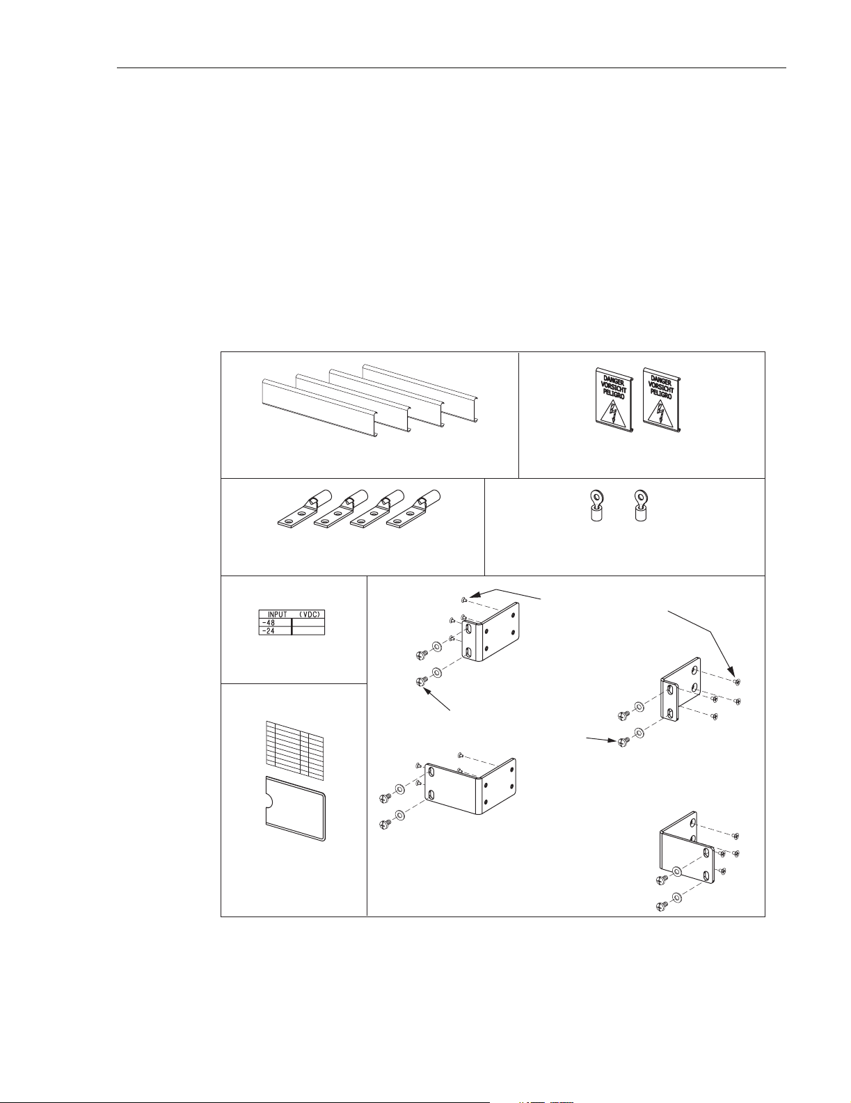
1.3 Packaged Hardware
The Select Series circuit breaker panel includes various hardware components that are packaged
separately and shipped in the carton with the basic panel. The packaged hardware components
are shown in Figure 2 and include the following items:
ADCP-80-545 • Issue 3 • March 2006
REAR COVERS FOR OUTPUT
POWER/ALARM TERMINAL BLOCK
2-HOLE LUGS FOR
2 AWG WIRE
VO LTAGE
LABEL
REAR COVERS FOR INPUT
POWER TERMINAL BLOCK
#10 RING TERMINALS FOR
12-10 AWG WIRE
5/16-INCH (7.936 MM) 8-32
FLAT-HEAD SCREWS
ORIENTATION FOR
19-INCH RACK INSTALLATION
3/8-INCH (9.525 MM) 12-24
SCREWS AND #12 WASHERS
ORIENTATION FOR
23-INCH RACK INSTALLATION
DESIGNATION CARD
AND CARD HOLDER
UNIVERSAL MOUNTING BRACKETS
Figure 2. Packaged Hardware Components
• One set of 19-inch mounting brackets
AND SCREWS
17942-A
Page 3
© 2006, ADC Telecommunications, Inc.
Page 10

ADCP-80-545 • Issue 3 • March 2006
• One set of 23-inch mounting brackets
• 5/16-inch long, Phillips drive, 8-32 flat-head thread-forming screws (10 provided which
includes 2 spares) - Used to secure the mounting brackets to the panel.
• 3/8-inch long, combination drive, 12-24 pan-head screws (4) and #12 flat washers (4) Used to secure the panel mounting brackets to the equipment rack.
• 2-hole lugs (4) for #2 AWG wire - Used to attach the BATTERY and RETURN cables to
the power input terminals. Also available as an accessory item.
• #10 ring terminals (2) for 12–10 AWG wire - Used to connect the grounding cables to the
grounding studs.
• Rear protective input terminal covers (2) and output terminal covers (4) - Used to prevent
accidental contact with the power input and output terminals.
• Voltage label - Used to indicate the voltage of the panel (–24 or –48 Vdc).
• Designation cards (2) and card holder - Used to record information about the protected
equipment. The card holder has a pressure sensitive adhesive backing to permit attachment
to the panel, the rack, or a location close to the panel. The card inserts into the card holder.
Two types of cards are provided. Also available as an accessory item.
1.4 Options
The following ordering options are available for the Select Series circuit breaker panel:
• Circuit breaker configurations - Circuit breakers may be specified in any combination of
• Circuit breaker ratings - Both 1-pole and 2-pole circuit breakers are used with the panel.
• Alarm contact connections - Either screw-down terminals or wire-wrap pin terminals may
1.5 Accessories
The following accessories are available for the Select Series circuit breaker panel:
• Circuit breakers - 1-pole breakers with a rating of 1, 3, 5, 10, 15, and 20 Amps and 2-pole
• 2-hole compression lugs - Used to attach the BATT and RTN cables to the power input
values as long as the total current draw on each bus does not exceed 100 Amps. A
maximum of eight 1-pole breakers or four 2-pole breaker may be installed per bus.
The 1-pole breakers are available with 1, 3, 5, 10, 15, or 20 Amp ratings. The 2-pole
breakers are available with 26, 30, 36, 40, and 50 Amp ratings.
be specified for the alarm contact connections.
breakers with a rating of 26, 30, 36, 40, and 50 Amps are available.
terminals. Available to fit 2, 4, 6, or 14 AWG wire.
• Cable management bar - Use to secure the output power wires at the rear of the panel.
• Designation cards (2) and card holder - Used to record information about the protected
equipment. The card holder has a pressure sensitive adhesive backing to permit attachment
Page 4
© 2006, ADC Telecommunications, Inc.
Page 11

to the panel, the rack, or a location close to the panel. The cards insert into the card holder.
Two types of cards are provided.
1.6 Mounting
The Select Series circuit breaker panel can be mounted in either a 19- or 23-inch (482.6 or
584.2 mm) equipment rack. Two sets of mounting brackets, one set for 19-inch racks and one
set for 23-inch racks, are provided with the panel. The panel can be flush mounted or recessed 1,
2, 3, or 4 inches (25.4, 50.8, 76.2 or 91.6 mm). The mounting brackets are slotted to allow the
panel to be mounted in racks with WECO 1.0-inch (25.4 mm) or EIA 1.25-inch (31.8 mm) hole
spacing. The slots also compensate for vertical rack differences so that the panel can be
mounted in either 1.75- or 2-inch (44.5 or 50.8 mm) rack spaces. The panel requires one open
rack space above and below the chassis for heat dissipation.
1.7 Power Buses
The Select Series circuit breaker panel has two isolated power bus (power feed) circuits which
are designated as the A and B power buses. Each power bus circuit distributes the input power
to the corresponding A or B output power circuit. In each bus circuit, current flows from the
input power terminals, through the circuit breakers, to the output power terminals.
ADCP-80-545 • Issue 3 • March 2006
Warn ing: Use of one bus only on a dual bus panel will result in false alarms for the unused
bus. Power is required on both buses on a dual bus panel for normal operation.
The maximum current capacity of each power bus circuit is 100 Amps. The total output current
capacity of the circuit breakers on each bus must not exceed 100 Amps. The maximum current
rating is marked on the circuit breaker panel rear side. The power dissipation of the panel is 160
watts maximum per panel (80 watts per bus).
1.8 Circuit Breakers
The circuit breakers are magnetic actuation, manual reset, replaceable, 60 Vdc rated circuit
breakers, with finger guard and ampere markings. Both 1- pole and 2-pole breakers are used
with the panel. The 1-pole breakers are available with 1, 3, 5, 10, 15, and 20 Amp ratings. The
2-pole breakers are available with 26, 30, 36, 40, and 50 Amp ratings. Each 1-pole or 2-pole
circuit breaker can be field-replaced by another 1-pole or 2-pole breaker with a different current
rating or time delay. A breaker with a higher current rating may be installed as a replacement as
long as the total current draw of the affected bus does not exceed 100 Amps.
The circuit breaker panel will accommodate from one to eight 1-pole circuit breakers per bus or
from one to four 2-pole circuit breakers per bus. Both 1-pole and 2-pole breakers may be
combined together on the same bus. Each circuit breaker position that does not have a breaker
installed will be filled with a black plastic plate. Any circuit breaker mounting positions that are
left blank when the panel is ordered cannot be fitted with field-installed circuit breakers.
© 2006, ADC Telecommunications, Inc.
Page 5
Page 12

ADCP-80-545 • Issue 3 • March 2006
The circuit breakers are of the type called “short delay.” The trip times of short delay circuit
breakers are a function of the percent of rated current, as indicated in Table 1. The circuit
breaker will trip (open) and the switch will move to the off position (bottom pushed in) when
the circuit current exceeds the capacity of the circuit breaker. To reset a circuit breaker, push the
switch to the on position (top pushed in).
100% 135% 150% 200% 400% 600% 800% 1000% 1200%
NO
TRIP
Circuit breakers are field-replaceable. Please contact ADC Technical Support if replacement is
required (refer to Section 7, Customer Information and Assistance, on page 28).
1.9 Input/Output Voltage
The Select Series circuit breaker panel accepts an input voltage of either –24 Vdc (nominal) on
both buses or –48 Vdc (nominal) on both buses. For –24 Vdc operation, the voltage can fall
within –21 to –30 Vdc. For –48 Vdc operation, the voltage can fall within a range of –42 to –56
Vdc. The output voltage is the same value as the applied input voltage.
.300-
7.00
Table 1. Short Delay Trip Times in Seconds
PERCENT OF RATED CURRENT
.200-
5.00
.100-
2.00
.030-
.500
.008-
.300
.006-
.150
.005-
.100
.005-
.100
1.10 Input Power Connections
Input power is supplied to the Select Series circuit breaker panel through the A and B input power
terminal blocks. Each input terminal block includes two pairs of studs that are used for connecting
the BATT (battery –) and RTN (return +) input power cables. Each pair of studs is mounted on
0.625 inch centers and accepts various size 2-hole compression lugs. Compression lugs for 2, 4, 6,
and 14 AWG wire are available as accessory items. Nuts with captive washers are included to
secure the compression lugs to the studs. The input terminal blocks are located on the rear side of
the panel. The minimum recommended wire size for the input power wiring is 2 AWG.
1.11 Output Power Connections
Output power is supplied to the protected equipment through the A and B output power terminal
blocks. Screw-down barrier terminal strips are used for the output power terminal blocks. Each
terminal block consists of eight pairs of screw down terminals equipped with 8-32 screws. Each
pair of terminals is used for connecting the battery (BATT) and return (RTN) output power
wiring to the protected equipment. Each terminal will accept a compression-type lug terminal
with a maximum width of 0.378 inches. Copper wire in sizes ranging from #8–16 AWG may be
used for the output power wiring. The output power terminal blocks are located on the rear side
of the panel.
Page 6
© 2006, ADC Telecommunications, Inc.
Page 13

1.12 Ground Connections
Two #10 studs (with nuts and captive washers) are provided on the rear side of the circuit breaker
panel for grounding the chassis. The ground connection is used to attach grounding cables to the
chassis. Two 10 AWG copper wires are recommended for the grounding cables. Two #10 ring
terminals for use with 10 AWG wire are provided for connecting the grounding cables to the
grounding studs.
1.13 Alarm Operation and Connections
The Select Series circuit breaker panel contains circuitry that opens and closes a set of form C
relay alarm contacts when a circuit breaker trips or when power to either power bus is lost.
These contacts may be used to open or close a loop connected to an external alarm system.
During normal operation (power applied), the normally open (NO) contacts remain open and
the normally closed (NC) contacts remain closed. When a circuit breaker trips or when power to
a power bus is lost, the NO contacts close creating a connection between NO and common (C)
terminals; and the NC contacts open creating an open circuit between NC and C terminals. The
rating for the alarm relay contacts is 110 Vdc/125 Vac maximum voltage, 1.0 Amp maximum
switching current.
ADCP-80-545 • Issue 3 • March 2006
Both screw-down terminals and wire-wrap pin terminals are available (option) for the alarm
terminal connections. Two sets of alarm contact connections are provided when the panel is
equipped with screw down terminals and three sets of contact connections are provided when
the panel is equipped with wire-wrap pins. The alarm terminals are labeled ALARM and are
located on the rear side of the panel.
The screw-down terminal connections consist of six 3-48 screw terminals mounted in a barrier
type terminal block. The screw terminals are mounted on 0.250 inch (6.350 mm) centers with a
maximum distance between barriers of 0.20 inch (5.08 mm). Two sets of three terminals
(labeled NO, C, and NC) are provided for connection with external alarm systems. The screwdown terminals will accept #16 to #30 AWG copper wire.
The wire wrap pin terminal connections consist of nine wire-wrap pins mounted in a terminal
block. Three sets of three wire wrap pins (NO, C, and NC) are provided for connection with
external alarm systems. The wire wrap pins will accept #22 to #26 AWG copper wire.
1.14 LED Indicators
Two power indicators (green LED) are provided on the front side of the panel. A separate
power indicator is provided for each of the two power output buses (A and B). The power
indicators stay on as long as power is supplied to the corresponding power bus. The power
indicators turn off when power is turned off to the corresponding power bus. Each power
indicator LED can be field-replaced if it fails.
© 2006, ADC Telecommunications, Inc.
Page 7
Page 14

ADCP-80-545 • Issue 3 • March 2006
Two breaker alarm indicators (red LED) are provided on the front side of the panel. A separate
breaker alarm indicator is provided for each of the two power output buses (A and B). The
breaker alarm indicator turns on if any circuit breaker on the corresponding power bus trips.
The breaker alarm indicator turns off when the tripped breaker is placed in the on position. The
breaker alarm indicators cannot be field-replaced.
1.15 Cooling
The Select Series circuit breaker panel relies on convection air flow for cooling. Holes are
provided on the top and bottom of the panel to allow heated air to escape from the panel and
cool air to enter. At least one rack unit of space must be provided above and below the panel to
allow for air circulation.
1.16 Specifications
The specifications for the Select Series circuit breaker panel are listed in Tabl e 2 .
Table 2. Circuit Breaker Panel Specifications
PARAMETER SPECIFICATION REMARKS
Physical
Weight 10 lbs. (4.54 kg)
Dimensions (HxWxD) 1.73 x 17.13 x 11.11 inches
(43.9 x 435 x 282 mm)
Color Putty white
Rack mounting 19- or 23-inch EIA or WECO hole spacing
Electrical
Operating voltages –24 Vdc
–48 Vdc
Input current 100 Amps per bus maximum
Breaker type Magnetic actuation, manual
reset, replaceable
Breaker mounting positions Eight 1-pole per bus (16 total) or
Four 2-pole per bus (8 total
Maximum breaker size 50 Amps
Input terminal type 2-hole compression lug 0.625 inch between centers
Output terminal type Screw down terminal (8-32) Max lug width 0.378 inches
Alarm terminal type Screw down terminal (3-48) Max lug width 0.20 inches
Alarm contact voltage 110 Vac, 125 Vdc maximum
See Figure 3
–21 to –30 Vdc tolerance
–42 to –56 Vdc tolerance
1- pole or 2-pole
Or any combination of 1- and 2pole breakers
Alarm contact current 1 Amp maximum
Grounding connections Two #10 studs #10 ring terminals
Page 8
© 2006, ADC Telecommunications, Inc.
Page 15

ADCP-80-545 • Issue 3 • March 2006
Table 2. Circuit Breaker Panel Specifications, continued
PARAMETER SPECIFICATION REMARKS
Environmental
Operating temperature –5º C to +55º C
Storage temperature –45º C to +85º C
Humidity range 0% to 95% humidity No condensation
Altitude range Up to 13,000 ft. (3.96 km)
Fire rating All components UL94-V1 or
better
Acoustic noise 0 dBA above ambient
Heat dissipation (fully loaded) 160 watts max. at 200 Amps 80 watts per bus
Tor que
Mounting bracket chassis screws 15 pound force-inches 1.7 Newton meters
Mounting bracket rack screws 27 pound force-inches 3.1 Newton meters
Input power terminal nuts 32 pound force-inches 3.6 Newton meters
Output power terminal screws 15 pound force-inches 1.7 Newton meters
Alarm terminal screws 8 pound force-inches 0.9 Newton meters
Grounding stud nuts 23 pound force-inches 2.6 Newton meters
© 2006, ADC Telecommunications, Inc.
Page 9
Page 16

ADCP-80-545 • Issue 3 • March 2006
11.11 INCHES
(282 MM)
10.01 INCHES
(254 MM)
23.00 INCHES
(584.2 MM)
1.125 INCHES
(28.6 MM)
1.73 INCHES
(43.9 MM)
Figure 3. Dimensions of Select Series Circuit Breaker Panel
2 BEFORE STARTING INSTALLATION
This section provides general installation recommendations, unpacking and inspection
procedures, and lists the tools and material required for panel installation.
2.1 General Installation Recommendations
The Select Series circuit breaker panel must be installed in a central office, equipment room,
CEV or other restricted access location. Mount the panel in the uppermost area of the rack to
reduce the exposure of the power wiring.
17.13 INCHES
(435 MM)
22.3 INCHES
(567.7 MM)
17938-A
Route ground, power, and alarm cables to the panel according to local practice and procedures.
After routing the cables, secure them to the equipment rack or to any cable management devices
that are in use. Follow the instructions provided in this manual when connecting the cables to
the panel. Install the protective covers on the rear side of the panel after all the wiring
Page 10
© 2006, ADC Telecommunications, Inc.
Page 17

connections are made and all tests are completed. Do not apply power to the panel until all
wiring and tests are completed.
Warn ing: The circuit breaker panel uses electrical voltage and current levels that may be
considered an electrical hazard per GR-1089. Only qualified personnel should be allowed to
install, operate, maintain, or otherwise come into contact with this equipment when energized.
Only insulated tools should be used on energized elements of the panel.
Warn ing: Wet conditions increase the potential for receiving an electrical shock when
installing or using electrically-powered equipment. To prevent electrical shock, never install or
use electrical equipment in a wet location or during a lightning storm.
2.2 Unpacking and Inspection
Before starting the installation, always open the shipping boxes and verify that all parts have
been received and that no shipping damage has occurred. Use the following procedure to
unpack and inspect the circuit breaker panel:
1. Open the shipping carton and carefully unpack the circuit breaker panel from the
protective packing material.
ADCP-80-545 • Issue 3 • March 2006
2. Check the panel for broken or missing parts. If there are any damages, contact ADC (see
Section 7, Customer Information and Assistance, at the end of this manual) for an RMA
(Return Material Authorization) and to reorder if replacement is required.
2.3 Installation Tools Required
The following tools are required to install the circuit breaker panel:
• Phillips screwdrivers (#1 and #2)
• Flat-blade screwdrivers (medium and large
• Torque screwdriver calibrated in pound-force inches or Newton meters
• Torque wrench calibrated in pound-force inches or Newton meters
• 3/8-inch and 7/16-inch sockets (for torque wrench)
• Wire cutter
• Wire stripper
• Compression lug crimper
• Multimeter
•Heat gun
2.4 Materials Required
The following materials are required to install the circuit breaker panel:
• #2 AWG insulated copper wire for input power wires
• #10 AWG copper wire for ground connections
© 2006, ADC Telecommunications, Inc.
Page 11
Page 18

ADCP-80-545 • Issue 3 • March 2006
• #8–16 AWG insulated copper wire for the output power wires (use black for the RTN wire
and red for the BATT wire)
• #22–26 AWG insulated copper wire for the wire-wrap pin terminal alarm wires or #16–30
AWG insulated copper wire for the screw-down terminal alarm wires.
• Heat-shrink tubing
3 INSTALLATION
This section provides the installation procedures for the Select Series circuit breaker panel.
3.1 Test Continuity
Each Select Series panel is thoroughly tested at the ADC factory before being shipped.
However, before the panel is installed, a continuity test should be performed to verify that no
internal damage has occurred during shipping and handling. Using a multimeter that is set to
perform a continuity check, perform the following tests.
Test 1: Input Battery to Input Return - Connect one test probe to the A input power BATT
(–) terminal and the other test probe to the A input power RTN (+) terminal (see Figure 4).
Verify that no continuity exists between the input power BATT and RTN terminals. Repeat test
procedure for the B input power terminals.
Test 2: Input Battery to Output Battery - Place each of the A power bus circuit breakers in the
ON position. Connect one test probe to the A input power BATT (–) terminal and the other test
probe to the #1 output power BATT (–) terminal on the A output terminal block (see Figure 5).
Verify that continuity exists between the specified terminals. Verify that continuity exists
between the A input power BATT (–) terminal and each of the remaining A output power BATT
terminals. Repeat the same test procedure for the B power bus circuits. Place all circuit
breakers in the OFF position following completion of this test.
TEST 1- POWER BUS B:
VERIFY NO CONTINUITY
EXISTS BETWEEN BATT
AND RTN TERMINALS
TEST 1- POWER BUS A:
VERIFY NO CONTINUITY
EXISTS BETWEEN BATT
AND RTN TERMINALS
17944-A
Page 12
© 2006, ADC Telecommunications, Inc.
Figure 4. Test 1: Input Battery to Input Return
Page 19

ADCP-80-545 • Issue 3 • March 2006
TEST 2- POWER BUS B:
VERIFY CONTINUITY EXISTS
BETWEEN INPUT AND
OUTPUT BATT TERMINALS
TEST 2- POWER BUS A:
VERIFY CONTINUITY EXISTS
BETWEEN INPUT AND
OUTPUT BATT TERMINALS
17945-A
Figure 5. Test 2: Input Battery to Output Battery
Test 3: Input Return to Output Return - Connect one test probe to the A input power RTN
(+) terminal and the other test probe to the #1 output power RTN (+) terminal on the A output
terminal block (see Figure 6). Verify that continuity exists between the specified terminals.
Repeat the test procedure for each of the remaining output power RTN terminals. Repeat the
same test procedure for the B input power terminal block circuits.
Test 4: Alarm Terminals - Connect the test probes alternately between the C and NC terminals
and the C and NO terminals on each set of alarm terminals. Verify that no continuity exists
between the C and NC terminals and that continuity does exist between the C and NO terminals.
If the circuit breaker panel fails any of the specified tests, it is defective and must not be
installed. Contact ADC (see Section 7, Customer Information and Assistance) for an RMA
(Return Material Authorization) and to reorder if replacement is required.
TEST 3- POWER BUS B:
VERIFY CONTINUITY EXISTS
BETWEEN INPUT AND
OUTPUT RTN TERMINALS
Figure 6. Test 3: Input Return to Output Return
TEST 3- POWER BUS A:
VERIFY CONTINUITY EXISTS
BETWEEN INPUT AND
OUTPUT RTN TERMINALS
17946-A
© 2006, ADC Telecommunications, Inc.
Page 13
Page 20

ADCP-80-545 • Issue 3 • March 2006
3.2 Mounting Procedure
The circuit breaker panel can be mounted in either a 19- or 23-inch wide rack. Two sets of
mounting brackets are provided with the panel. Eight 5/16-inch (7.94 mm) long, threadforming, Phillips-drive, 8-32 flat-head screws are provided for attaching the mounting brackets
to the panel. Four 3/8-inch (9.53 mm) long, Phillips-drive, 12-24 pan-head screws and four #12
flat washers are provided for attaching the mounting brackets to the equipment rack.
Caution: When attaching the mounting brackets to the circuit breaker panel, use only the 5/16inch (7.94 mm) long, thread forming, flathead screws provided with the panel. Use of any other
hardware could cause contact with internal parts of the panel. If parts are missing, contact
ADC to order replacement parts.
Use the following procedure to install the circuit breaker panel in the equipment rack:
1. Select the 19- or 23-inch mounting brackets (whichever set is required) and orient for
installation as shown in Figure 7.
2. Attach the brackets to the sides of the circuit breaker panel chassis using the eight 5/16inch (7.94 mm) 8-32 flathead thread-forming screws provided. Tighten screws to 15 pound
force-inches (1.7 Newton meters) of torque to insure grounding.
3. Place the panel in the specified mounting space within the rack as shown in Figure 8.
Note: Provide one rack unit of space above and below the panel for air circulation.
4. Secure the panel to the rack using the four 3/8-inch (9.525 mm) long 12-24 pan-head
screws and #12 flat washers provided (use star washers when required by local practice).
Tighten the screws to 27 pound-force inches (3.1 Newton meters) of torque to insure
grounding.
Page 14
© 2006, ADC Telecommunications, Inc.
Page 21

19-INCH RACK
MOUNTING BRACKETS
23-INCH RACK
MOUNTING BRACKETS
ADCP-80-545 • Issue 3 • March 2006
TIGHTEN MOUNTING SCREWS
TO 15 POUND-FORCE INCHES
(1.7 NEWTON METERS) OF TORQUE
5/16-INCH (7.94 MM)
8-32 FLAT-HEAD
THREAD-FORMING
SCREWS
17936-A
Figure 7. Circuit Breaker Panel Mounting Bracket Installation
TIGHTEN MOUNTING SCREWS
TO 27 POUND-FORCE INCHES
(3.1 NEWTON METERS) OF TORQUE
DETAIL DRAWING OF
MOUNTING SCREWS
AND WASHERS
USE #12 STAR WASHERS INSTEAD OF FLAT
WASHERS IF REQUIRED BY LOCAL PRACTICE
Figure 8. Typical Circuit Breaker Panel Installation in Equipment Rack
© 2006, ADC Telecommunications, Inc.
17931-A
Page 15
Page 22

ADCP-80-545 • Issue 3 • March 2006
3.3 Chassis Ground Connections
Mounting the circuit breaker panel on a grounded metal equipment rack using the metal
mounting brackets provided generally provides a sufficient return path to meet equipment
grounding requirements. However, installation of a separate grounding conductor is strongly
recommended and is often required by local practice or local inspectors. A separate grounding
conductor is always needed when the panel is mounted to non-grounded or non-conducting
material such as a plastic rack or cabinet.
Use the following procedure to connect the panel to an approved office ground source:
1. Obtain two lengths of #10 AWG wire for use as the chassis grounding wires.
2. Terminate one end of each wire with the #10 ring terminals provided (requires crimper).
3. Locate the C GND (chassis ground) studs at the rear of the panel as shown in Figure 9.
4. Connect the ring terminal end of each wire to one of the studs and secure using the nuts
with captive star washers provided (requires 3/8-inch socket). Tighten each stud nut to 23
pound-force inches (2.6 Newton meters) of torque.
DETAIL DRAWING
OF GROUNDING
WIRE CONNECTION
Figure 9. Chassis Ground Connections
5. Route the free end of each chassis grounding wire to an approved office ground source.
6. Cut each chassis grounding wire to length and connect it to the office ground source as
required by local code or practice.
3.4 External Alarm System Connections
Normally open (NO) and normally closed (NC) alarm contacts are provided for connecting the
circuit breaker panel to an external alarm system. Alarm connections are provided through
either screw-down terminals or wire-wrap pins (option) located on the rear side of the panel as
shown in Figure 10. One set of terminals, labeled ALARM, is provided for reporting either a
power failure or tripped circuit breaker alarm.
17932-A
TIGHTEN STUD NUT TO
23 POUND-FORCE INCHES
(2.6 NEWTON METERS)
OF TORQUE
Page 16
© 2006, ADC Telecommunications, Inc.
Page 23

ADCP-80-545 • Issue 3 • March 2006
17947-A
WIRE-WRAP PIN
CONNECTIONS FOR
AUDIO, VISUAL, AND
REMOTE ALARMS
The screw-down type terminal strip can accept #16 to #30 AWG copper wire. Screw-down
terminal alarm wires may be terminated with spade-type compression lugs (maximum width
0.20 inches/5.08 mm) or the wire insulation may be stripped back from the wire end and the
bare wire looped under the screw head. Use a torque screw driver to tighten the terminal screws
to 8 pound-force inches (0.9 Newton meters).
The wire-wrap terminal strip can accept #22 to #26 AWG solid copper wire. Strip back the
insulation approximately 1.5 inches (38.1 mm) before inserting the wire into the wire-wrap tool.
3.5 Output Power Connections
Output power is supplied to the protected equipment through the output power terminal blocks.
Each terminal block consists of eight pairs of screw down terminals equipped with 8-32 screws.
The screw-down terminals are used for connecting the BATT (battery) and RTN (return) output
power wiring to the protected equipment. Copper wire in sizes ranging from #8 to #16 AWG
may be used for the output power wiring. The output power wires may be terminated with
spade-type compression lugs (maximum width 0.378 inches) or the insulation may be stripped
back and the bare wire looped under the screw head.
SCREW-DOWN TERMINAL
CONNECTIONS FOR
REMOTE ALARMS
WIRE-WRAP PIN
ALARM CONNECTIONS
Figure 10. Alarm Contact Connections
SCREW-DOWN TERMINAL
ALARM CONNECTIONS
Two output power terminal blocks, one for power bus A and one for power bus B, are provided.
Connect each pair of output wires to the panel as shown in Figure 11. The terminal pairs are
numbered to correspond with each installed circuit breaker. When fewer than eight circuit
breakers are installed in the corresponding breaker mounting slots, the extra screw terminals are
not connected to the bus and cannot be used. Use a torque screwdriver to tighten the terminal
screws to 15 pound-force inches (1.7 Newton meters) of torque.
© 2006, ADC Telecommunications, Inc.
Page 17
Page 24

ADCP-80-545 • Issue 3 • March 2006
Caution: Connecting the protected equipment to the wrong circuit may cause damage to the
equipment or the circuit breaker panel. Make sure the circuit breaker is the correct type and has
the correct current rating as specified by the protected equipment manufacturer.
Note: The continuous output load of the equipment during normal operation should not
exceed 80% of the rated value of the circuit breaker. This allows some room for
manufacturing tolerances and voltage fluctuations in the plant power mains.
POWER
FEED
TERMINALS
POWER
RETURN
TERMINALS
DETAIL DRAWING OF OUTPUT
TERMINAL BLOCK CONNECTIONS
TIGHTEN TERMINAL SCREWS
TO 15 POUND-FORCE INCHES
(1.7 NEWTON METERS)
OF TORQUE
OUTPUT TERMINALS
3.6 Input Power Connections
Input power is supplied to the circuit breaker panel through the A and B input terminal blocks.
Each input terminal block consists of two pairs of studs that are used for connecting the BATT
(battery –) and RTN (return +) input power cables. Each set of studs accepts various size 2-hole
compression lugs. Nuts (with captive locking washers) are provided to secure the compression
lugs to the studs.
Caution: Connect only the input voltage wire [the wire labeled BATTERY or BATT, or labeled
with the negative (–) voltage polarity and/or the voltage value] to the connector on the circuit
breaker panel labeled BATTERY. Connect only the input return wire [the wire labeled RTN,
RETURN, or BATTERY GROUND, or labeled with the positive (+) voltage polarity] to the
connector on the circuit breaker panel labeled RETURN.
17934-A
POWER BUS B
POWER BUS A
OUTPUT TERMINALS
Figure 11. Output Power Connections
Page 18
© 2006, ADC Telecommunications, Inc.
Page 25

ADCP-80-545 • Issue 3 • March 2006
Caution: Caution should be taken to not reverse the input wires to the circuit breaker panel.
Within the panel, the internal return wiring is not protected by circuit breakers. If the wires are
reversed, current will flow through the unprotected return wiring in the panel to the equipment.
This condition can cause damage to the equipment in the frame in which the panel is installed
and to equipment in adjacent frames
Warn ing: Use of one bus only on a dual bus panel will result in false alarms for the unused
bus. Power is required on both buses on a dual bus panel for normal operation.
Use the following procedure to connect the input power cables to the circuit breaker panel:
1. Obtain four lengths of #2 AWG wire for use as the input power cables.
2. Strip back 7/8 inches of insulation from one end of each wire as shown in Figure 12.
2-HOLE LUG
TERMINAL
HEAT SHRINK
TUBING
(2-INCH LENGTH)
#2 AWG
COPPER
WIRE
STRIP BACK 7/8 INCH
OF INSULATION
17950-A
Figure 12. 2-Hole Lug Terminal Installation
3. Slide a 2-inch length of heat shrink insulation over the end of each wire.
4. Terminate one end of each wire with the 2-hole lug terminals provided (requires crimper).
5. Slide the heat shrink insulation down to the lug terminal so the barrel end of the terminal is covered.
6. Use a heat gun to apply heat to the heat shrink insulation until it tightens around the wire
and barrel end of the terminal.
7. Use the nuts (with captive locking washers) and flat washers provided to secure the input
power wires to the specified terminals and as shown in Figure 13:
• BATT (–) wires: Connect to BATT (–) terminals on A and B input power terminal blocks.
• RTN (+) wires: Connect to RTN (+) terminals on A and B input power terminal blocks.
8. Use a torque wrench (with a 7/16-inch socket) to tighten the input power terminal block
nuts to 32 pound-force inches (3.6 Newton meters) of torque.
9. Route the free end of each input power cable to the office battery source.
10. Connect the input power cables to the office battery power source in accordance with
applicable local electrical codes and/or National Electrical Codes. Do not apply power to
the circuit breaker panel until instructed to do so for testing (see Section 4, Testing).
© 2006, ADC Telecommunications, Inc.
Page 19
Page 26

ADCP-80-545 • Issue 3 • March 2006
DETAIL DRAWING OF
INPUT POWER
CABLE CONNECTIONS
17933-A
TIGHTEN INPUT TERMINAL
NUTS TO 32 POUND FORCE INCHES
(3.6 NEWTON METERS) OF TORQUE
Figure 13. Input Power Connections
3.7 Protective Cover Installation/Removal
Install the rear protective covers, shown in Figure 14, when all the wiring and tests are
completed. Both the input and output terminal covers snap into place over the terminals. If the
protective covers are lost or damaged, contact ADC for replacement (refer to Section 7,
Customer Information and Assistance).
COVER FOR
INPUT POWER
TERMINALS
COVERS FOR
OUTPUT POWER
TERMINALS
17937-A
Page 20
© 2006, ADC Telecommunications, Inc.
COVER FOR
INPUT POWER
TERMINALS
Figure 14. Protective Cover Installation/Removal
Page 27

To provide access to the input and output power terminals, it may sometimes be necessary to
remove the protective rear covers. To remove a cover, pull outward on the cover until it comes
free of the terminal block.
3.8 Cable Management Bar Installation (Accessory Item)
The cable management bar is an accessory item that may be attached to the rear side of the
circuit breaker panel as shown in Figure 15. Align the cable management bar with the holes on
the sides of the chassis. The bar can be recess mounted by using the holes that are closest to the
front of the panel. Use the six 1/4-inch (6.35 mm) long 4-40 thread-forming screws provided to
secure the cable management bar to the sides of the circuit breaker panel chassis.
Caution: When attaching the cable management bar to the circuit breaker panel, use only the 1/
4-inch (6.35 mm) long, 4-40 thread-forming screws provided with the panel. Use of any other
hardware could cause contact with internal parts of the panel. If parts are missing, contact
ADC to order replacement parts.
ADCP-80-545 • Issue 3 • March 2006
CABLE
MANAGEMENT
BAR
Figure 15. Cable Management Bar Installation
3.9 Circuit Designation Card and Voltage Label
A circuit designation card holder and card (2), shown in Figure 16, are provided with the circuit
breaker panel. Fill out one of the designation cards with the required circuit information and
insert it into the card holder. Attach the card holder to the circuit breaker panel or to any
convenient location that is close to the panel. The card holder has a pressure sensitive adhesive
back for attachment.
MOUNTING BRACKET
INSTALLED FOR
23-IN. (58.42 CM)
RACK MOUNTING
ATTACH TO
EITHER SET
OF 3 HOLES
17935-A
A voltage designation label (see Figure 16) is also provided with the circuit breaker panel. Enter
the voltage level (measured during testing) for the panel (–24 or –48 Vdc) in the spaces
provided. Attach the voltage label to any convenient mounting point on the panel. The voltage
label has a pressure sensitive adhesive back for attachment.
© 2006, ADC Telecommunications, Inc.
Page 21
Page 28

ADCP-80-545 • Issue 3 • March 2006
DESIGNATION CARD
AND CARD HOLDER
Figure 16. Circuit Designation Card and Voltage Label
4 TESTING
Following installation, perform the following tests to verify that the Select Series circuit breaker
panel is correctly wired and that the alarm system is functioning properly.
Warn ing: The circuit breaker panel uses electrical voltage and current levels that may be
considered an electrical hazard per GR-1089. Only qualified personnel should be allowed to
install, operate, maintain, or otherwise come into contact with this equipment when energized.
Only insulated tools should be used on energized elements of the panel.
4.1 Power and Alarm Indication Test
Place all circuit breakers in the OFF position and then turn on the power (both sources) to the
circuit breaker panel. With the power turned on and all circuit breakers turned off, the POWERA and POWER-B indicators should light and the BREAKER ALARM-A and BREAKER
ALARM-B indicators should light.
4.2 Connection Polarity Test
VOLTAGE LABEL
17949-A
Verify that the input power cables are connected to the correct terminals. Using a multimeter
that is set to measure DC voltage, measure the voltage between the A and B input power RTN
terminals and chassis ground. The voltage level should be less than 2.0 Vdc. If the voltage is
more than 2.0 Vdc, disconnect the power from the panel and reverse the input power wires.
Reconnect the power and again measure the voltage between the input RTN terminal and the
chassis ground. Verify that the voltage level is less than 2.0 Vdc.
4.3 Alarm Contacts Test
Verify that the alarm contacts are functioning properly. With power applied and all circuit
breakers in the OFF position, the alarm contacts should be in the alarm state. Using a multimeter
that is set to test for continuity, connect the probes alternately between the C and NC terminals
and the C and NO terminals for both sets of alarm terminals. Verify that no continuity exists
between the C and NC terminals and that continuity does exist between the C and NO terminals.
Page 22
© 2006, ADC Telecommunications, Inc.
Page 29

5 OPERATION
Operation of the Select Series circuit breaker panel consists of placing circuit breakers in either
the ON or OFF position, replacing breakers that fail or that need upgrading, and connecting new
equipment to the output power circuits. If a breaker trips, the alarm LED indicator for the
corresponding power bus lights and the external alarms are activated (if present).
Warn ing: The circuit breaker panel uses electrical voltage and current levels that may be
considered an electrical hazard per GR-1089. Only qualified personnel should be allowed to
install, operate, maintain, or otherwise come into contact with this equipment when energized.
Only insulated tools should be used on energized elements of the panel.
5.1 Circuit Breaker Operation
Each circuit breaker is equipped with a rocker-type ON/OFF switch handle. To turn on the
power to the protected equipment, place the circuit breaker handle in the ON position. To turn
off the power to the protected equipment, place the circuit breaker handle in the OFF position.
The circuit breaker will automatically trip (turn off) when the load current exceeds the current
rating of the breaker
ADCP-80-545 • Issue 3 • March 2006
For the initial power-up of the protected equipment, it is recommended that the voltage level at
the equipment be tested. Using a multi-meter that is set to measure DC voltage, verify that the
output voltage at the protected equipment is a nominal –24 Vdc or –48 Vdc (whichever applies)
and the polarity of the BATT (–) and RTN (+) lead wires is correct. Perform this test for all
output circuits. When all the circuit breaker handles are placed in the ON position, the
BREAKER ALARM indicator will go out and the alarm contacts will return to the normal state.
Note: All circuit breakers, even those not connected to a load, must be placed in the ON
position in order to make the BREAKER ALARM indicators go out and to return the
alarm contacts to the normal state.
When a circuit breaker trips, the BREAKER ALARM indicator on the corresponding power bus
will light and the handle on the tripped breaker will move to the OFF position. To determine
which breaker tripped, locate the breaker handle that is in the OFF position. Determine what
caused the breaker to trip and take the appropriate corrective action. When the problem has been
corrected, place the breaker handle in the ON position. The BREAKER ALARM indicator
should go out and the alarm contacts should return to the normal state.
5.2 Connecting New Equipment
New equipment may be connected to unused circuit breakers following installation and testing
of the circuit breaker panel. Use the following procedure for connecting the output power wires
for new equipment to an unused output circuit:
Warn ing: The circuit breaker panel uses electrical voltage and current levels that may be
considered an electrical hazard per GR-1089. Only qualified personnel should be allowed to
install, operate, maintain, or otherwise come into contact with this equipment when energized.
Only insulated tools should be used on energized elements of the panel.
© 2006, ADC Telecommunications, Inc.
Page 23
Page 30

ADCP-80-545 • Issue 3 • March 2006
1. Remove the plastic protective covers from the rear side of the output power terminal
blocks (refer to Section 3.7, Protective Cover Installation/Removal).
2. Locate an unused pair of output power terminals and verify that a circuit breaker of the
recommended size and type (as specified by the equipment manufacturer) is installed the
corresponding breaker mounting position.
3. Place the circuit breaker handle in the OFF position.
Note: Placing the circuit breaker in the OFF position will cause the BREAKER ALARM
indicator for the corresponding power bus to light and will cause the alarm contacts to
move to the alarm state.
4. Connect the output power wiring to the power output terminals as described in
Section 3.5, Output Power Connections. Copper wire in sizes ranging from #8 to #22
AW G may be used for the output power wiring.
Warn ing: Use care to avoid shorting out adjacent terminals when connecting new output
power wiring to a powered circuit breaker panel. Shorting may cause injury and damage the
panel or the connected equipment.
5. Re-install the plastic protective covers over the output power terminal block (refer to
6. Place the circuit breaker handle in the ON position and verify that the voltage level and
6 MAINTENANCE
Warn ing: The circuit breaker panel uses electrical voltage and current levels that may be
considered an electrical hazard per GR-1089. Only qualified personnel should be allowed to
install, operate, maintain, or otherwise come into contact with this equipment when energized.
Only insulated tools should be used on energized elements of the panel.
6.1 Inspection
Inspect the circuit breaker panel periodically (every six months is recommended) for damage to
the breakers and for damaged or broken wires at the power and external alarm connections. If
excessive dirt is found during the inspection, brush or wipe dust and dirt from the panel with a soft
bristle brush or soft cloth. Take care to avoid damaging the breakers or wiring. Broker or
damaged circuit breakers should be replaced (see Section 6.3, Circuit Breaker Replacement). If
a circuit is not operating properly, contact ADC Customer Assistance (see Section 7, Customer
Information and Assistance).
Section 3.7, Protective Cover Installation/Removal).
polarity are correct (refer to Section 5.1, Circuit Breaker Operation).
6.2 Power LED Indicator Replacement
The power LED indicators may be field-replaced if they fail. Use the following procedure to
replace a failed LED indicator:
1. Pull the LED indicator slowly out from the front of the panel.
Page 24
© 2006, ADC Telecommunications, Inc.
Page 31

ADCP-80-545 • Issue 3 • March 2006
Note: The LED indicator uses a snap-in type retainer to hold it in place on the front side of
the panel.
2. Use a needle-nose pliers to disconnect the lead wire terminals (quick-connects or fastons)
from the metal tabs on the rear side of the LED indicator as shown in Figure 17.
Note: The lead wire terminals are insulated and can generally be removed without turning
off the power to the circuit breaker panel. If any part of the terminal is not covered by
insulation, make sure the exposed portion does not come into contact with the panel
chassis or the other terminal.
3. On the replacement LED indicator, connect the red wire to the tin tab and the black wire
to the brass tab.
4. Push the LED indicator back into the panel until it snaps into place.
METAL TABS
6.3 Circuit Breaker Replacement
Any existing circuit breaker may be field-replaced with an identical circuit breaker or with a
breaker that has a different current rating or time delay. However, a breaker with a higher
current rating may only be used as a replacement if the total current draw of the affected bus
will not exceed 100 Amps. A circuit breaker mounting position that does not have an existing
breaker (blank) cannot be used for installation of a replacement breaker. Use the following
procedure to replace an existing circuit breaker with a new breaker:
Note: Previous versions of the Select Series Circuit Breaker Panel were not equipped with
field-replaceable circuit breakers. If the panel does not have a slot above the circuit
breakers as shown in Figure 18, then it does not have field-replaceable circuit breakers and
this procedure does not apply.
1. Turn-off or disconnect the power from the power bus (either A or B) that supplies current
to the circuit breaker to be replaced.
Danger: During normal operation, the terminal connections on the circuit breakers are
electrically energized. Failure to disconnect the power from the power bus that supplies current
to the circuit breaker being replaced may cause severe personal injury to the installer and/or
equipment damage.
17141-A
Figure 17. LED Indicator
© 2006, ADC Telecommunications, Inc.
Page 25
Page 32

ADCP-80-545 • Issue 3 • March 2006
1.INSERT SCREWDRIVER
INTO SLOT AND DEPRESS
TO RELEASE LOCKING TAB
2.TILT BREAKER FORWARD.
.
17340-B
Figure 18. Releasing Circuit Breaker Lock Tab
2. Insert a flat-bladed screwdriver into the slot above the circuit breaker (see Figure 18).
3. Push down and forward on the upper circuit breaker lock tab until the top of the circuit
breaker is released from the panel.
4. Hold the top edge of the circuit breaker to keep the circuit breaker from snapping back into
the panel when the screwdriver is withdrawn from the slot.
5. Insert a flat-bladed screwdriver into the slot below the circuit breaker.
6. Push down and forward on the lower circuit breaker lock tab until the bottom of the circuit
breaker is released from the panel.
7. Pull the circuit breaker forward and out of the panel to expose the wiring connections on
the rear side of the circuit breaker.
8. Disconnect the power and load wires (large black and white wires) and the alarm wires
(small black wires) from the terminals on the rear side of the circuit breaker. Refer to
Figure 19 when replacing a single-pole breaker. Refer to Figure 20 when replacing a two-
pole breaker.
9. Connect the power and load wires to the specified terminals on the rear side of the
replacement circuit breaker (see Figure 19 or Figure 20). Note that with the circuit breaker
oriented as shown, the black load wire(s) connect to the top terminal(s) and the white
power wire(s) connect to the bottom (LINE) terminal(s).
Page 26
© 2006, ADC Telecommunications, Inc.
Page 33

LOCKING
TAB
ADCP-80-545 • Issue 3 • March 2006
LOAD
(BLACK)
LINE
FRONT VIEW SIDE VIEW
LOCKING
TAB
Figure 19. Single-Pole Circuit Breaker Wiring Connections
LOCKING
TAB
TOP VIEW
NOT USED
BREAKER ALARM
CONNECTIONS
POWER
(WHITE)
17339-C
LOAD
(BLACK)
BREAKER ALARM
CONNECTIONS
LOAD
(BLACK)
LOAD
(BLACK)
BREAKER ALARM
CONNECTIONS
18146-C
FRONT VIEW
NOT USED
LINE
SIDE VIEW
LOCKING
TAB
Figure 20. Two-Pole Circuit Breaker Wiring Connections
10. Connect the two alarm wires to the specified terminals on the rear side of the replacement
circuit breaker (see Figure 19 or Figure 20).
Note: Do not connect any wires to the center terminal on the circuit breaker.
11. Insert the replacement circuit breaker into the opening in the panel and push inward until it
locks into place.
12. Reconnect the power to the power bus.
POWER
(WHITE)
Page 27
Page 34

ADCP-80-545 • Issue 3 • March 2006
7 CUSTOMER INFORMATION AND ASSISTANCE
PHONE:
U.S.A. OR CANADA
Sales: 1-800-366-3891 Extension 73000
Technical Assistance: 1-800-366-3891
Connectivity Extension 73475
Wireless Extension 73476
EUROPE
Sales Administration: +32-2-712-65 00
Technical Assistance: +32-2-712-65 42
EUROPEAN TOLL FREE NUMBERS
Germany:
UK:
Spain:
France:
Italy: 0800 782374
ASIA/PACIFIC
Sales Administration: +65-6294-9948
Technical Assistance: +65-6393-0739
ELSEWHERE
Sales Administration: +1-952-938-8080
Technical Assistance: +1-952-917-3475
WRITE:
ADC TELECOMMUNICATIONS, INC
PO BOX 1101,
MINNEAPOLIS, MN 55440-1101, USA
0180 2232923
0800 960236
900 983291
0800 914032
ADC TELECOMMUNICATIONS (S'PORE) PTE. LTD.
100 BEACH ROAD, #18-01, SHAW TOWERS.
SINGAPORE 189702.
ADC EUROPEAN CUSTOMER SERVICE, INC
BELGICASTRAAT 2,
1930 ZAVENTEM, BELGIUM
PRODUCT INFORMATION AND TECHNICAL ASSISTANCE:
connectivity.tac@adc.com
wireless.tac@adc.com
euro.tac@adc.com
asiapacific.tac@adc.com
Contents herein are current as of the date of publication. ADC reserves the right to change the contents without prior notice.
In no event shall ADC be liable for any damages resulting from loss of data, loss of use, or loss of profits and ADC further
disclaims any and all liability for indirect, incidental, special, consequential or other similar damages. This disclaimer of
liability applies to all products, publications and services during and after the warranty period. This publication may be
verified at any time by contacting ADC's Technical Assistance Center.
© 2006, ADC Telecommunications, Inc.
All Rights Reserved
13944-M
Printed in U.S.A.
Page 28
© 2006, ADC Telecommunications, Inc.
Page 35

Page 36

www.adc.com
i
 Loading...