

Page 1
ADCP-90-297
July 2006
NG3™ High-Density Fiber Distribution
Frame System Termination, Termination/
Splice, and VAM Panels User Manual
Issue 7
1376806 Rev A
Page 2

ADCP-90-297
July 2006
NG3™ High-Density Fiber Distribution
Frame System Termination, Termination/
Splice, and VAM Panels User Manual
Issue 7
1376806 Rev A
Page 3

ADCP-90-297 • Issue 7 • July 2006 • Preface
COPYRIGHT
© 2006, ADC Telecommunications, Inc.
All Rights Reserved
Printed in the U.S.A.
REVISION HISTORY
ISSUE DATE REASON FOR CHANGE
1 1/2003 Original.
2 1/2003 Change format to reduce file size for electronic distribution.
3 7/2003 Add cautionary statements and notes.
4 12/2003 Update for new shorter top cover and related clearance dimensions.
5 6/2004 Update cable breakout diagrams on page 11 and page 12.
6 1/2005 Add information and specifications for 72-position termination and splice panel and VAM panel. Add
7 7/2006 Add Subsection 3.5 (breakout cable installation). Change patch cord length to 65 inches (165.10 cm) in
current Customer Information and Assistance drawing and edit for clarity.
Subsections 4.2.1 and 4.4.1.
TRADEMARK INFORMATION
ADC is a registered trademark of ADC Telecommunications, Inc.
NG3 and TracerLight are trademarks of ADC Telecommunications, Inc.
Kimwipes is a registered trademark of Kimberly-Clark Worldwide, Inc.
DISCLAIMER OF LIABILITY
Contents herein are current as of the date of publication. ADC reserves the right to change the contents without prior notice. In no
event shall ADC be liable for any damages resulting from loss of data, loss of use, or loss of profits and ADC further
disclaims any and all liability for indirect, incidental, special, consequential or other similar damages. This disclaimer of
liability applies to all products, publications and services during and after the warranty period.
This publication may be verified at any time by contacting ADC’s Technical Assistance Center at 1-800-366-3891, extension 73475
(in U.S.A. or Canada) or 952-917-3475 (outside U.S.A. and Canada), or by e-mail to connectivity_tac@adc.com (in U.S.A. or
Canada), euro_tac@adc.com (in Europe), or asiapacific_tac@adc.com (in the Asian Pacific region).
Page ii
ADC Telecommunications, Inc.
P.O. Box 1101, Minneapolis, Minnesota 55440-1101
In U.S.A. and Canada: 1-800-366-3891
Outside U.S.A. and Canada: (952) 938-8080
Fax: (952) 917-1717
Page 4

TABLE OF CONTENTS
TABLE OF CONTENTS
Content Page
ABOUT THIS MANUAL . . . . . . . . . . . . . . . . . . . . . . . . . . . . . . . . . . . . . . . . . . . . . . . . . . . . . . . . . . . . . . . . . . . . . . . . iii
RELATED PUBLICATIONS . . . . . . . . . . . . . . . . . . . . . . . . . . . . . . . . . . . . . . . . . . . . . . . . . . . . . . . . . . . . . . . . . . . . . . iii
ADMONISHMENTS . . . . . . . . . . . . . . . . . . . . . . . . . . . . . . . . . . . . . . . . . . . . . . . . . . . . . . . . . . . . . . . . . . . . . . . . . . iii
GENERAL SAFETY PRECAUTIONS . . . . . . . . . . . . . . . . . . . . . . . . . . . . . . . . . . . . . . . . . . . . . . . . . . . . . . . . . . . . . . . . .iv
LIST OF ACRONYMS AND ABBREVIATIONS . . . . . . . . . . . . . . . . . . . . . . . . . . . . . . . . . . . . . . . . . . . . . . . . . . . . . . . . . . .iv
RECOMMENDED TOOLS . . . . . . . . . . . . . . . . . . . . . . . . . . . . . . . . . . . . . . . . . . . . . . . . . . . . . . . . . . . . . . . . . . . . . . . .iv
TRAINING AND SUPPORT . . . . . . . . . . . . . . . . . . . . . . . . . . . . . . . . . . . . . . . . . . . . . . . . . . . . . . . . . . . . . . . . . . . . . .iv
1 DESCRIPTION . . . . . . . . . . . . . . . . . . . . . . . . . . . . . . . . . . . . . . . . . . . . . . . . . . . . . . . . . . . . . . . . . . . . . . . . . . 1
1.1 NG3 High-Density Fiber Distribution Frame System Overview . . . . . . . . . . . . . . . . . . . . . . . . . . . . . . . . . . . 1
1.2 NG3 72-Position Standard Termination Panel . . . . . . . . . . . . . . . . . . . . . . . . . . . . . . . . . . . . . . . . . . . . . . 2
1.3 NG3 72-Position Termination and Splice Panel . . . . . . . . . . . . . . . . . . . . . . . . . . . . . . . . . . . . . . . . . . . . . 4
1.4 NG3 12-Position Value Added Module Panel . . . . . . . . . . . . . . . . . . . . . . . . . . . . . . . . . . . . . . . . . . . . . . . 6
1.5 Specifications and Dimensions . . . . . . . . . . . . . . . . . . . . . . . . . . . . . . . . . . . . . . . . . . . . . . . . . . . . . . . . 7
2 NG3 PANEL INSTALLATION. . . . . . . . . . . . . . . . . . . . . . . . . . . . . . . . . . . . . . . . . . . . . . . . . . . . . . . . . . . . . . . . . 8
2.1 Unpacking and Inspection . . . . . . . . . . . . . . . . . . . . . . . . . . . . . . . . . . . . . . . . . . . . . . . . . . . . . . . . . . . . 8
2.2 Mounting the NG3 Panel on the Frame . . . . . . . . . . . . . . . . . . . . . . . . . . . . . . . . . . . . . . . . . . . . . . . . . . . 9
2.3 Opening the NG3 Panel . . . . . . . . . . . . . . . . . . . . . . . . . . . . . . . . . . . . . . . . . . . . . . . . . . . . . . . . . . . . 10
2.4 Installing Micro Value Added Modules . . . . . . . . . . . . . . . . . . . . . . . . . . . . . . . . . . . . . . . . . . . . . . . . . . 10
3 IFC CABLE ROUTING AND INSTALLATION . . . . . . . . . . . . . . . . . . . . . . . . . . . . . . . . . . . . . . . . . . . . . . . . . . . . . . 11
3.1 General IFC Cable Routing Guidelines–All Panel Types. . . . . . . . . . . . . . . . . . . . . . . . . . . . . . . . . . . . . . . 11
3.2 Standard Termination Panel IFC Cable Installation . . . . . . . . . . . . . . . . . . . . . . . . . . . . . . . . . . . . . . . . . . 13
3.3 Termination and Splice Panel IFC Cable Installation and Splicing . . . . . . . . . . . . . . . . . . . . . . . . . . . . . . . 19
3.4 VAM Panel IFC Cable Installation. . . . . . . . . . . . . . . . . . . . . . . . . . . . . . . . . . . . . . . . . . . . . . . . . . . . . . 23
3.5 Standard Termination Panel Breakout Cable Installation . . . . . . . . . . . . . . . . . . . . . . . . . . . . . . . . . . . . . . 28
4 FOT EQUIPMENT PATCH CORD ROUTING AND INSTALLATION . . . . . . . . . . . . . . . . . . . . . . . . . . . . . . . . . . . . . . . . 33
4.1 General FOT Equipment Patch Cord Routing - All Panel Types . . . . . . . . . . . . . . . . . . . . . . . . . . . . . . . . . . 33
4.2 Standard Termination Panel FOT Patch Cord Installation . . . . . . . . . . . . . . . . . . . . . . . . . . . . . . . . . . . . . . 35
4.3 Termination/Splice Panel FOT Patch Cord Installation . . . . . . . . . . . . . . . . . . . . . . . . . . . . . . . . . . . . . . . 42
4.4 VAM Panel FOT Patch Cord Installation. . . . . . . . . . . . . . . . . . . . . . . . . . . . . . . . . . . . . . . . . . . . . . . . . . 42
5 OPERATION . . . . . . . . . . . . . . . . . . . . . . . . . . . . . . . . . . . . . . . . . . . . . . . . . . . . . . . . . . . . . . . . . . . . . . . . . . 50
5.1 Adapter Pack Access . . . . . . . . . . . . . . . . . . . . . . . . . . . . . . . . . . . . . . . . . . . . . . . . . . . . . . . . . . . . . . 50
5.2 VAM Access . . . . . . . . . . . . . . . . . . . . . . . . . . . . . . . . . . . . . . . . . . . . . . . . . . . . . . . . . . . . . . . . . . . . 51
5.3 Cleaning Connectors and Adapters – Standard and Termination/Splice Panels . . . . . . . . . . . . . . . . . . . . . . . 51
5.4 Cross-Connect Jumper Patch Cord Routing . . . . . . . . . . . . . . . . . . . . . . . . . . . . . . . . . . . . . . . . . . . . . . . 53
ADCP-90-297 • Issue 7 • July 2006 • Preface
1.2.1 NG3 Standard Termination Panel Options . . . . . . . . . . . . . . . . . . . . . . . . . . . . . . . . . . . . . . . . . . 3
1.2.2 NG3 Standard Termination Panel Accessories . . . . . . . . . . . . . . . . . . . . . . . . . . . . . . . . . . . . . . . 4
4.2.1 Cross-Connect Application . . . . . . . . . . . . . . . . . . . . . . . . . . . . . . . . . . . . . . . . . . . . . . . . . . . 35
4.2.2 Interconnect Application . . . . . . . . . . . . . . . . . . . . . . . . . . . . . . . . . . . . . . . . . . . . . . . . . . . . . 40
4.4.1 Rear Entry . . . . . . . . . . . . . . . . . . . . . . . . . . . . . . . . . . . . . . . . . . . . . . . . . . . . . . . . . . . . . . 42
4.4.2 Front Entry . . . . . . . . . . . . . . . . . . . . . . . . . . . . . . . . . . . . . . . . . . . . . . . . . . . . . . . . . . . . . . 48
5.4.1 Standard Termination Panel and Termination/Splice Panel Cross-Connect Routing . . . . . . . . . . . . 53
© 2006, ADC Telecommunications, Inc.
Page i
Page 5

ADCP-90-297 • Issue 7 • July 2006 • Preface
TABLE OF CONTENTS
TABLE OF CONTENTS
Content Page
5.4.2 VAM Panel Cross-Connect Patch Cord Routing . . . . . . . . . . . . . . . . . . . . . . . . . . . . . . . . . . . . . 54
5.5 Closing the Panel . . . . . . . . . . . . . . . . . . . . . . . . . . . . . . . . . . . . . . . . . . . . . . . . . . . . . . . . . . . . . . . . 54
6 MAINTENANCE . . . . . . . . . . . . . . . . . . . . . . . . . . . . . . . . . . . . . . . . . . . . . . . . . . . . . . . . . . . . . . . . . . . . . . . . 55
6.1 Cable Replacement – Standard Panel . . . . . . . . . . . . . . . . . . . . . . . . . . . . . . . . . . . . . . . . . . . . . . . . . . 55
6.2 Removing a Patch Cord – All Panel Types. . . . . . . . . . . . . . . . . . . . . . . . . . . . . . . . . . . . . . . . . . . . . . . . 56
6.3 Replacing an Adapter – Standard Panel and Termination/Splice Panel . . . . . . . . . . . . . . . . . . . . . . . . . . . . 57
6.4 Replacing an Adapter Pack – Standard Panel and Termination/Splice Panel . . . . . . . . . . . . . . . . . . . . . . . . 62
6.5 Replacing a VAM . . . . . . . . . . . . . . . . . . . . . . . . . . . . . . . . . . . . . . . . . . . . . . . . . . . . . . . . . . . . . . . . 65
7 CUSTOMER INFORMATION AND ASSISTANCE. . . . . . . . . . . . . . . . . . . . . . . . . . . . . . . . . . . . . . . . . . . . . . . . . . . 67
_________________________________________________________________________________________________________
Page ii
© 2006, ADC Telecommunications, Inc.
Page 6

ABOUT THIS MANUAL
This manual describes the 72-Position Standard Termination Panel, the 72-Position Termination
and Splice Panel, and the 12-Position VAM Panel. It also provides the information and
procedures required to install and use each of the three types of NG3 panels. The NG3 panels
are part of the NG3 High-Density Fiber Distribution Frame System.
RELATED PUBLICATIONS
Listed below are related manuals and their publication numbers. Copies of these publications can
be ordered by contacting the ADC Technical Assistance Center at 1-800-366-3891 (in U.S.A. or
Canada) or 952-917-3000, extension 73475 (outside U.S.A. and Canada). All ADC technical
publications are also available on the ADC web site at www.adc.com.
Title/Description ADCP Number
NG3 High-Density Fiber Distribution Frame System
Rack Installation Manual: Raised Floor 90-295
Provides step by step pictorial instructions for installing an NG3 rack on a
raised floor.
ADCP-90-297 • Issue 7 • July 2006 • Preface
NG3 High-Density Fiber Distribution Frame System Patch Cord Routing Guide 90-296
Provides pictorial guidelines for routing patch cords on a lineup consisting of
one or more NG3 frames. This manual consists of laminated cards that hang on
the lineup.
NG3 High-Density Fiber Distribution Frame System User Manual 90-298
Contains an NG3 system overview and information for planning and operating
the system.
NG3 High-Density Fiber Distribution Frame System
Rack Installation Manual: Concrete Floor 90-299
Provides step by step pictorial instructions for installing an NG3 rack on a concrete floor.
ADMONISHMENTS
Important safety admonishments are used throughout this manual to warn of possible hazards to
persons or equipment. An admonishment identifies a possible hazard and then explains what
may happen if the hazard is not avoided. The admonishments — in the form of Dangers,
Warnings, and Cautions — must be followed at all times. These warnings are flagged by use of
the triangular alert icon (seen below), and are listed in descending order of severity of injury or
damage and likelihood of occurrence.
© 2006, ADC Telecommunications, Inc.
Page iii
Page 7

ADCP-90-297 • Issue 7 • July 2006 • Preface
Danger: Danger is used to indicate the presence of a hazard that will cause severe personal
injury, death, or substantial property damage if the hazard is not avoided.
Warn ing: Warning is used to indicate the presence of a hazard that can cause severe personal
injury, death, or substantial property damage if the hazard is not avoided.
Caution: Caution is used to indicate the presence of a hazard that will or can cause minor
personal injury or property damage if the hazard is not avoided.
GENERAL SAFETY PRECAUTIONS
Danger: Infrared radiation is invisible and can seriously damage the retina of the eye. Do not
look into the ends of any optical fiber. Do not look directly into the optical adapters of the
adapter packs. Exposure to invisible laser radiation may result. An optical power meter should
be used to verify active fibers. A protective cap or hood MUST be immediately placed over any
radiating adapter or optical fiber connector to avoid the potential of dangerous amounts of
radiation exposure. This practice also prevents dirt particles from entering the adapter or
connector.
LIST OF ACRONYMS AND ABBREVIATIONS
The following acronyms are used in this manual:
FOT Fiber Optic Terminal
IFC Intra Facility Cable
NG3 New Generation High-Density Fiber Distribution Frame
OSP Outside Plant
SAP Sliding Adapter Pack
VA M Value Added Module
WDM Wavelength Division Multiplexer
RECOMMENDED TOOLS
#3 Phillips screwdriver with at least an 8-inch shaft.
TRAINING AND SUPPORT
Additional product and installation training and support are available from ADC. Please contact
your ADC representative for more information.
Page iv
© 2006, ADC Telecommunications, Inc.
Page 8
1 DESCRIPTION
This section describes the 72-Position Standard Termination Panel, the 72-Position Termination
and Splice Panel, and the 12-Position Value Added Module (VAM) Panel. This section also
explains the basic functions and features of each panel type and provides product specifications.
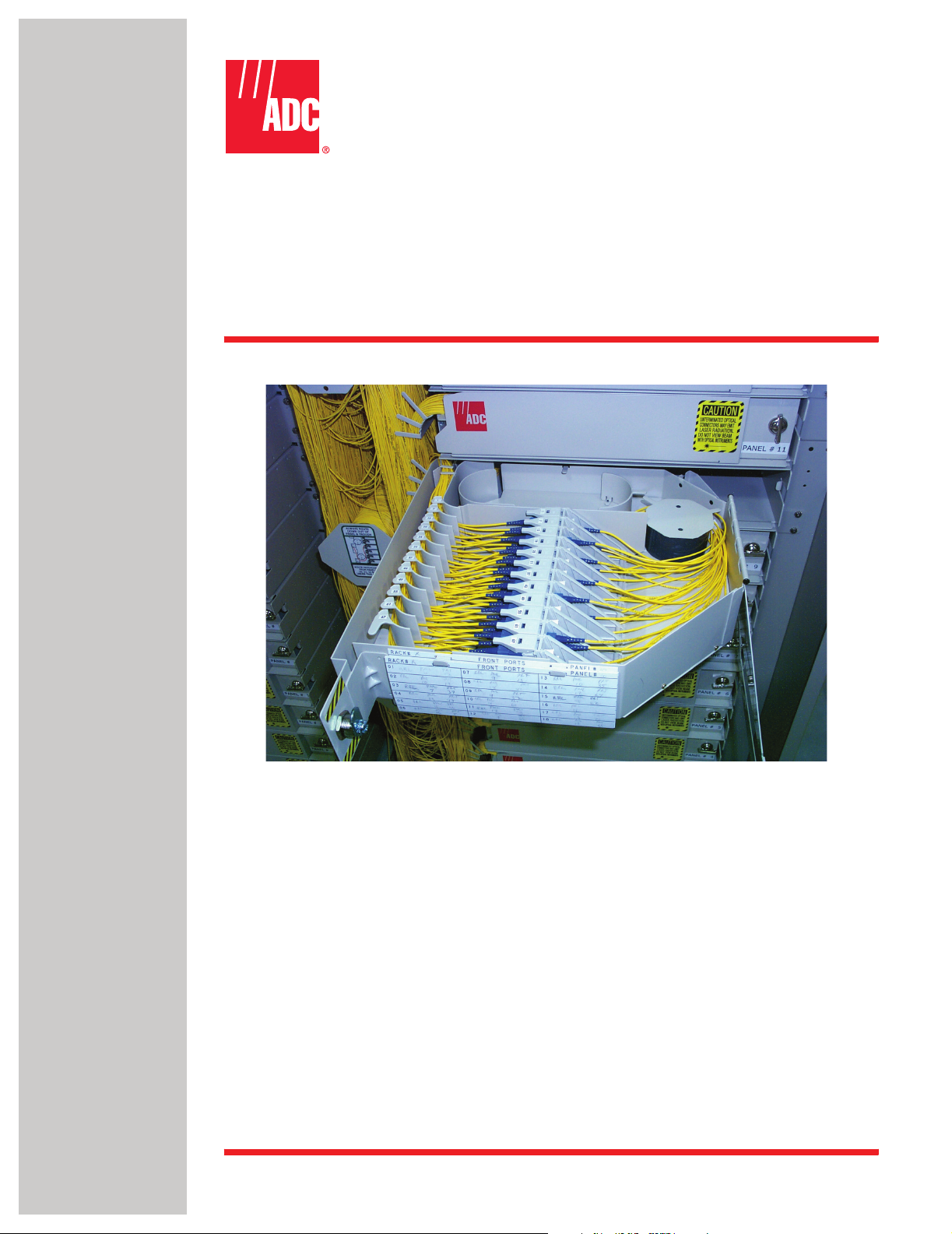
1.1 NG3 High-Density Fiber Distribution Frame System Overview
The 72-Position Standard Termination Panel, the 72-Position Termination and Splice Panel, and
the 12-position VAM Panel are components of the NG3 High-Density Fiber Distribution Frame
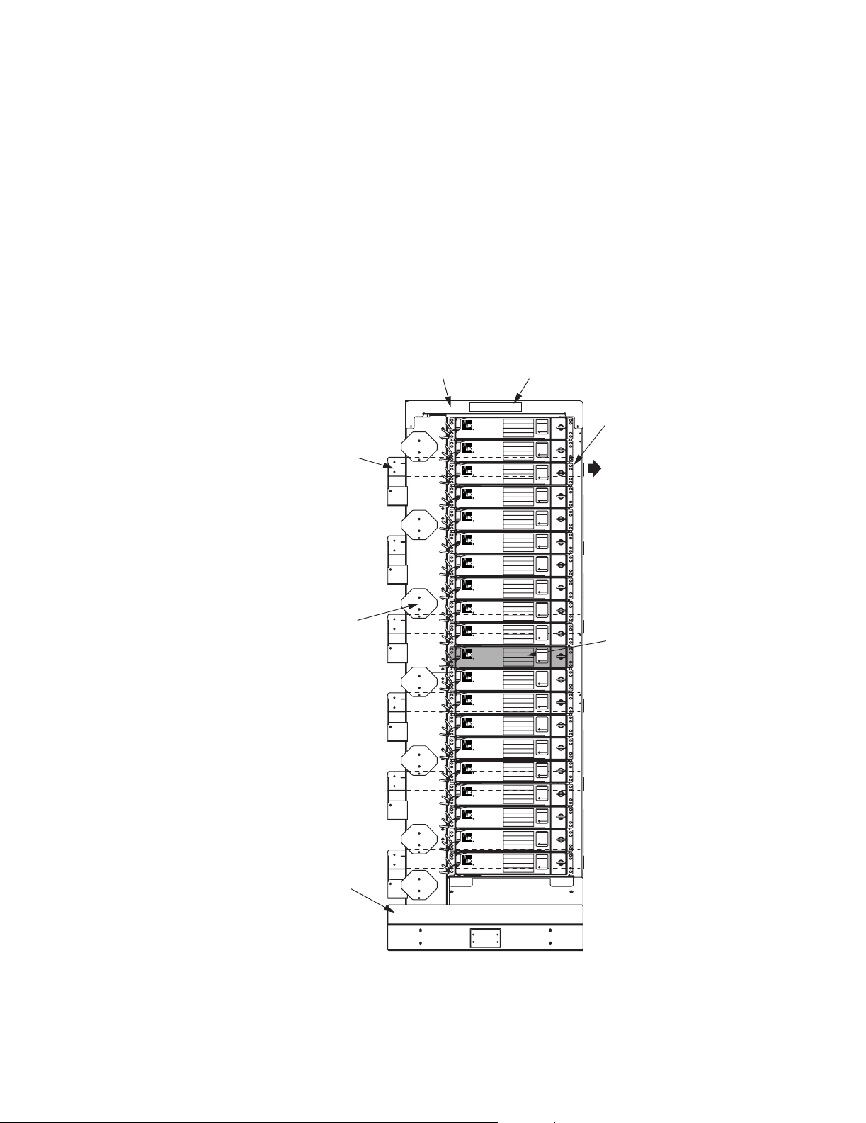
System. An example of a typical NG3 frame is shown in Figure 1.
ADCP-90-297 • Issue 7 • July 2006
FRONT-TO-REAR
TRANSITION
TROUGH
(6 PLACES)
SLACK
STORAGE
SPOOLS
(7 PLACES)
LOWER
TROUGH
UPPER
TROUGH
FRAME NUMBER
LABEL
CAUTION
XXXXXXXXXXXXX
XXXXXXXXXXXXX
XXXXXXXXXXXXX
XXXXXXXXXXXXX
XXXXXXXXXXX
CAUTION
XXXXXXXXXXXXX
XXXXXXXXXXXXX
XXXXXXXXXXXXX
XXXXXXXXXXXXX
XXXXXXXXXXX
CAUTION
XXXXXXXXXXXXX
XXXXXXXXXXXXX
XXXXXXXXXXXXX
XXXXXXXXXXXXX
XXXXXXXXXXX
CAUTION
XXXXXXXXXXXXX
XXXXXXXXXXXXX
XXXXXXXXXXXXX
XXXXXXXXXXXXX
XXXXXXXXXXX
CAUTION
XXXXXXXXXXXXX
XXXXXXXXXXXXX
XXXXXXXXXXXXX
XXXXXXXXXXXXX
XXXXXXXXXXX
CAUTION
XXXXXXXXXXXXX
XXXXXXXXXXXXX
XXXXXXXXXXXXX
XXXXXXXXXXXXX
XXXXXXXXXXX
CAUTION
XXXXXXXXXXXXX
XXXXXXXXXXXXX
XXXXXXXXXXXXX
XXXXXXXXXXXXX
XXXXXXXXXXX
CAUTION
XXXXXXXXXXXXX
XXXXXXXXXXXXX
XXXXXXXXXXXXX
XXXXXXXXXXXXX
XXXXXXXXXXX
CAUTION
XXXXXXXXXXXXX
XXXXXXXXXXXXX
XXXXXXXXXXXXX
XXXXXXXXXXXXX
XXXXXXXXXXX
CAUTION
XXXXXXXXXXXXX
XXXXXXXXXXXXX
XXXXXXXXXXXXX
XXXXXXXXXXXXX
XXXXXXXXXXX
CAUTION
XXXXXXXXXXXXX
XXXXXXXXXXXXX
XXXXXXXXXXXXX
XXXXXXXXXXXXX
XXXXXXXXXXX
CAUTION
XXXXXXXXXXXXX
XXXXXXXXXXXXX
XXXXXXXXXXXXX
XXXXXXXXXXXXX
XXXXXXXXXXX
CAUTION
XXXXXXXXXXXXX
XXXXXXXXXXXXX
XXXXXXXXXXXXX
XXXXXXXXXXXXX
XXXXXXXXXXX
CAUTION
XXXXXXXXXXXXX
XXXXXXXXXXXXX
XXXXXXXXXXXXX
XXXXXXXXXXXXX
XXXXXXXXXXX
CAUTION
XXXXXXXXXXXXX
XXXXXXXXXXXXX
XXXXXXXXXXXXX
XXXXXXXXXXXXX
XXXXXXXXXXX
CAUTION
XXXXXXXXXXXXX
XXXXXXXXXXXXX
XXXXXXXXXXXXX
XXXXXXXXXXXXX
XXXXXXXXXXX
CAUTION
XXXXXXXXXXXXX
XXXXXXXXXXXXX
XXXXXXXXXXXXX
XXXXXXXXXXXXX
XXXXXXXXXXX
CAUTION
XXXXXXXXXXXXX
XXXXXXXXXXXXX
XXXXXXXXXXXXX
XXXXXXXXXXXXX
XXXXXXXXXXX
CAUTION
XXXXXXXXXXXXX
XXXXXXXXXXXXX
XXXXXXXXXXXXX
XXXXXXXXXXXXX
XXXXXXXXXXX
CAUTION
XXXXXXXXXXXXX
XXXXXXXXXXXXX
XXXXXXXXXXXXX
XXXXXXXXXXXXX
XXXXXXXXXXX
REAR TROUGH
(NOT VISIBLE)
TO ADJACENT
REAR TROUGH
(6 PLACES)
NG3 TERMINATION
PANEL (TYPICAL)
NOTE: PANELS MAY BE
NUMBERED FROM 1 TO 20
STARTING WITH THE TOP
OR BOTTOM PANEL
18285-B
Figure 1. NG3 Panel on NG3 Frame
© 2006, ADC Telecommunications, Inc.
Page 1
Page 9

ADCP-90-297 • Issue 7 • July 2006
The NG3 frame and the optical panels mounted in the frame function as a distribution point for
fiber optic cables in a high density application. Each frame provides 20 mounting spaces for
NG3 panels with each panel providing up to 72 fiber ports. An NG3 frame also contains cable
management features including slack storage spools and cable troughs. A fully loaded frame
can support 1440 terminations using 2 mm patch cords.
1.2 NG3 72-Position Standard Termination Panel
The NG3 72-Position Standard Termination Panel is a rack-mount panel designed for mounting
on the NG3 frame. The panel has a hinged drawer that swings out to provide access to the
adapter packs within. The design of the panel allows for flexible deployment of all circuits
without a required termination plan or scheme.
The standard panel provides 72 adapter mounting positions (12 adapter packs, each with six
adapters). The adapters may be any of the standard single mode and multimode types including
SC, FC, and ST. For a complete list of adapter options, contact your ADC representative. The
primary components of the NG3 panel are shown in Figure 2 and consist of the following:
• Panel Chassis—The foundation structure of the panel. It is 17.18 inches (43.6 cm) wide
and 3.44 inches (8.7 cm) high. Each frame holds up to 20 panels of this size.
• Radius Limiters—Hold cables to a 1.5 inch minimum bend radius within the drawer to
protect the cable from being damaged by too severe a bend.
• Cable Spool—Holds cables to a 1.5 inch minimum bend radius within the drawer and
keeps cables in position when the drawer is opened.
• Mounting Tabs—Used to fasten the panel on the NG3 rack.
• Drawer Cover—Protects cables when closed and provides access to adapters when open.
The cover is cut out above the adapter packs so as not to press on them when closed. The
cover, when open, acts as a stop to prevent the drawer from being accidentally closed.
• Designation Cards—Provide two square inches each of port designation space for all 72
ports, front and rear.
• Adapter Packs—Separately mountable assemblies, each consisting of a housing and six
adapters. The adapter packs swing up individually from their home position, providing full
access to front and rear terminations.
• Door Latch—Holds the door in a closed position, can be replaced with a key lock for
locations where security is a concern.
• Hinged Drawer—Swings out from within the panel to the position shown.
• Radius Limiters—Guide patch cords routed out of panel to front of frame.
The adapter pack ports are numbered in ascending numeric order from top to bottom in each
individual pack and from rear to front among the adapter packs. Port number 1 is at the top of
the adapter pack furthest to the rear of the drawer and port number 72 is at the bottom of the
adapter pack furthest to the front. Each of the four designation cards at the front of the drawer
have room for 18 port designations.
Page 2
© 2006, ADC Telecommunications, Inc.
Page 10
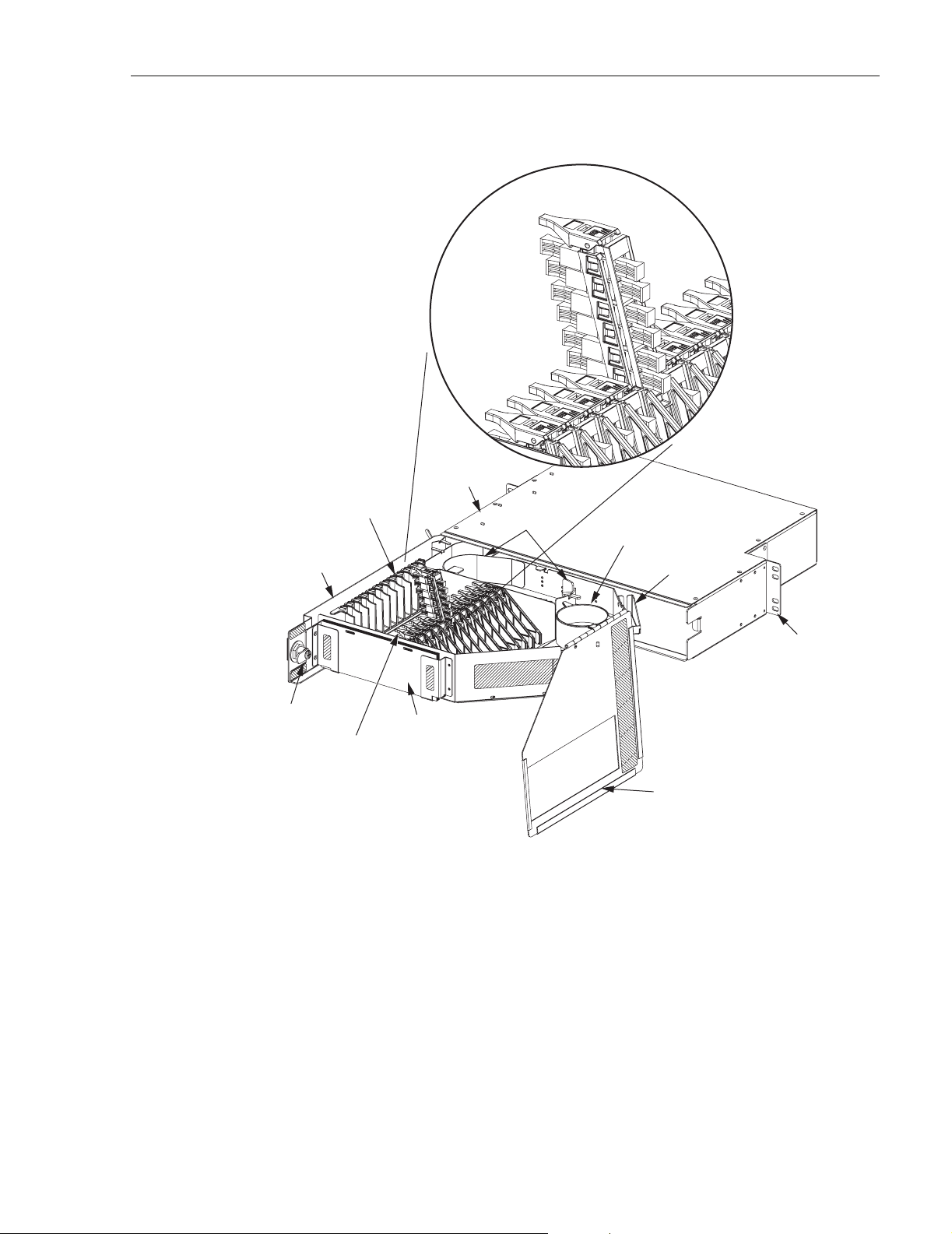
HINGED
DRAWER
RADIUS
LIMITERS
ADAPTER
POSITION
PANEL
CHASSIS
PAC K
IN OPEN
LIMITERS
ADCP-90-297 • Issue 7 • July 2006
RADIUS
CABLE
SPOOL
FIBER
TRANSPORT
18543-B
MOUNTING
TABS
(1 EACH SIDE)
DOOR LATCH
(OR KEY LOCK)
ADAPTER
PACKS
DESIGNATION
CARDS
DRAWER
COVER
Figure 2. NG3 72-Position Standard Termination Panel
1.2.1 NG3 Standard Termination Panel Options
The NG3 standard termination panel may be ordered in either of two configurations:
• Unterminated—Panel is equipped with adapter packs only.
• Preterminated—Panel is equipped with adapter packs and an IFC cable that is pre-
installed in the panel. The stub end of the cable is coiled up or placed on a spool.
© 2006, ADC Telecommunications, Inc.
Page 3
Page 11

ADCP-90-297 • Issue 7 • July 2006
1.2.2 NG3 Standard Termination Panel Accessories
The following accessories are available for use with the NG3 standard termination panel:
• Cable Clamp Kit—provides a clamp and other hardware required for securing an IFC or
OSP cable to the rear side of the NG3 panel.
• IFC Cable Assemblies—are available with single mode or multimode fiber in specified
lengths and with specified connectors.
• Patch Cords—are available with specified connectors in standard lengths of 3.0, 5.0, 6.0,
7.0, 8.0, 9.0, 10.0, and 12.0 meters.
• Adapter Packs—are available separately with specified adapters, and can be used either
as replacements for existing adapter packs. The adapters may be any of the standard single
mode and multimode types, including SC, FC, and ST. For a current list of adapter
options, contact your ADC representative.
• Inline Attenuators—are installed between a connector and an adapter to protect
equipment by attenuating optical signals to acceptable levels. ADC inline attenuators are
fused attenuators providing exceptional optical performance.
• TracerLight Connector Identification System—offers a quick and accurate method of
identifying the termination point of optical patch cords. Each end of a TracerLight patch
cord features a flashing light source allowing technicians to visually trace individual patch
cords from one end to the other without pulling or affecting the patch cord. Use of a
TracerLight system minimizes the risk of taking the incorrect fiber out of service,
improving system turn-up speed and accuracy. TracerLight patch cords meet all
performance criteria of standard ADC patch cords.
1.3 NG3 72-Position Termination and Splice Panel
The NG3 72-Position Termination and Splice Panel is similar to the standard termination panel
described in Section 1.2 but includes additional features that allow a ribbon-type 72-fiber IFC
cable to be routed to the panel and spliced to a pre-installed connectorized cable assembly
within the panel. The termination and splice panel mounts in the NG3 rack and has a hinged
drawer that swings out to provide access to the adapter packs and splice tray. The termination
and splice panel is primarily used in “tie panel” applications.
The termination and splice panel provides 72 adapter mounting positions (12 adapter packs,
each with six adapters) and one splice tray for ribbon-type fusion splices. The same adapter
types offered with the standard termination panel are available. The termination and splice panel
is equipped with a ribbon-type connectorized cable assembly which is pre-installed in the panel
drawer and ready for splicing. The additional features and equipment provided with the
termination and splice panel are shown in Figure 3 and described as follows:
• Cable Clamp–Used to secure the ribbon-type IFC cable to the rear side of the panel.
Includes cable clamps, grommet, cover plate, and screws.
• Ribbon Cable Blocking Kit–Separates and protects the fiber ribbons at the cable break-
out point. Includes a protective oval tube assembly for the six 12-fiber ribbons, a fanout
base with cover, cover screws, cable ties, and tape. Instructions for kit assembly are
included.
Page 4
© 2006, ADC Telecommunications, Inc.
Page 12
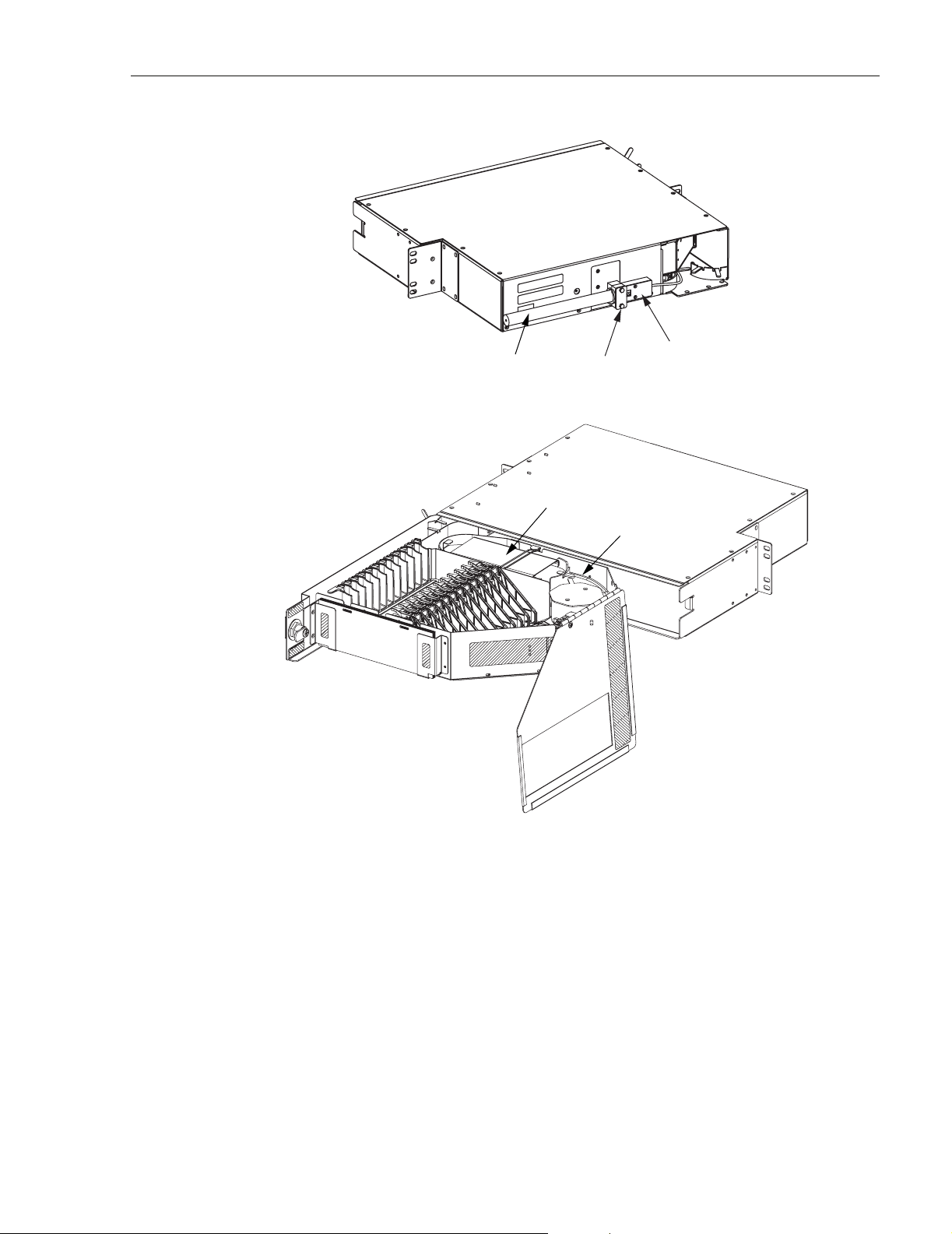
REAR VIEW
IFC CABLE
ROUTED TO PANEL
CABLE
CLAMP KIT
ADCP-90-297 • Issue 7 • July 2006
RIBBON
BLOCKING
KIT
SPLICE TRAY
FRONT VIEW
RIBBON-TYPE
CONNECTORIZED
CABLE ASSEMBLY
19993-A
Figure 3. NG3 72-Position Termination and Splice Panel
• Splice Tray–An all metal tray that protects and stores the completed splices and bare fiber
ribbons. Includes a protective cover and two 6-position fusion-type ribbon splice chips for
holding the splices.
• Ribbon-Type Connectorized Cable Assembly–A ribbon-type 72-fiber IFC cable
assembly terminated with customer-specified connectors. The cable assembly is preinstalled in the drawer and the connectors are mated with the adapter packs. At the cable
fanout point, the cable assembly is broken-out into six 12-fiber ribbons which are placed
in protective tubing and routed to the splice tray.
© 2006, ADC Telecommunications, Inc.
Page 5
Page 13

ADCP-90-297 • Issue 7 • July 2006
1.4 NG3 12-Position Value Added Module Panel
The NG3 12-Position Value Added Module (VAM) Panel is a rack-mount panel designed for
mounting on the NG3 rack. The panel has a hinged drawer that swings out to provide access to
the VAM’s within. The VAM panel, shown in Figure 4, allows optical splitter or Wavelength
Division Multiplexing (WDM) functionality to be incorporated into specified optical circuits at
the NG3 frame. Optical splitters are used to divide the optical signal for distribution to multiple
ports in order to provide test, access, and monitoring capability. WDM’s are used to increase
transmission capacity, combine separate services on an existing network, and to provide nonintrusive testing.
The following basic VAM types are available:
• Splitter–Distributes the optical signal to multiple circuits
• Monitor–Provides a test or access point in an optical circuit
• Wavelength Division Multiplexer–Allows transmission of two optical wavelengths in the
same direction on the same fiber (unidirectional) or transmission of two optical
wavelengths in the opposite direction on the same fiber (bidirectional)
PATCH CORD
STORAGE
VALUE ADDED MODULE
ASSEMBLIES (12)
Figure 4. NG3 Value Added Module Panel
19987-B
The VAM panel provides twelve micro VAM assembly mounting positions. The VAM
assemblies must be ordered separately and installed in the panel on an as needed basis. Each
VAM assembly, shown in Figure 5, provides a maximum of six front access input/output
adapter ports. The same adapter types offered with the termination panel and termination/splice
panel are also available with the VAM assembly.
Page 6
© 2006, ADC Telecommunications, Inc.
Page 14
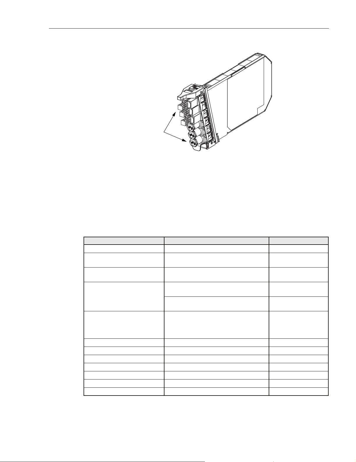
FRONT
ACCESS
ADAPTERS
1.5 Specifications and Dimensions
ADCP-90-297 • Issue 7 • July 2006
19986-B
Figure 5. Typical Micro Value Added Module
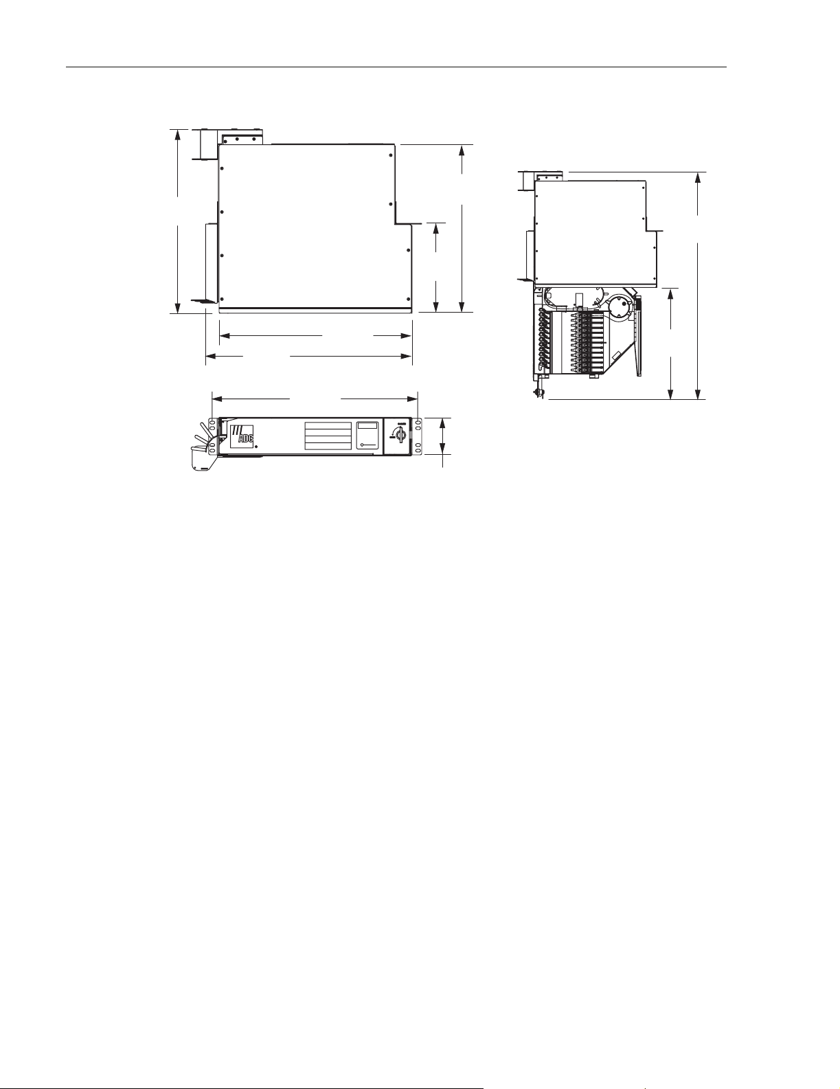
Tab le 1 provides specifications for the various NG3 Frame System panels. The dimensions of a
typical panel (with the drawer open and closed) are shown in Figure 6.
Table 1. NG3 Frame System Panel Specifications
PARAMETER SPECIFICATION REMARKS
Physical
Number of terminations or
VAM ports (maximum)
Number of adapter packs or
VA M ’s ( m a x i m um )
Dimensions (H x W x D) 3.44 x 18.31 x 16.38 in.
Connector and adapter types
available
Environment
Temperature
Operating –40° C to 65° C (–40° F to 149° F)
Storage –40° C to 85° C (–40° F to 185° F)
Relative humidity
Operating Up to 80% No condensation
Storage Up to 95% No condensation
72
12
(8.7 x 46.6 x 41.6 cm)
3.44 x 18.31 x 30.57 in.
(8.7 x 46.6 x 77.6 cm)
Available in most standard types including
singlemode PCST, PCFC, 8° SC/APC, 8°
FC/APC, 8° E-2000/APC, and duplex 8°
SC/APC, and multimode SC, FC, and ST
With hinged drawer
closed
With hinged drawer
open
Contact ADC for connector recommendations and performance
information.
© 2006, ADC Telecommunications, Inc.
Page 7
Page 15
ADCP-90-297 • Issue 7 • July 2006
16.34 IN.
(41.5 CM)
TOP VIEW
15.06 IN.
(38.3 CM)
32.01 IN.
(81.3 CM)
8.00 IN.
(20.3 CM)
18.37 IN.
(46.6 CM)
2 NG3 PANEL INSTALLATION
NG3 panel installation includes unpacking and inspecting the panel and any accessories,
mounting the panel on the frame, installing the panel label, and installing VAM’s. Installation of
an NG3 panel into the frame should take less than ten minutes.
ADC does not recommend mounting NG3 panels in any frame except the NG3 High Density
Fiber Distribution Frame. When splicing or using test equipment, work on a secure surface at a
convenient work level. Do not use the NG3 panel to support splice or test equipment.
17.25 IN.
(43.8 CM)
18.32 IN.
(46.5 CM)
FRONT VIEW
CAUTION
XXXXXXXXXXXXX
XXXXXXXXXXXXX
XXXXXXXXXXXXX
XXXXXXXXXXXXX
XXXXXXXXXXX
XXXXXXXXXXX
XXXXXXXXXXX
3.44 IN.
(8.7 CM)
TOP VIEW WITH
SWING-OUT DRAWER
OPEN 90 DEGREES
Figure 6. Typical NG3 Frame System Panel Dimensions
15.67 IN.
(39.8 CM)
20260-A
2.1 Unpacking and Inspection
Use the following procedure to unpack and inspect the NG3 panel:
1. Inspect the shipping carton for signs of damage and note any evidence of rough handling.
2. Open the carton and carefully unpack each item from the protective packing material.
3. If damage is detected or if parts are missing, file a claim with the commercial carrier. Save
the damaged carton for inspection by the carrier.
4. Contact ADC (see Section 7 at the end of this manual) for an RMA (Return Material
Authorization) and to reorder if replacement is required.
Page 8
© 2006, ADC Telecommunications, Inc.
Page 16
2.2 Mounting the NG3 Panel on the Frame
Use the following procedure to mount any NG3 panel on the NG3 frame:
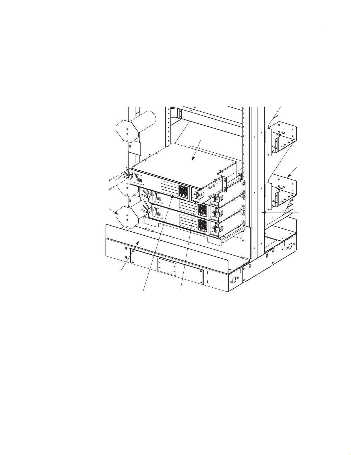
1. Determine where the panel will be located on the frame.
2. Align the mounting holes in the panel with the mounting holes in the frame as shown in
Figure 7.
NG3
PANEL
ADCP-90-297 • Issue 7 • July 2006
REAR
TROUGH
SLACK
STORAGE
SPOOL
LOWER
TROUGH
GENERAL
PURPOSE
LABEL
AFFIX PANEL NUMBER
LABEL HERE. LABEL
SHEET PROVIDED
WITH FRAME.
18297-B
FRAME
Figure 7. Mounting the Panel on the Frame
3. Secure the panel to the frame using the four screws and washers provided with the panel.
4. Record the panel number and/or connector type on the general purpose label provided on
the front of the panel.
© 2006, ADC Telecommunications, Inc.
Page 9
Page 17
ADCP-90-297 • Issue 7 • July 2006
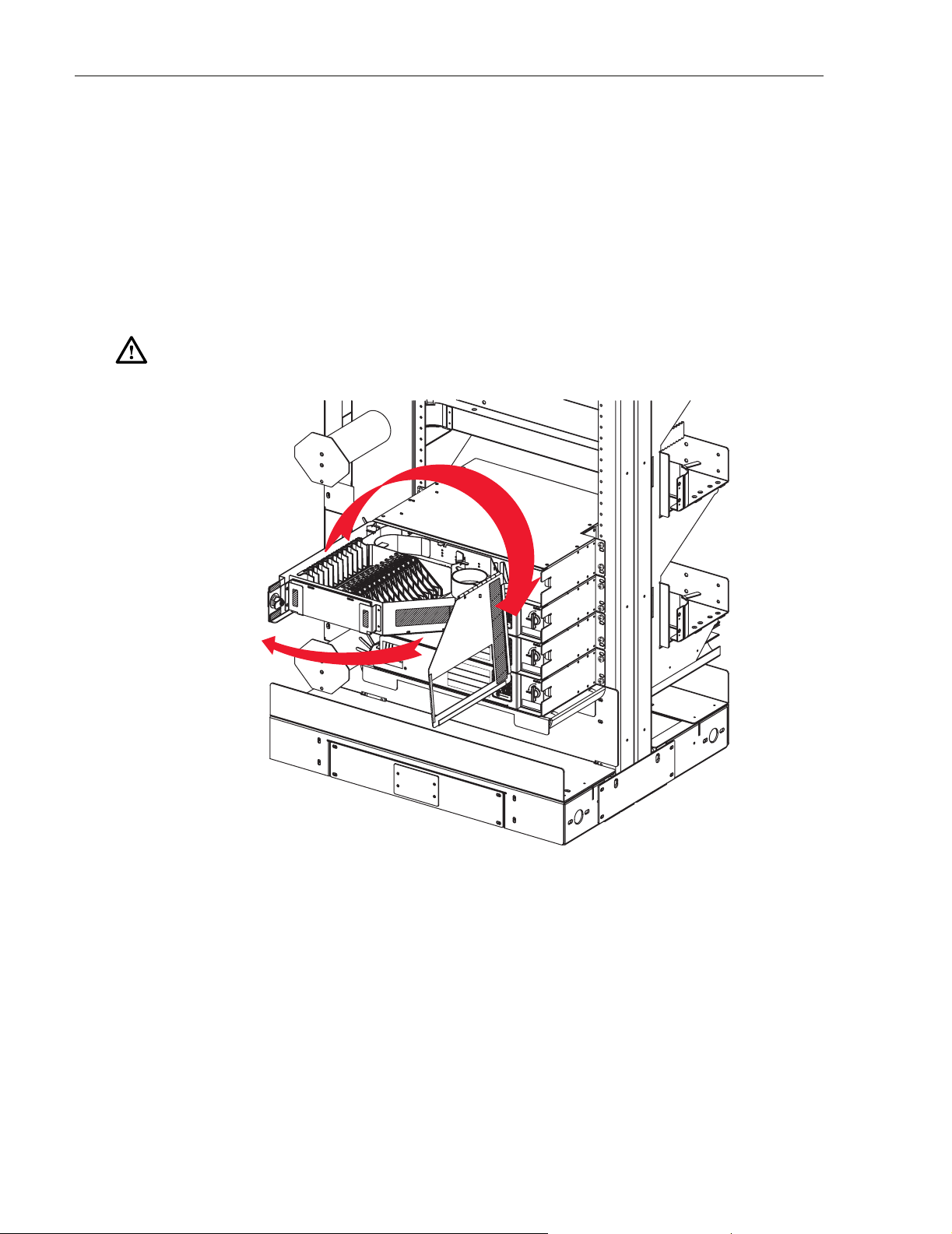
2.3 Opening the NG3 Panel
Use the following procedure to open any NG3 panel:
1. Rotate the door latch 90º counterclockwise.
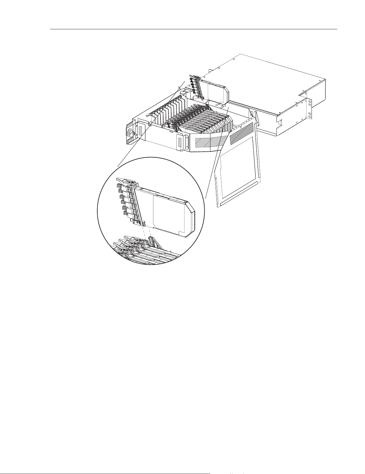
2. Swing out the drawer as shown in Figure 8.
3. When the hinged drawer comes to rest in a position 90º out from the panel chassis, rotate
the top cover up and to the right. Allow the cover to hang down beside the drawer when
accessing the adapter packs or routing fibers within the drawer.
Caution: Placing a load in excess of 20 pounds onto an open drawer will result in
misalignment or damage to the drawer.
Figure 8. Opening the Hinged Drawer
2.4 Installing Micro Value Added Modules
To prevent damage during shipment, all NG3 VAM panels are shipped without the micro VAMs
installed in the VAM panel mounting slots. Use the following procedure to install the micro
VAMs in the VAM panel:
1. Open the VAM panel as described in Subsection 2.3
2. Position the micro VAM about the selected mounting position as shown in Figure 9.
3. Slide the VAM down into the mounting slot.
Page 10
© 2006, ADC Telecommunications, Inc.
18298-C
Page 18
VALUE ADDED
MODULE ASSEMBLY
ADCP-90-297 • Issue 7 • July 2006
20288-A
Figure 9. Installing a Micro VAM
3 IFC CABLE ROUTING AND INSTALLATION
This section provides instructions for routing an IFC cable through an NG3 frame and installing
the cable in the appropriate NG3 panel. If the IFC cable is pre-installed in the panel, disregard
subsections 3.2 through 3.4. IFC cables may be of stranded or ribbon type construction.
3.1 General IFC Cable Routing Guidelines–All Panel Types
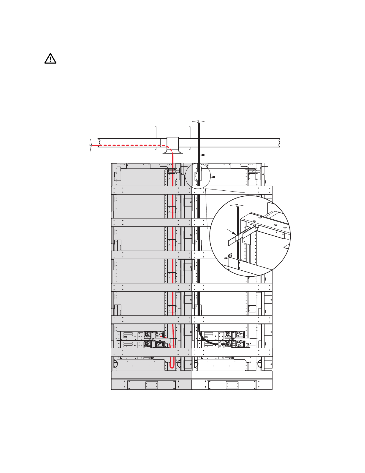
IFC cables are routed to the rear side of the frame from either above or below the NG3 panel.
Each IFC cable is routed vertically up or down the left rear side of the frame to the designated
panel as shown in Figure 10. The IFC cable is then routed horizontally from left to right to the
rear of the designated panel and into the opening on the right rear side of the panel. A clamp
secures the IFC cable to the rear side of the panel. The cable should also be secured to the frame
using wax lacing tied to the tie down bars located on the left rear side of the frame.
© 2006, ADC Telecommunications, Inc.
Page 11
Page 19
ADCP-90-297 • Issue 7 • July 2006
Caution: Applying excessive tension on lacing cables can cause physical damage and
attenuation of optical fibers.
The cable shall maintain a minimum bend radius of 1.5 inches or ten times the cable outside
diameter, which ever is greater, inside the cable raceways and within the NG3 frame. Secure the
cable to the overhead raceway per local practice. ADC does not recommend storing slack cable
on the NG3 frame. If cable storage is required, follow local practice.
IFC CABLE
IFC
TIE-DOWN
LOCATION
REAR VIEW
LACING
18304-D
Page 12
© 2006, ADC Telecommunications, Inc.
Figure 10. IFC Cable Routing on Rear of Frame
Page 20

3.2 Standard Termination Panel IFC Cable Installation
Use the following procedure to install a connectorized IFC cable in an unterminated (adapters
only) standard termination panel. A conversion kit (NG3-ACCIFCKIT) is required.
Note: This procedure is most efficiently done by two people, with one person at the front
of the panel and the other person at the rear.
1. Break out the cable according to the dimensions provided in Figure 11 (stranded cable) or
Figure 12 (ribbon cable). For ribbon cable, install protective tubing, fanouts, and upjackets
in the locations shown.
BREAKOUT LENGTH
65.0 IN. (165.1 CM)
+0.0 IN./-6.0 IN.
(+0.0 CM/-15.2 CM)
FANOUT LENGTH
37.0 IN. (93.9 CM)
+0.0 IN./-6.0 IN.
(+0.0 CM/-15.2 CM)
2.0 IN.
(5.1 CM)
ADCP-90-297 • Issue 7 • July 2006
IFC
CABLE
19786-B
CONNECTORS
SUBUNIT
DESIGNATION
LABEL
HEATSHRINK
6.0 IN. (15.2 CM)
CLAMP
Figure 11. Breakout Cable Dimensions for Stranded Cable Routed to Standard Termination Panel
CLAMP
BREAKOUT LENGTH
65.0 IN. (165.1 CM)
+0.0 IN./-6.0 IN.
(+0.0 CM/-15.2 CM)
FLARE
TUBE
INDIVIDUAL
PROTECTIVE
TUBING
SUBUNIT
DESIGNATION
LABEL
CLAMP POSITION
69.0 IN. (175.3 CM)
+0.0 IN./-6.0 IN.
(+0.0 CM/-15.2 CM)
FANOUT LENGTH
FANOUT
INDIVIDUAL
UPJACKETED
FIBER
38.0 IN. (96.5 CM)
+0.0 IN./-6.0 IN.
(+0.0 CM/-15.2 CM)
CONNECTORS
19787-B
Figure 12. Breakout Cable Dimensions for Ribbon Cable Routed to Standard Termination Panel
© 2006, ADC Telecommunications, Inc.
Page 13
Page 21
ADCP-90-297 • Issue 7 • July 2006
2. Locate the panel where the cable will be installed and position one person at the front of
the panel and another person at the rear.
3. At the front of panel, fully open the hinged drawer (refer to Subsection 2.3).
Caution: Placing a load in excess of 20 pounds onto an open drawer will result in
misalignment or damage to the drawer.
4. At the rear of the panel, insert the bundled connector end of the cable into the panel rear
entry hole, as shown in Figure 13, and slide it through to the front.
CLAMP POINT
SLIDE BUNDLED
FIBERS IN
FROM REAR
PANEL SHOWN
WITH TOP
REMOVED FOR
CLARITY
5. At the front of the panel, lift the cable up over the top edge of the hinged drawer and move
the cable to the cable entry hole on the left side of the drawer, as shown in Figure 14.
Page 14
© 2006, ADC Telecommunications, Inc.
20287-A
Figure 13. Routing IFC Cable Into Standard Termination Panel
Page 22
ADCP-90-297 • Issue 7 • July 2006
ROUTE FIBERS UNDER
PROTECTOR PLATE
LIFT CABLE
FIBERS
INTO CABLE
ENTRY HOLE
MOVE BUNDLED
FIBERS TO THE LEFT
PANEL SHOWN
WITH TOP
REMOVED FOR
CLARITY
20289-B
Figure 14. Positioning IFC Cable Within Standard Termination Panel
6. At the rear of the panel, clamp the cable to the panel using a cable clamp kit. The
components of the cable clamp kit are shown in Figure 15.
Note: Position the cable clamp on the cable at the point indicated in the cable breakout
diagrams. For ribbon cable, refer to Figure 11. For stranded cable, refer to Figure 12.
© 2006, ADC Telecommunications, Inc.
Page 15
Page 23
ADCP-90-297 • Issue 7 • July 2006
GROMMET
(IF NEEDED)
18431-B
PLATE
HEX
MOUNTING
SCREWS
YOKES
MOUNTING
HOLES
Figure 15. Clamping Cable to Standard Termination Panel
7. Route the cable fibers within the drawer as shown in Figure 16 (stranded cable) or
Figure 17 (ribbon cable).
8. Locate the assigned adapter and lift up the adapter pack. (refer to Subsection 5.1).
9. Remove the dust caps from the connectors and the rear side of the adapters and then insert
each connector into the appropriate adapter.
Note: Clean and inspect the connectors and adapters before mating them. For guidelines,
refer to Subsection 5.3.
Danger: Infrared radiation is invisible and can seriously damage the retina of the eye. Do not
look into the ends of any optical fiber connector or adapter. Exposure to invisible laser
radiation may result. An optical power meter should be used to verify active fibers. A protective
cap or hood MUST be immediately placed over any radiating adapter or optical fiber connector
to avoid the potential of dangerous amounts of radiation exposure. This practice also prevents
dirt particles from entering the adapter or connector.
Page 16
© 2006, ADC Telecommunications, Inc.
Page 24

ADCP-90-297 • Issue 7 • July 2006
10. Secure the cable to the drawer at the cable retention area using the O-ring provided with
the panel. Refer to Figure 16 or Figure 17 for details.
11. Return the adapter pack to its home position.
12. Continue routing and connecting any remaining connectors on the same cable.
13. When done, close the panel (refer to Subsection 5.5).
PANEL SHOWN
WITH TOP
REMOVED FOR
CLARITY
IFC CABLE
SLACK LOOP
CABLE
RETENTION
AREA
20290-A
CABLES SHOULD BE
LOOSE IN DRAWER.
FIBERS SHOULD NOT
BE TIGHT WHEN SAP
Figure 16. Stranded Cable Routing Within Standard Termination Panel
IS RAISED.
© 2006, ADC Telecommunications, Inc.
Page 17
Page 25

ADCP-90-297 • Issue 7 • July 2006
PANEL SHOWN
WITH TOP
REMOVED FOR
CLARITY
SLACK LOOPS
FANOUT
20291-A
CABLES SHOULD BE
LOOSE IN DRAWER.
FIBERS SHOULD NOT
BE TIGHT WHEN SAP
IS RAISED.
Figure 17. Ribbon Cable Routing Within Standard Termination Panel
Page 18
© 2006, ADC Telecommunications, Inc.
Page 26

3.3 Termination and Splice Panel IFC Cable Installation and Splicing
The Termination and Splice Panel may be used to splice an unterminated 72-fiber ribbon-type
IFC cable to a connectorized cable assembly installed within the panel. Use the following
procedure to secure the IFC cable to the panel and to splice the IFC cable to the installed cable
assembly:
Note: This procedure is most efficiently done by two people, with one person at the front
of the panel and the other person at the rear.
1. Break out the cable and install the blocking kit (provided with panel) as shown in
Figure 18. Expose at least 156 inches (396 CM) of bare ribbon when assembling the
blocking kit. Refer to the Ribbon Blocking Kit Installation Instructions (ADCP-93-305)
for the kit assembly details.
ADCP-90-297 • Issue 7 • July 2006
EXPOSE AT LEAST
156 INCHES (396 CM)
WHEN ASSEMBLING
PLACE ALL SIX FIBER
RIBBONS WITHIN TUBING
OF BARE RIBBON
BLOCKING KIT
115 INCHES
(291 CM)
20209-A
Figure 18. Ribbon Blocking Kit Assembly
2. Locate the panel where the cable will be installed and position one person at the front of
the panel and another person at the rear.
3. At the front of panel, fully open the hinged drawer (refer to Subsection 2.3).
Caution: Placing a load in excess of 20 pounds onto an open drawer will result in
misalignment or damage to the drawer.
4. At the rear of the panel, insert the ribbon tube into the panel rear entry hole, as shown in
Figure 19, and slide it through to the front.
© 2006, ADC Telecommunications, Inc.
Page 19
Page 27

ADCP-90-297 • Issue 7 • July 2006
CLAMP POINT
PANEL SHOWN
WITH TOP
REMOVED FOR
CLARITY
SLIDE RIBBON
TUBE IN FROM REAR
20210-A
Figure 19. Routing Ribbon Tube into Termination and Splice Panel
5. At the front of the panel, lift the ribbon tube up over the top edge of the hinged drawer and
move the tube to the cable entry hole on the left side of the drawer, as shown in Figure 20.
Page 20
© 2006, ADC Telecommunications, Inc.
Page 28

ROUTE RIBBON
TUBE UNDER
PROTECTOR PLATE
LIFT RIBBON
TUBE INTO CABLE
ENTRY HOLE
MOVE RIBBON
TUBE TO LEFT
ADCP-90-297 • Issue 7 • July 2006
PANEL SHOWN
WITH TOP
REMOVED FOR
CLARITY
20211-B
Figure 20. Positioning Ribbon Tube Within Termination and Splice Panel
6. At the rear of the panel, clamp the cable to the panel using the cable clamp kit provided.
The components of the cable clamp kit are shown in Figure 21.
© 2006, ADC Telecommunications, Inc.
Page 21
Page 29

ADCP-90-297 • Issue 7 • July 2006
GROMMET
(IF NEEDED)
19991-C
YOKES
PLATE
MOUNTING
HOLES
HEX
MOUNTING
SCREWS
RIBBON
BLOCKING
KIT
Figure 21. Clamping IFC Ribbon Cable to Termination and Splice Panel
7. Route the ribbon tube once around and under the splice tray as shown in Figure 22.
ROUTE RIBBON
TUBE UNDER
PROTECTOR PLATE
PANEL SHOWN
WITH TOP
REMOVED FOR
CLARITY
Page 22
© 2006, ADC Telecommunications, Inc.
20212-A
Figure 22. Routing Ribbon Tube Around and Under Splice Tray
Page 30

ADCP-90-297 • Issue 7 • July 2006
8. Remove the splice tray cover and then secure the ribbon tube to the splice tray at the point
indicated in Figure 23. Use wax lacing to attach the ribbon tube to the splice tray.
SECURE TUBING
TO TRAY USING
WAX LACING
19990-A
Figure 23. Securing Ribbon Tube To The Splice Tray
9. Remove the splice tray from the drawer and uncoil the attached optical fibers from the
slack storage area around and under the splice tray.
10. Splice the IFC cable fibers to the cable assembly fibers following local splicing practice.
Two ribbon-type splice chips are attached to the bottom of the splice tray.
Note: ADC recommends that all splicing be done per Telecordia GR-1095-CORE and
GR-765 requirements.
11. When splicing is completed, re-install the splice tray cover on the splice tray and coil up
the excess slack from the attached optical fibers in the slack storage area.
12. Place the splice tray back in the panel and then close the drawer (refer to Subsection 5.5)
3.4 VAM Panel IFC Cable Installation
The VAM panel allows optical splitter or wavelength division multiplexing (WDM)
functionality to be incorporated into specified optical circuits at the NG3 frame. Use the
following procedure to install a connectorized stranded-type IFC cable in a VAM panel:
1. Break out the IFC cable according to the dimension shown in Figure 24.
2. Locate the panel where the cable will be installed and position one person at the front of
the panel and another person at the rear.
3. At the front of panel, fully open the hinged drawer (refer to Subsection 2.3).
Caution: Placing a load in excess of 20 pounds onto an open drawer will result in
misalignment or damage to the drawer.
4. At the rear of the panel, insert the bundled connector end of the cable into the panel rear
entry hole, as shown in Figure 25, and slide it through to the front.
© 2006, ADC Telecommunications, Inc.
Page 23
Page 31

ADCP-90-297 • Issue 7 • July 2006
CONNECTORS
BREAKOUT LENGTH
48.0 IN. (121.9 CM)
+0.0 IN./-3.0 IN.
(+0.0 CM/-7.6 CM)
2.0 IN.
(5.1 CM)
HEATSHRINK
6.0 IN. (15.2 CM)
Figure 24. Breakout Dimension for Stranded IFC Cable Routed to VAM Panel
CLAMP POINT
PANEL SHOWN
WITH TOP
SLIDE FIBERS IN
FROM REAR
REMOVED FOR
CLARITY
MULTI-FIBER IFC CABLE
2 MM MAX.
OUTSIDE DIAMETER
FOR SUBUNITS
CLAMP
20213-B
Page 24
© 2006, ADC Telecommunications, Inc.
20278-A
Figure 25. Routing IFC Cable Into VAM Panel
Page 32

ADCP-90-297 • Issue 7 • July 2006
5. At the front of the panel, lift the cable up over the top edge of the hinged drawer and move
the cable to the cable entry hole on the left side of the drawer, as shown in Figure 26.
PANEL SHOWN
ROUTE FIBERS UNDER
PROTECTOR PLATE
LIFT FIBERS INTO
CABLE ENTRY HOLE
MOVE FIBERS
TO LEFT
WITH TOP
REMOVED FOR
CLARITY
20279-B
Figure 26. Positioning IFC Cable Within VAM Panel
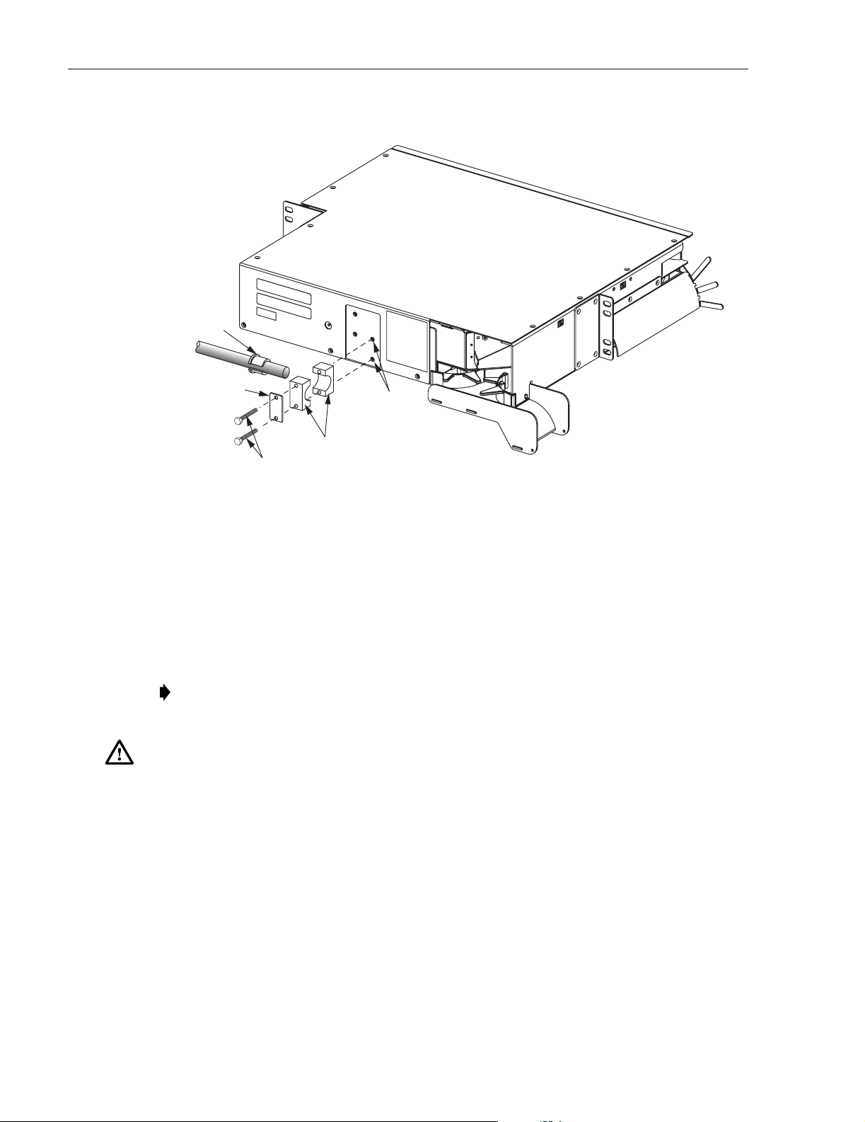
6. At the rear of the panel, clamp the cable to the panel using a cable clamp kit. The
components of the cable clamp kit are shown in Figure 27.
© 2006, ADC Telecommunications, Inc.
Page 25
Page 33

ADCP-90-297 • Issue 7 • July 2006
GROMMET
(IF NEEDED)
18431-B
PLATE
YOKES
HEX
MOUNTING
SCREWS
MOUNTING
HOLES
Figure 27. Clamping IFC Cable To VAM Panel
7. Route the cable fibers within the drawer as shown in Figure 28.
8. Locate the assigned VAM and lift it up to access the adapters (refer to Subsection 5.2).
9. Remove the dust caps from the connectors and the VAM adapters and then insert each
connector into the appropriate adapter.
Note: Clean and inspect the connectors and adapters before mating them. For guidelines,
refer to Subsection 5.3.
Danger: Infrared radiation is invisible and can seriously damage the retina of the eye. Do not
look into the ends of any optical fiber connector or adapter. Exposure to invisible laser
radiation may result. An optical power meter should be used to verify active fibers. A protective
cap or hood MUST be immediately placed over any radiating adapter or optical fiber connector
to avoid the potential of dangerous amounts of radiation exposure. This practice also prevents
dirt particles from entering the adapter or connector.
Page 26
© 2006, ADC Telecommunications, Inc.
Page 34

ADCP-90-297 • Issue 7 • July 2006
10. Store the excess slack by routing the cable fibers around the radius limiter provided (see
Figure 28).
11. Return the VAM to its home position.
12. Continue routing and connecting any remaining connectors on the same cable.
13. When done, close the panel (refer to Subsection 5.5).
PANEL SHOWN
ROUTE FIBERS
UNDER
PROTECTOR PLATE
IFC CABLE
SLACK LOOPS
WITH TOP
REMOVED FOR
CLARITY
20286-A
Figure 28. IFC Cable Installed In VAM Panel
© 2006, ADC Telecommunications, Inc.
Page 27
Page 35

ADCP-90-297 • Issue 7 • July 2006
3.5 Standard Termination Panel Breakout Cable Installation
Use the following procedure to install a connectorized breakout cable in an unterminated
(adapters only) standard termination panel. A conversion kit (NG3-ACCIFCKIT) is required.
Note: This procedure is most efficiently done by two people, with one person at the front
of the panel and the other person at the rear.
1. Break out the cable according to the dimensions provided in Figure 29.
BREAKOUT LENGTH
65.0 IN. (165.1 CM)
+0.0 IN./-6.0 IN.
(+0.0 CM/-15.2 CM)
CONNECTORS
HEATSHRINK
6.0 IN. (15.2 CM)
2.0 IN.
(5.1 CM)
MULTI-FIBER IFC CABLE
2 MM MAX.
OUTSIDE DIAMETER
FOR SUBUNITS
21430-A
CLAMP
Figure 29. Breakout Dimensions for Breakout Cable Routed to Standard Termination Panel
2. Locate the panel where the cable will be installed and position one person at the front of
the panel and another person at the rear.
3. At the front of panel, fully open the hinged drawer (refer to Subsection 2.3).
Caution: Placing a load in excess of 20 pounds onto an open drawer will result in
misalignment or damage to the drawer.
Page 28
© 2006, ADC Telecommunications, Inc.
Page 36

ADCP-90-297 • Issue 7 • July 2006
4. At the rear of the panel, insert the bundled connector end of the cable into the panel rear
entry hole, as shown in Figure 30, and slide it through to the front.
CLAMP POINT
PANEL SHOWN
WITH TOP
SLIDE BUNDLED
FIBERS IN
FROM REAR
REMOVED FOR
CLARITY
20287-A
Figure 30. Routing Breakout Cable Into Standard Termination Panel
© 2006, ADC Telecommunications, Inc.
Page 29
Page 37

ADCP-90-297 • Issue 7 • July 2006
5. At the front of the panel, lift the cable up over the top edge of the hinged drawer and move
the cable to the cable entry hole on the left side of the drawer, as shown in Figure 31.
ROUTE FIBERS UNDER
PROTECTOR PLATE
LIFT CABLE
FIBERS
INTO CABLE
ENTRY HOLE
MOVE BUNDLED
FIBERS TO THE LEFT
PANEL SHOWN
WITH TOP
REMOVED FOR
CLARITY
20289-B
Figure 31. Positioning Breakout Cable Within Standard Termination Panel
Page 30
© 2006, ADC Telecommunications, Inc.
Page 38

ADCP-90-297 • Issue 7 • July 2006
6. At the rear of the panel, clamp the cable to the panel using a cable clamp kit. The
components of the cable clamp kit are shown in Figure 32.
Note: Position the cable clamp on the cable at the point indicated in the cable breakout
diagrams.
GROMMET
(IF NEEDED)
18431-B
PLATE
HEX
MOUNTING
SCREWS
YOKES
MOUNTING
HOLES
Figure 32. Clamping Cable to Standard Termination Panel
7. Route the cable fibers within the drawer as shown in Figure 33.
8. Locate the assigned adapter and lift up the adapter pack. (refer to Subsection 5.1).
9. Remove the dust caps from the connectors and the rear side of the adapters and then insert
each connector into the appropriate adapter.
Note: Clean and inspect the connectors and adapters before mating them. For guidelines,
refer to Subsection 5.3.
Danger: Infrared radiation is invisible and can seriously damage the retina of the eye. Do not
look into the ends of any optical fiber connector or adapter. Exposure to invisible laser
radiation may result. An optical power meter should be used to verify active fibers. A protective
cap or hood MUST be immediately placed over any radiating adapter or optical fiber connector
to avoid the potential of dangerous amounts of radiation exposure. This practice also prevents
dirt particles from entering the adapter or connector.
© 2006, ADC Telecommunications, Inc.
Page 31
Page 39

ADCP-90-297 • Issue 7 • July 2006
10. Secure the cable to the drawer at the cable retention area using the O-ring provided with
the panel. Refer to Figure 33 for details.
11. Return the adapter pack to its home position.
12. Continue routing and connecting any remaining connectors on the same cable.
13. When done, close the panel (refer to Subsection 5.5).
PANEL SHOWN
WITH TOP
REMOVED FOR
CLARITY
BREAKOUT CABLE
SLACK LOOP
CABLE
RETENTION
AREA
21431-A
CABLES SHOULD BE
LOOSE IN DRAWER.
FIBERS SHOULD NOT
BE TIGHT WHEN SAP
Figure 33. Breakout Cable Routing Within Standard Termination Panel
IS RAISED.
Page 32
© 2006, ADC Telecommunications, Inc.
Page 40

4 FOT EQUIPMENT PATCH CORD ROUTING AND INSTALLATION
This section provides instructions for routing FOT equipment patch cords through an NG3
frame to the appropriate NG3 panel.
4.1 General FOT Equipment Patch Cord Routing - All Panel Types
Depending on the application, FOT equipment patch cords are routed to either the rear or front
side of the frame. When routed to the rear side, entry to the frame may be from either above or
below the NG3 panel. Each rear entry FOT patch cord is routed vertically up or down the right
rear side of the frame to the designated panel as shown in Figure 34. Storage for rear entry patch
cords may be provided by installing a Fiber Optic Terminal Storage Panel (FOTSP) between
each frame.
FOT PATCH CORDS
ADCP-90-297 • Issue 7 • July 2006
FOT PATCH
CORD ENTRY
NG3
PANELS
REAR VIEW
20216-A
Figure 34. Routing FOT Equipment Patch Cords to Rear Side of Frame
© 2006, ADC Telecommunications, Inc.
Page 33
Page 41

ADCP-90-297 • Issue 7 • July 2006
When routed to the front side, entry to the frame may be from above the NG3 panel only. Each
front entry patch cord is routed vertically down the left side of the frame to the designated panel
as shown in Figure 35. Storage for front entry patch cords is provided by the slack storage
spools on the left side of the frame.
FOT PATCH CORDS
DETAIL OF
PATCH CORD
ENTRY
The FOT patch cords must maintain a minimum bend radius of 1.5 inches or ten times the jacket
outside diameter (whichever is greater) inside cable raceways and within the NG3 frame. The
outside jacket diameter of the FOT patch cords should not exceed 2 mm.
Page 34
© 2006, ADC Telecommunications, Inc.
FRONT VIEW
20217-A
Figure 35. Routing FOT Equipment Patch Cords to Front Side of Frame
Page 42

4.2 Standard Termination Panel FOT Patch Cord Installation
The procedure that should be used for installing FOT equipment patch cords in the standard
termination panel is dependent on whether the panel is used in a cross-connect or interconnect
application. The following subsections provide the installation procedures for both applications.
Note: The photographs used in these procedures show an early version of the standard
termination panel. However, the basic routing instructions apply to both the early and
current versions of the panel.
4.2.1 Cross-Connect Application
In a cross-connect application, FOT patch cords are routed up or down the right rear side of the
frame and into the opening at the rear of the standard termination panel. Within the panel, each
patch cord is routed to the specified adapter pack (right side when drawer is open) and
connected to the appropriate adapter. Use the following procedure to install each FOT patch
cord in the standard termination panel:
1. Route the FOT patch cord to the rear of the panel as described in Subsection 4.1
ADCP-90-297 • Issue 7 • July 2006
2. Make sure the hinged drawer on the front of the panel is closed.
3. Locate the fiber transport on the rear of the panel as shown in Figure 36.
Note: When the hinged drawer is opened, the fiber transport moves to the front right
corner of the panel. The fiber transport holds the patch cord connector as it is pulled to the
front of the panel.
FIBER
TRANSPORT
Figure 36. Fiber Transport
18314-B
Page 35
© 2006, ADC Telecommunications, Inc.
Page 43

ADCP-90-297 • Issue 7 • July 2006
4. Hold the patch cord at its connector end and position it in an arc as shown in Figure 37.
Figure 37. Holding Patch Cord
5. Rotate the looped patch cord over and route it through the radius limiters just below the
fiber transport, as shown in Figure 38.
6. Place the patch cord connector in the fiber transport with the connector end facing to the
rear as shown in Figure 39. Be sure the patch cord has about 65 inches (165.10 cm) of
slack so it will not snag when pulled through from the front of the panel.
Page 36
© 2006, ADC Telecommunications, Inc.
Figure 38. Positioning Patch Cord in Radius Limiters
Page 44

ADCP-90-297 • Issue 7 • July 2006
Figure 39. Connector Oriented Correctly for Placement in Fiber Transport
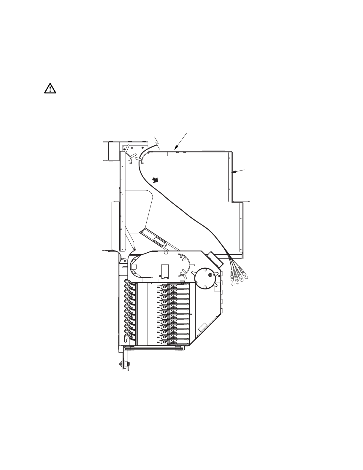
7. Go to the front of the panel and open the hinged drawer. Locate the patch cord connector
in the fiber transport, now located in the rear right of the drawer, as shown in Figure 40.
Caution: Placing a load in excess of 20 pounds onto an open drawer will result in
misalignment or damage to the drawer.
Figure 40. Connector in Fiber Transport When Hinged Drawer is Opened
© 2006, ADC Telecommunications, Inc.
Page 37
Page 45

ADCP-90-297 • Issue 7 • July 2006
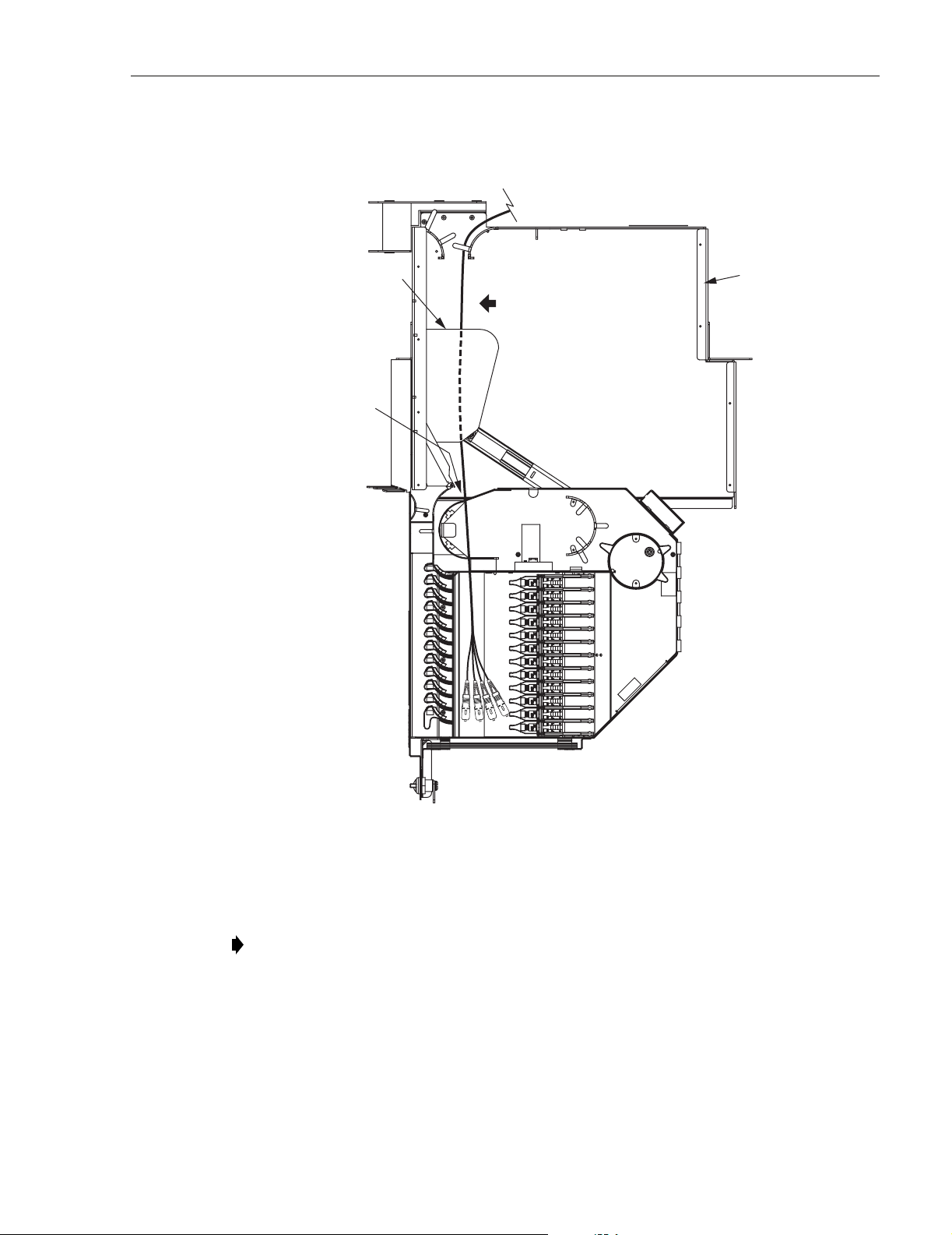
8. Lift up the connector and route the patch cord above and behind the rear top edge of the
hinged drawer and then through the opening on the rear left of the drawer as shown in
Figure 41.
Figure 41. Patch Cord Routed To Left Rear Side of Open Drawer
9. Route the patch cord around radius limiters and spool to the position shown in Figure 42
and Figure 43.
Page 38
© 2006, ADC Telecommunications, Inc.
Figure 42. Patch Cord Routed To Rear Side of Adapter Pack
Page 46

ADCP-90-297 • Issue 7 • July 2006
ROUTE UNDER
PROTECTOR
PLATE
FOT EQUIPMENT
PATCH CORD
PATCH CORD
SLACK LOOP
20292-A
PANEL SHOWN
WITH TOP
REMOVED FOR
CLARITY
CORDS SHOULD BE
LOOSE IN DRAWER.
FIBERS SHOULD NOT
BE TIGHT WHEN SAP
IS RAISED.
Figure 43. Routing FOT Patch Cords Within Standard Termination Panel - Cross-Connect Application
10. Locate and access the adapter pack and adapter (Subsection 5.1) where the patch cord will
be connected.
Danger: Infrared radiation is invisible and can seriously damage the retina of the eye. Do not
look into the ends of any optical fiber. Do not look directly into optical adapters or connectors.
Exposure to invisible laser radiation may result. An optical power meter should be used to
verify active fibers. A protective cap or hood MUST be immediately placed over any radiating
adapter or optical fiber connector to avoid the potential of dangerous amounts of radiation
exposure. This practice also prevents dirt particles from entering the adapter or connector.
11. Remove the dust cap from the adapter and connect the patch cord connector to the adapter.
Note: Always clean and inspect connectors and adapters before mating them. For
guidelines on cleaning connectors, refer to Subsection 5.3.
© 2006, ADC Telecommunications, Inc.
Page 39
Page 47

ADCP-90-297 • Issue 7 • July 2006
12. Adjust the patch cord to provide adequate slack within the drawer. Route extra slack out
through the back of the drawer and secure the patch cords in the cable retention area with
the O-ring provided.
Note: Make sure the patch cords are not pulled tight when the adapter pack is raised.
13. Close the top cover and shut the drawer.
14. Turn the door latch a quarter turn clockwise to secure the door in the closed position.
4.2.2 Interconnect Application
In an interconnect application, FOT patch cords are routed down the front side of the frame and
into the opening on the left side of the standard termination panel. Within the panel, each patch
cord is routed to a specified adapter pack (left side when drawer is open) and connected to the
appropriate adapter. Use the following procedure to install each FOT patch cord in the standard
termination panel:
1. Route the FOT patch cord to the front of the panel as described in Subsection 4.1.
2. Open the panel as described in Subsection 2.3.
Caution: Placing a load in excess of 20 pounds onto an open drawer will result in
misalignment or damage to the drawer.
3. Locate and access the adapter pack and adapter (Subsection 5.1) where the patch cord will
be connected.
Warn ing: Infrared radiation is invisible and can seriously damage the retina of the eye. Do not
look into the ends of any optical fiber. Do not look directly into the optical adapters or
connectors. Exposure to invisible laser radiation may result. An optical power meter should be
used to verify active fibers. A protective cap or hood MUST be immediately placed over any
radiating adapter or optical connector to avoid the potential of dangerous amounts of radiation
exposure. This practice also prevents dirt particles from entering the adapter or connector.
4. Remove the dust cap from the adapter and connect the patch cord connector to the adapter.
5. Route the patch cord within the panel as shown in Figure 44.
Note: Always clean connectors and adapters before mating them. For guidelines on
cleaning connectors, refer to Subsection 5.3.
6. Route the patch cord out and down from the panel as shown in Figure 45.
7. Close the top cover and shut the drawer.
8. Turn the door latch a quarter turn clockwise to secure the door in the closed position.
9. Use the front slack storage spools to take up patch cord slack.
Note: For additional instructions on routing patch cords, refer to the laminated cards
(ADCP-90-296) provided with the frame or the NG3 Fiber Distribution Frame System
User Manual (ADCP-90-298).
Page 40
© 2006, ADC Telecommunications, Inc.
Page 48

PLACE FIBER
UNDER TABS
AND ROUTING
FINGERS
ADCP-90-297 • Issue 7 • July 2006
IFC/OSP
FOT EQUIPMENT
CABLE SUBUNITS
PATCH CORDS
20296-A
Figure 44. Routing FOT Patch Cords Within Standard Termination Panel- Interconnect Applications
FRONT
UPPER
TROUGH
FRONT-TO-REAR
TRANSITION
TROUGH
ALWAYS ROUTE
PATCH CORD
DOWN OUT OF
PANEL
TYPICAL ROUTING OF
PATCH CORD OUT OF PANEL
CAUTION
XXXXXXXXXXXXX
XXXXXXXXXXXXX
XXXXXXXXXXXXX
XXXXXXXXXXXXX
XXXXXXXXXXX
CAUTION
XXXXXXXXXXXXX
XXXXXXXXXXXXX
XXXXXXXXXXXXX
XXXXXXXXXXXXX
XXXXXXXXXXX
CAUTION
XXXXXXXXXXXXX
XXXXXXXXXXXXX
XXXXXXXXXXXXX
XXXXXXXXXXXXX
XXXXXXXXXXX
CAUTION
XXXXXXXXXXXXX
XXXXXXXXXXXXX
XXXXXXXXXXXXX
XXXXXXXXXXXXX
XXXXXXXXXXX
CAUTION
XXXXXXXXXXXXX
XXXXXXXXXXXXX
XXXXXXXXXXXXX
XXXXXXXXXXXXX
XXXXXXXXXXX
CAUTION
XXXXXXXXXXXXX
XXXXXXXXXXXXX
XXXXXXXXXXXXX
XXXXXXXXXXXXX
XXXXXXXXXXX
CAUTION
XXXXXXXXXXXXX
XXXXXXXXXXXXX
XXXXXXXXXXXXX
XXXXXXXXXXXXX
XXXXXXXXXXX
REAR TROUGH
(NOT VISIBLE)
18288-B
Figure 45. Routing FOT Patch Cords Out of Panel - Interconnect Applications
© 2006, ADC Telecommunications, Inc.
Page 41
Page 49

ADCP-90-297 • Issue 7 • July 2006
4.3 Termination/Splice Panel FOT Patch Cord Installation
The termination and splice panel is primarily used in “tie panel” applications and is usually
linked to a standard termination panel with IFC cable. Tie panels are typically used to bridge
any gaps that may exist in between frames. If the termination and splice panel is used in an
application that makes it necessary to route FOT patch cords to the front of the panel, follow the
FOT patch cord routing procedures provided in Subsection 4.2.2.
4.4 VAM Panel FOT Patch Cord Installation
The VAM panel allows optical splitter or wavelength division multiplexing (WDM)
functionality to be incorporated into specified optical circuits at the NG3 frame. FOT patch
cords may be routed into the VAM panel from either the rear side or the front side of the frame.
Whether the FOT patch cords are routed into the VAM panel from the front or rear side is a
matter of convenience and is not related to whether the NG3 frame is used for an interconnect or
cross-connect application. The following subsections provide the procedures for both rear and
front entry FOT patch cord installation:
4.4.1 Rear Entry
For entry from the rear side, FOT patch cords are routed up or down the right rear side of the
frame and into the opening at the rear of the VAM panel. Within the panel, each patch cord is
routed to the specified VAM (left side when drawer is open) and connected to the appropriate
adapter. A label showing the VAM configuration is attached to the side of each VAM. Use the
following procedure when installing FOT patch cords from the rear side of the VAM panel:
1. Route the FOT patch cord to the rear of the panel as described in Subsection 4.1
2. Make sure the hinged drawer on the front of the panel is closed.
3. Locate the fiber transport on the rear side of the panel as shown in Figure 46.
Note: When the hinged drawer is opened, the fiber transport moves to the front right
corner of the panel. The fiber transport holds the patch cord connector as it is pulled to the
front of the panel.
4. Hold the patch cord at the connector and position it in an arc as shown in Figure 47.
Note: The photographs used in this procedure show an early version of the standard
termination panel. However, the basic routing instructions also apply to the current version
of the VAM panel.
Page 42
© 2006, ADC Telecommunications, Inc.
Page 50

FIBER
TRANSPORT
ADCP-90-297 • Issue 7 • July 2006
18314-B
Figure 46. Fiber Transport
Figure 47. Holding Patch Cord
© 2006, ADC Telecommunications, Inc.
Page 43
Page 51

ADCP-90-297 • Issue 7 • July 2006
5. Rotate the looped patch cord over and route it through the radius limiters just below the
fiber transport as shown in Figure 48.
Figure 48. Positioning Patch Cord in Radius limiters
6. Place the patch cord connector in the fiber transport with the connector end facing to the
rear as shown in Figure 49. Be sure the patch cord has about 65 inches (165.10 cm) of
slack so it will not snag when pulled through from the front of the panel.
Figure 49. Connector Oriented Correctly for Placement in Fiber Transport
Page 44
© 2006, ADC Telecommunications, Inc.
Page 52

ADCP-90-297 • Issue 7 • July 2006
7. Go to the front of the panel and open the hinged drawer. Locate the patch cord connector
in the fiber transport now located on the right rear side of the drawer as shown in
Figure 50.
PANEL SHOWN
WITH TOP
REMOVED FOR
CLARITY
FOT EQUIPMENT
PATCH CORD
CONNECTOR IN
FIBER TRANSPORT
20303-A
Figure 50. Connector in Fiber Transport When Hinged Drawer is Opened - Rear Entry
© 2006, ADC Telecommunications, Inc.
Page 45
Page 53

ADCP-90-297 • Issue 7 • July 2006
8. Lift up the connector and route the patch cord above and behind the rear top edge of the
hinged drawer and then through the opening at the rear left corner of the drawer as shown
in Figure 51.
FOT EQUIPMENT
PANEL SHOWN
WITH TOP
REMOVED FOR
CLARITY
PATCH CORD
ROUTE UNDER
PROTECTOR
PLATE
MOVE PATCH CORD
TO LEFT AND LIFT
INTO ENTRY HOLE
20305-A
Figure 51. Positioning Patch Cord Within VAM Panel - Rear Entry
9. Remove the dust caps from the connectors and the VAM adapters and then insert each
connector into the appropriate adapter.
Note: Clean and inspect the connectors and adapters before mating them. For guidelines,
refer to Subsection 5.3.
Page 46
© 2006, ADC Telecommunications, Inc.
Page 54

10. Route the patch cord within the drawer as shown in Figure 52.
PATCH CORD
SLACK LOOP
ADCP-90-297 • Issue 7 • July 2006
PANEL SHOWN
WITH TOP
REMOVED FOR
CLARITY
PLACE FIBER
UNDER ROUTING
FINGER
FOT EQUIPMENT
PATCH CORD
20307-A
Figure 52. Patch Cord Installed In VAM Panel - Rear Entry
Danger: Infrared radiation is invisible and can seriously damage the retina of the eye. Do not
look into the ends of any active optical fiber connector or adapter. Exposure to invisible laser
radiation may result. An optical power meter should be used to verify active fibers. A protective
cap or hood MUST be immediately placed over any radiating adapter or optical fiber connector
to avoid the potential of dangerous amounts of radiation exposure. This practice also prevents
dirt particles from entering the adapter or connector.
11. Store the excess slack by routing the cable fibers around the radius limiter provided (see
Figure 52).
12. Return the VAM to its home position.
13. Continue routing and connecting any remaining connectors on the same cable.
14. When done, close the panel (refer to Subsection 5.5).
© 2006, ADC Telecommunications, Inc.
Page 47
Page 55

ADCP-90-297 • Issue 7 • July 2006
4.4.2 Front Entry
For entry from the front side, FOT patch cords are routed down the left front side of the frame
and into the opening on the left side of the VAM panel. Within the panel, each patch cord is
routed to the specified VAM (left side when drawer is open) and connected to the appropriate
adapter. A label showing the VAM configuration is attached to the side of each VAM. Use the
following procedure when installing FOT patch cords from the front side of the VAM panel:
1. Route the FOT patch cord to the front of the panel as described in Subsection 4.1.
2. Open the panel as described in Subsection 2.3.
Caution: Placing a load in excess of 20 pounds onto an open drawer will result in
misalignment or damage to the drawer.
3. Locate and access the VAM and adapter (Subsection 5.2) where the patch cord will be
connected.
Warn ing: Infrared radiation is invisible and can seriously damage the retina of the eye. Do not
look into the ends of any active optical fiber. Do not look directly into the optical adapters or
connectors. Exposure to invisible laser radiation may result. An optical power meter should be
used to verify active fibers. A protective cap or hood MUST be immediately placed over any
radiating adapter or optical connector to avoid the potential of dangerous amounts of radiation
exposure. This practice also prevents dirt particles from entering the adapter or connector.
4. Remove the dust cap from the adapter and connect the patch cord connector to the adapter.
5. Route the patch cord within the panel as shown in Figure 53.
Note: Always clean connectors and adapters before mating them. For guidelines on
cleaning connectors, refer to Subsection 5.3.
6. Route the patch cord out and down from the panel as shown in Figure 54.
7. Close the top cover and shut the drawer.
8. Turn the door latch a quarter turn clockwise to secure the door in the closed position.
9. Use the front slack storage spools to take up patch cord slack.
Note: For additional instructions on routing patch cords, refer to the laminated cards
(ADCP-90-296) provided with the frame or the NG3 Fiber Distribution Frame System
User Manual (ADCP-90-298).
Page 48
© 2006, ADC Telecommunications, Inc.
Page 56

PLACE FIBER
UNDER TABS
AND ROUTING
FINGERS
ADCP-90-297 • Issue 7 • July 2006
FOT EQUIPMENT
PATCH CORD
20313-A
Figure 53. Routing FOT Patch Cords Within VAM Panel - Front Entry
FRONT
UPPER
TROUGH
FRONT-TO-REAR
TRANSITION
TROUGH
ALWAYS ROUTE
PATCH CORD
DOWN OUT OF
PANEL
TYPICAL ROUTING OF
PATCH CORD OUT OF PANEL
CAUTION
XXXXXXXXXXXXX
XXXXXXXXXXXXX
XXXXXXXXXXXXX
XXXXXXXXXXXXX
XXXXXXXXXXX
CAUTION
XXXXXXXXXXXXX
XXXXXXXXXXXXX
XXXXXXXXXXXXX
XXXXXXXXXXXXX
XXXXXXXXXXX
CAUTION
XXXXXXXXXXXXX
XXXXXXXXXXXXX
XXXXXXXXXXXXX
XXXXXXXXXXXXX
XXXXXXXXXXX
CAUTION
XXXXXXXXXXXXX
XXXXXXXXXXXXX
XXXXXXXXXXXXX
XXXXXXXXXXXXX
XXXXXXXXXXX
CAUTION
XXXXXXXXXXXXX
XXXXXXXXXXXXX
XXXXXXXXXXXXX
XXXXXXXXXXXXX
XXXXXXXXXXX
CAUTION
XXXXXXXXXXXXX
XXXXXXXXXXXXX
XXXXXXXXXXXXX
XXXXXXXXXXXXX
XXXXXXXXXXX
CAUTION
XXXXXXXXXXXXX
XXXXXXXXXXXXX
XXXXXXXXXXXXX
XXXXXXXXXXXXX
XXXXXXXXXXX
REAR TROUGH
(NOT VISIBLE)
18288-B
Figure 54. Routing Patch Cords Out of VAM Panel - Front Entry
© 2006, ADC Telecommunications, Inc.
Page 49
Page 57

ADCP-90-297 • Issue 7 • July 2006
5 OPERATION
Operation of the NG3 termination panel consists of tasks that are typically done after the panel
is installed. Operational tasks include accessing the adapter packs and VAM’s, cleaning
connectors and adapters, installing cross-connect patch cords, and updating designation cards.
Danger: Infrared radiation is invisible and can seriously damage the retina of the eye. Do not
look into the ends of any active optical fiber. Do not look directly into the optical adapters of the
adapter packs. Exposure to invisible laser radiation may result. An optical power meter should
be used to verify active fibers. A protective cap or hood MUST be immediately placed over any
radiating adapter or optical fiber connector to avoid the potential of dangerous amounts of
radiation exposure. This practice also prevents dirt particles from entering the adapter or
connector.
5.1 Adapter Pack Access
Accessing an adapter pack is necessary in order to connect or disconnect a connector and
adapter. Use the following procedure to access an adapter pack:
1. Open the panel as described in Subsection 2.3.
2. Lift up the small tab on top of the adapter pack and lift up the adapter pack to the position
shown in Figure 55.
Page 50
© 2006, ADC Telecommunications, Inc.
18290-B
Figure 55. Adapter Pack In Access Position
Page 58

5.2 VAM Access
Accessing a VAM adapter is necessary in order to connect or disconnect a patch cord from a
VAM. Use the following procedure to access a VAM adapter:
1. Open the panel as described in Subsection 2.3.
2. Lift up the small tab on top of the VAM and lift up the VAM into the position shown in
ADCP-90-297 • Issue 7 • July 2006
Figure 56.
20301-A
VALUE ADDED
MODULE ASSEMBLY
Figure 56. VAM In Access Position
5.3 Cleaning Connectors and Adapters – Standard and Termination/Splice Panels
The connectors and adapters should be carefully cleaned whenever connecting or disconnecting
a fiber optic cable or patch cord. Refer to the Optical Fiber Systems Cleaning and Mating
Instructions (ADCP-90-159) provided with ADC patch cords and optical cable assemblies for
the connector and adapter cleaning procedures. In addition, observe the following guidelines:
© 2006, ADC Telecommunications, Inc.
Page 51
Page 59

ADCP-90-297 • Issue 7 • July 2006
1. A single connector is one-third of an interconnection system comprised of two connectors
and an adapter. If any one of the three components is dirty, it is likely that all three
components are dirty and must be cleaned. Don't mate a “clean” connector with
another connector whose cleanliness is unknown or suspect. If necessary, disconnect
and inspect an installed connector before installing another (clean) connector. Cleaning
the adapter is often also necessary when it is apparent that two pre-cleaned connectors
have become contaminated after installation.
Danger: Infrared radiation is invisible and can seriously damage the retina of the eye. Do not
look into the end of an active optical fiber connector or adapter. Exposure to invisible laser
radiation may result. Use an optical power meter to verify that an optical signal is not present
before looking at a connector endface. Disconnect the signal source if a signal is detected.
2. Inspect the connector endface at 200X. Adjust the microscope to place the fiber in the
upper center of the field of view and rotate the connector to view a 360° area. Focus on
the fiber. Adjust the illuminator and the monitor contrast and brightness so that particles
on the endface and adjacent to the endface are observed. For some inspection systems,
this may involve more than one adjustment at each viewing.
3. If the endface appears to be “very dirty” (liquid-looking droplets, many particles, smears,
etc.), pre-clean the endface with a lint-free laboratory tissue (Kimwipes EX-L or
equivalent) or a Fiberclean cartridge cleaner. When using a cartridge cleaner, use very
light pressure to the non-woven cleaning fabric. Apply 2-3 strokes over the fabric with a
slight rotation of the endface. Keep the endface surface parallel to the cleaning fabric
(this is especially important on angled connectors) and do not reuse any area of the
cartridge fabric. When possible, clean the “sides” (outside diameter) of the ferrule as well
as the endface. If available, use alcohol (reagent or technical grade isopropyl alcohol) with
a lint-free tissue. Moisten (do not saturate) several folds of the tissue with a very small
amount of alcohol and firmly rub/twist the alcohol-moistened portion of the tissue onto the
connector endface, then immediately “final polish” the endface per step 4 or with another
folded dry laboratory tissue.
4. If the endface is just “slightly” dirty (a few very small particles), use a cleaning cartridge
that contains a finely-woven cleaning fabric (such as “reel cleaner” optical connector
cleaner or equivalent) to provide a spot-free, scratch-free, connector endface. Use a very
light pressure to the cleaning fabric. Apply 2-3 strokes over the fabric with a slight rotation
of the endface. Keep the endface surface parallel to the cleaning media (this is especially
important on angled connectors) and do not reuse any area of the cartridge fabric. Folding
a lint-free tissue into 4 to 6 layers and lightly applying it to the endface will also
accomplish this purpose.
5. Reject any connectors that do not clean up, are scratched (no defects permitted in the fiber
core), or have many or large pits in the endface ceramic adjacent to the fiber (within
approximately 100 microns or roughly a fiber diameter).
6. Avoid the use of compressed air or “canned gas” to clean non-angled endfaces. If canned
gas is used to clean any components, exercise extreme care not to tip/tilt the container
during its use as liquid material will be ejected and deposited onto the endface. Low
quality compressed air or improper use of canned gas can cause more endface
contamination than it removes.
7. Re-inspect each endface after cleaning.
Page 52
© 2006, ADC Telecommunications, Inc.
Page 60

5.4 Cross-Connect Jumper Patch Cord Routing
5.4.1 Standard Termination Panel and Termination/Splice Panel Cross-Connect Routing
Cross-connect patch cords are used in a cross-connect application to provide a link between
adapters located in different panels. Usually, one of these panels is dedicated to OSP cable
terminations and the other panel is dedicated to FOT equipment terminations. Use the following
procedure install a cross-connect patch cord:
1. Open the panel as described in Subsection 2.3.
2. Locate and access the adapter pack of interest as described in Subsection 5.1.
Danger: Infrared radiation is invisible and can seriously damage the retina of the eye. Do not
look into the ends of any optical fiber. Do not look directly into the optical adapters of the
adapter packs. Exposure to invisible laser radiation may result. A protective cap or hood MUST
be immediately placed over any radiating adapter or optical fiber connector to avoid the
potential of dangerous amounts of radiation exposure. This practice also prevents dirt particles
from entering the adapter or connector.
ADCP-90-297 • Issue 7 • July 2006
PLACE FIBER
UNDER TABS
AND ROUTING
FINGERS
CROSS-CONNECT
PATCH CORDS
Figure 57. Connecting a Cross-Connect Patch Cord
FOT OR OSP
FIBERS
20314-A
Page 53
© 2006, ADC Telecommunications, Inc.
Page 61

ADCP-90-297 • Issue 7 • July 2006
3. Remove the dust cap from the adapter and connect the patch cord connector to the front
side of the adapter pack (left side when drawer is open), as shown in Figure 57.
Note: Always clean connectors and adapters before mating them. For guidelines on
cleaning connectors, refer to Subsection 5.3.
4. Route the patch cord within the drawer through the radius limiters as also shown in
Figure 57.
5. Route the patch cord out of the drawer and down along the front of the frame, as shown in
Figure 58.
Note: Never route up out the panel. Always route down.
6. For routing guidelines beyond this point, refer to the laminated card hanging on the frame
(ADCP-90-296) or to the frame user manual (ADCP-90-298).
FRONT
UPPER
TROUGH
TYPICAL ROUTING OF
PATCH CORD OUT OF PANEL
5.4.2 VAM Panel Cross-Connect Patch Cord Routing
The VAM panel may be used in applications where it is necessary to route cross-connect patch
cords to the front of the panel. If this is the case, follow the FOT equipment patch cord routing
procedures provided in Subsection 4.4.2 when routing cross-connect patch cords to the front
side of the VAM panel.
5.5 Closing the Panel
FRONT-TO-REAR
TRANSITION
TROUGH
ALWAYS ROUTE
PATCH CORD
DOWN OUT OF
PANEL
CAUTION
XXXXXXXXXXXXX
XXXXXXXXXXXXX
XXXXXXXXXXXXX
XXXXXXXXXXXXX
XXXXXXXXXXX
CAUTION
XXXXXXXXXXXXX
XXXXXXXXXXXXX
XXXXXXXXXXXXX
XXXXXXXXXXXXX
XXXXXXXXXXX
CAUTION
XXXXXXXXXXXXX
XXXXXXXXXXXXX
XXXXXXXXXXXXX
XXXXXXXXXXXXX
XXXXXXXXXXX
CAUTION
XXXXXXXXXXXXX
XXXXXXXXXXXXX
XXXXXXXXXXXXX
XXXXXXXXXXXXX
XXXXXXXXXXX
CAUTION
XXXXXXXXXXXXX
XXXXXXXXXXXXX
XXXXXXXXXXXXX
XXXXXXXXXXXXX
XXXXXXXXXXX
CAUTION
XXXXXXXXXXXXX
XXXXXXXXXXXXX
XXXXXXXXXXXXX
XXXXXXXXXXXXX
XXXXXXXXXXX
CAUTION
XXXXXXXXXXXXX
XXXXXXXXXXXXX
XXXXXXXXXXXXX
XXXXXXXXXXXXX
XXXXXXXXXXX
Figure 58. Patch Cord Routing From Panel
REAR TROUGH
(NOT VISIBLE)
18288-B
Use the following procedure to close the panel:
1. Check to ensure that all unterminated adapters are capped with dust covers. Return all
adapter packs or VAMs to their home positions (seated fully down).
2. Close the top cover of the drawer.
3. Close the hinged drawer.
4. Turn the door latch a quarter turn clockwise to secure the door in the closed position.
Page 54
© 2006, ADC Telecommunications, Inc.
Page 62

6 MAINTENANCE
6.1 Cable Replacement – Standard Panel
Use the following procedure to remove and replace an installed IFC cable from a standard
termination panel. Refer to Figure 59 as needed during the procedure.
Danger: Infrared radiation is invisible and can seriously damage the retina of the eye. Do not
look into the ends of any optical fiber. Do not look directly into the optical adapters of the
adapter packs. Exposure to invisible laser radiation may result. An optical power meter should
be used to verify active fibers. A protective cap or hood MUST be immediately placed over any
radiating adapter or optical fiber connector to avoid the potential of dangerous amounts of
radiation exposure. This practice also prevents dirt particles from entering the adapter or
connector.
ADCP-90-297 • Issue 7 • July 2006
REMOVE
CABLE
SUBUNITS
FROM
CABLE
FINGERS
DETAIL A
SEE DETAIL A IF
THE IFC CABLE WAS
FACTORY INSTALLED
LIFT CABLE
FIBERS FROM
RADIUS LIMITERS
SLIDE BUNDLED
FIBERS OUT
FROM REAR
6
LIFT CABLE
FIBERS OUT
OF CABLE
ENTRY HOLE
4
RADIUS
LIMITER
3
RADIUS
LIMITER
MOVE BUNDLED
FIBERS TO THE RIGHT
5
SLACK
SPOOL
SLACK SPOOL
20318-A
PANEL SHOWN
WITH TOP
REMOVED FOR
CLARITY
LIFT CABLE
FIBERS FROM
2
REMOVE
CONNECTORS
FROM ADAPTERS
1
Figure 59. Removing an IFC Cable From a Standard Termination Panel
© 2006, ADC Telecommunications, Inc.
Page 55
Page 63

ADCP-90-297 • Issue 7 • July 2006
1. Verify that the cable being removed has no active circuits. If it does, inactivate the circuits
before proceeding.
2. Open the panel as described in Subsection 2.3.
3. Locate and access the adapter packs (see Subsection 5.1) one at a time, removing all the
cable connectors from the adapters. As each connector is disconnected, immediately cover
the exposed adapter with a dust cover.
4. Unlatch the O-ring in the cable retention area.
5. Bundle together the connectors and lift the cable fibers from the slack spool and radius
limiters within the hinged drawer.
6. Lift the cable fibers out of the cable entry hole (left rear side of the drawer) and move the
bundled fibers to the right along the top rear edge of the drawer to the opening on the right
between the drawer and the panel chassis.
7. Place the cable bundle just inside the panel chassis and close top cover of hinged drawer.
8. Go to the rear of the panel and slide the bundled connectors out of the panel through the
opening on the right rear side.
Note: If the IFC cable was factory installed, you will need to release the cable fibers from
the cable fingers on the interior right side of the chassis.
9. Disassemble the cable clamp to release the cable from the clamp. Set aside the cable
clamp components for use with the replacement cable, if any.
10. Trace the cable back along the frame, removing any wax lacing securing the cable to cable
tie bars. If other cables are secured by the same lacing and no other cable is being installed
at this time, secure the remaining using wax lacing.
11. Remove the cable completely from the frame and any external support. Set the cable aside
for removal from the building.
12. Install a new cable following the cable installation procedure (see Section 3).
6.2 Removing a Patch Cord – All Panel Types
Use the following procedure to remove a patch cord:
1. Open the panel as described in Subsection 2.3.
2. Locate and access the adapter pack as described in Subsection 5.1.
3. Carefully disconnect the patch cord connector from the adapter and immediately cover the
adapter with a dust cover.
4. Carefully trace back the patch cord along its route, extricating it from other patch cords.
Be careful not to bend or damage other patch cords.
Page 56
© 2006, ADC Telecommunications, Inc.
Page 64

6.3 Replacing an Adapter – Standard Panel and Termination/Splice Panel
If an individual adapter becomes damaged or contaminated, it can be replaced. Any connectors
connected to the adapter must first be removed. The adapter can then be released from the
adapter pack. Use the following procedure to replace an adapter:
1. Open the panel as described in Subsection 2.3.
Caution: Placing a load in excess of 20 pounds onto an open drawer will result in
misalignment or damage to the drawer.
2. Verify that the optical fibers that you are about to disconnect are not carrying an active
signal. Inactivate the signal before proceeding.
Danger: Infrared radiation is invisible and can seriously damage the retina of the eye. Do not
look into the ends of any optical fiber. Do not look directly into the optical adapters of the
adapter packs. Exposure to invisible laser radiation may result. An optical power meter should
be used to verify active fibers. A protective cap or hood MUST be immediately placed over any
radiating adapter or optical fiber connector to avoid the potential of dangerous amounts of
radiation exposure. This practice also prevents dirt particles from entering the adapter or
connector.
ADCP-90-297 • Issue 7 • July 2006
3. Locate and access the adapter pack as described in Subsection 5.1 and as shown in
Figure 60.
Note: The photographs used in this procedure show an early version of the standard
termination panel. However, the adapter replacement instructions also apply to current
versions of the standard termination panel and the termination/splice panel.
Figure 60. Accessing Adapter Pack
© 2006, ADC Telecommunications, Inc.
Page 57
Page 65

ADCP-90-297 • Issue 7 • July 2006
4. Remove the front side connector from the adapter pack and immediately cover it with a
dust cap as shown in Figure 61. Set aside the front side connector.
Figure 61. Removing Front Side Connector
5. Remove the rear side connector and immediately cover it with a dust cap as shown in
Figure 62. Set aside the rear side connector.
Page 58
© 2006, ADC Telecommunications, Inc.
Figure 62. Removing Rear Side Connector
Page 66

ADCP-90-297 • Issue 7 • July 2006
6. Using a small flat screwdriver, press against the adapter spring clip in the location shown
in Figure 63. While pressing in the spring clip, push the adapter gently with your finger to
prevent the spring clip from snapping back into position.
Figure 63. Pressing in Spring Clip on Adapter
7. Using the small flat screw driver, press in the spring clip on the other side of the adapter as
shown in Figure 64. This will free the adapter from the adapter pack.
Figure 64. Pressing in Spring Clip on Other Side of Adapter
© 2006, ADC Telecommunications, Inc.
Page 59
Page 67

ADCP-90-297 • Issue 7 • July 2006
8. Remove the adapter fully from the adapter pack by gently sliding the adapter forward as
shown in Figure 65.
Figure 65. Removed Adapter
9. Position the new adapter for installation as shown in Figure 66.
Page 60
© 2006, ADC Telecommunications, Inc.
Figure 66. Positioning New Adapter for Installation
Page 68

ADCP-90-297 • Issue 7 • July 2006
10. Slide the new adapter into the adapter pack until it clicks into place as shown in Figure 67.
Figure 67. Installed New Adapter
11. Remove dust caps from new adapter and from the connectors previously set aside.
Note: Always clean and inspect connectors and adapters before mating them. For
guidelines on cleaning connectors, refer to Subsection 5.3.
12. Re-connect the connectors as shown in Figure 68 and then slide down the adapter pack
into the closed position. Close the panel when finished.
Figure 68. Reinstalled Connectors
© 2006, ADC Telecommunications, Inc.
Page 61
Page 69

ADCP-90-297 • Issue 7 • July 2006
6.4 Replacing an Adapter Pack – Standard Panel and Termination/Splice Panel
All NG3 termination panels ship with the adapters loaded. Use the following procedure if it is
necessary to remove and replace an adapter pack.
1. Open the panel as described in Subsection 2.3.
Caution: Placing a load in excess of 20 pounds onto an open drawer will result in
misalignment or damage to the drawer.
2. Locate and access the adapter pack as described in Subsection 5.1 and as shown in
Figure 69.
Note: The photographs used in this procedure show an early version of the standard
termination panel. However, the adapter replacement instructions also apply to current
versions of the standard termination panel and the termination/splice panel.
Page 62
Figure 69. Accessing Adapter Pack
3. Verify that any optical fibers that may need to be disconnected are not carrying an active
optical signal. Inactivate the signal before proceeding
Warn ing: Infrared radiation is invisible and can seriously damage the retina of the eye. Do not
look into the ends of any optical fiber. Do not look directly into the optical adapters or
connectors. Exposure to invisible laser radiation may result. An optical power meter should be
used to verify active fibers. A protective cap or hood MUST be immediately placed over any
radiating adapter or optical connector to avoid the potential of dangerous amounts of radiation
exposure. This practice also prevents dirt particles from entering the adapter or connector.
4. Remove each front side connector from the adapter pack adapter and immediately cover
with a dust cap as shown in Figure 70. Label and then set aside.
Page 70

ADCP-90-297 • Issue 7 • July 2006
Figure 70. Removing Front Side Connectors
5. Remove each rear side connector from the adapter pack adapter and immediately cover
with a dust cap as shown in Figure 71. Label and then set aside.
Figure 71. Removing Rear Side Connectors
6. From the front, pull outward on the tab located underneath the adapter pack assembly
while at the same time pulling upward on the adapter pack as shown in Figure 72.
© 2006, ADC Telecommunications, Inc.
Page 63
Page 71

ADCP-90-297 • Issue 7 • July 2006
7. When the adapter pack releases, pull it free of the mounting slot.
8. Align the replacement adapter pack with the opening in the mounting slot and slide it
down until it clicks into the access position.
PULL UPWARD
ON ADAPTER
PAC K
PULL OUTWARD
ON TAB
20316-A
Figure 72. Removing Adapter Pack
9. Remove the dust caps from the adapters on the replacement adapter pack and from the
connectors previously set aside.
Note: Always clean and inspect connectors and adapters before mating them. For
guidelines on cleaning connectors, refer to Subsection 5.3.
10. Re-connect the connectors as shown in Figure 73 and then slide down the adapter pack
into the closed position. Close the panel when finished.
Page 64
© 2006, ADC Telecommunications, Inc.
Figure 73. Reinstalled Connectors
Page 72

6.5 Replacing a VAM
Use the following procedure if it is necessary to remove and replace a VAM:
1. Open the panel as described in Subsection 2.3.
Caution: Placing a load in excess of 20 pounds onto an open drawer will result in
misalignment or damage to the drawer.
2. Lift up the small tab on top of the VAM and lift up the VAM into the position shown in
Figure 69.
ADCP-90-297 • Issue 7 • July 2006
20301-A
VALUE ADDED
MODULE ASSEMBLY
Figure 74. Accessing VAM
3. Verify that any optical fibers that may need to be disconnected are not carrying an active
optical signal. Inactivate the signal before proceeding.
Warn ing: Infrared radiation is invisible and can seriously damage the retina of the eye. Do not
look into the ends of any optical fiber. Do not look directly into the optical adapters or
connectors. Exposure to invisible laser radiation may result. An optical power meter should be
used to verify active fibers. A protective cap or hood MUST be immediately placed over any
radiating adapter or optical connector to avoid the potential of dangerous amounts of radiation
exposure. This practice also prevents dirt particles from entering the adapter or connector.
© 2006, ADC Telecommunications, Inc.
Page 65
Page 73

ADCP-90-297 • Issue 7 • July 2006
4. Remove each patch cord connector from the VAM adapter and then immediately cover the
exposed connector with a dust cap. Label and then set aside.
5. From the front, pull outward on the tab located underneath the VAM assembly while at the
same time pulling upward on the VAM as shown in Figure 75.
PULL UPWARD
ON VAM
20317-A
PULL OUTWARD
ON TAB
Figure 75. Removing VAM
6. When the VAM releases, pull it free of the mounting slot.
7. Align the replacement VAM with the opening in the mounting slot and slide it down until
it clicks into the access position.
8. Remove the dust caps from the adapters on the replacement VAM and from the patch cord
connectors previously set aside.
Note: Always clean and inspect connectors and adapters before mating them. For
guidelines on cleaning connectors, refer to Subsection 5.3.
9. Re-connect the patch cord connectors to the VAM adapters and then slide down the VAM
into the closed position. Close the panel when finished.
Page 66
© 2006, ADC Telecommunications, Inc.
Page 74

7 CUSTOMER INFORMATION AND ASSISTANCE
PHONE:
EUROPE
Sales Administration: +32-2-712-65 00
Technical Assistance: +32-2-712-65 42
EUROPEAN TOLL FREE NUMBERS
Germany:
UK:
Spain:
France:
Italy: 0800 782374
U.S.A. OR CANADA
Sales: 1-800-366-3891 Extension 73000
Technical Assistance: 1-800-366-3891
Connectivity Extension 73475
Wireless Extension 73476
ASIA/PACIFIC
Sales Administration: +65-6294-9948
Technical Assistance: +65-6393-0739
ELSEWHERE
Sales Administration: +1-952-938-8080
Technical Assistance: +1-952-917-3475
WRITE:
ADC TELECOMMUNICATIONS, INC
PO BOX 1101,
MINNEAPOLIS, MN 55440-1101, USA
0180 2232923
0800 960236
900 983291
0800 914032
ADCP-90-297 • Issue 7 • July 2006
ADC TELECOMMUNICATIONS (S'PORE) PTE. LTD.
100 BEACH ROAD, #18-01, SHAW TOWERS.
SINGAPORE 189702.
ADC EUROPEAN CUSTOMER SERVICE, INC
BELGICASTRAAT 2,
1930 ZAVENTEM, BELGIUM
PRODUCT INFORMATION AND TECHNICAL ASSISTANCE:
connectivity.tac@adc.com
wireless.tac@adc.com
euro.tac@adc.com
asiapacific.tac@adc.com
Contents herein are current as of the date of publication. ADC reserves the right to change the contents without prior notice.
In no event shall ADC be liable for any damages resulting from loss of data, loss of use, or loss of profits and ADC further
disclaims any and all liability for indirect, incidental, special, consequential or other similar damages. This disclaimer of
liability applies to all products, publications and services during and after the warranty period. This publication may be
verified at any time by contacting ADC's Technical Assistance Center.
© 2006, ADC Telecommunications, Inc.
13944-M
All Rights Reserved
Printed in U.S.A.
© 2006, ADC Telecommunications, Inc.
Page 67
Page 75

Page 76

www.adc.com
i
 Loading...