

Page 1
FlexDSX
®
Super High Density Bay
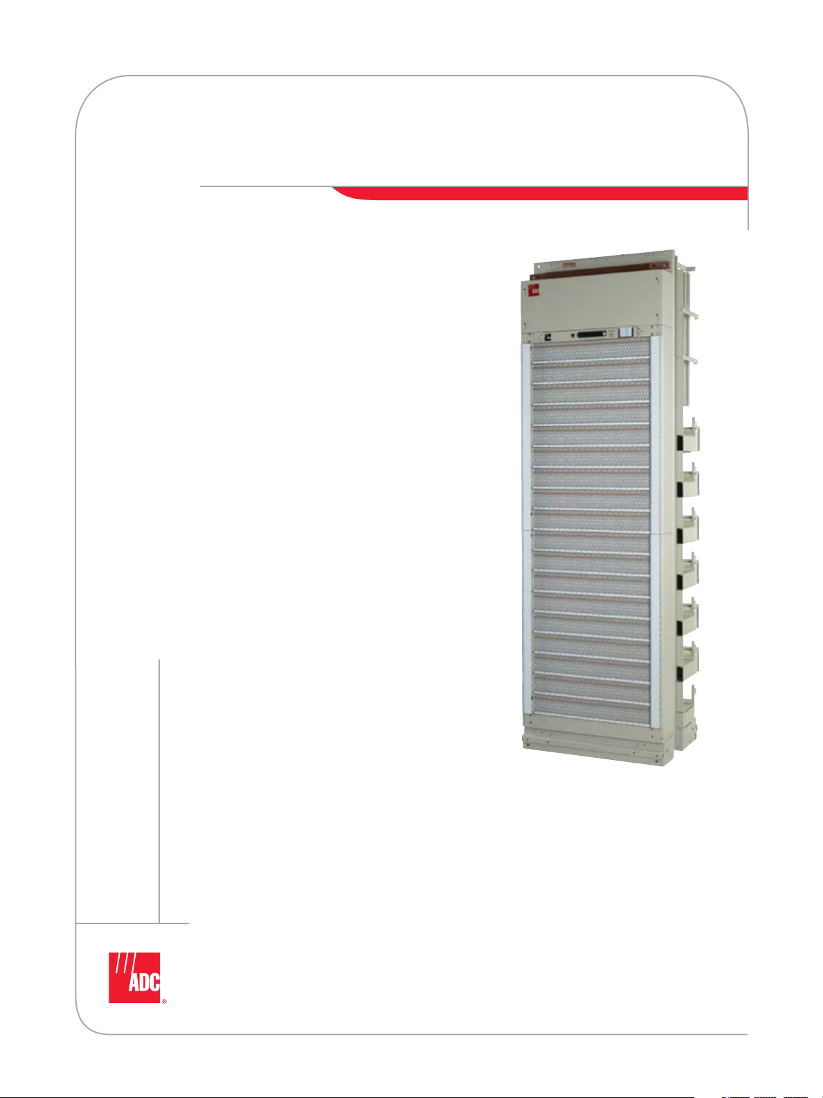
ADC’s FlexDSX® Super High Density Bay
is engineered to help service providers
manage network connectivity and operations.
Using new techniques built upon ADC’s 40
years of proven experience, the FlexDSX
Super High Density Bay is the only bay to
offer highest density with trouble-free cable
management and enhanced functionality.
Quick to install, easy to manage and
maintain, the FlexDSX Super High Density
Bay maximizes network termination density,
simplifies engineering and is designed to
match service provider applications.
Service providers are challenged everyday with
maintaining customer service while planning
growth strategies, increasing operational
efficiency, and reducing costs. Building a
flexible network is critical to maintaining
day-to-day operations while creating an
infrastructure that will position service
providers for future growth and expansion.
FlexDSX Super High Density Bay features:
• Easy to install
• Easy to manage and maintain
• Maximizes the termination density
of the network
• Simplifies engineering
• Matches service provider applications
• Trouble-free cable management
• ADC reliable DSX Jack Technology
Spec Sheet
*ADC DSX jack maintains lifetime warranty
w w w . a d c . c o m • + 1 - 9 5 2 - 9 3 8 - 8 0 8 0 • 1 - 8 0 0 - 3 6 6 - 3 8 9 1
Page 2
FlexDSX
®
Super High Density Bay
Introduction
ADC’s FlexDSX® Super High Density Bay offers greater termination density as well as built-in,
trouble-free cable management for flexible network planning, installation and maintenance.
ADC’s FlexDSX Super High Density Bay design is unmatched in the marketplace. ADC’s vertical IN/OUT
terminal blocks with extra cabling space and cable management fanning strips provide 50 percent more
cabling space than traditional high-density bays. Simultaneously, it provides increased jumper capacity
to simplify cross-connect wire management for easy operation and maintenance. The FlexDSX Super
High Density design incorporates a recessed vertical wireway for cross-connect cabling and up to seven
horizontal cross-connect jumper wireways instead of the standard two wireways. Vertical and horizontal
wireways are on separate planes to avoid congestion and pile up at intersections.
The FlexDSX Super High Density Bay enables service providers to realize additional cost savings by
conserving valuable floor space. The bay provides more than 30% floor space savings, while doubling
the density and provides dual monitoring with ADC’s reliable FlexDSX Jack Technology.
Description
The FlexDSX Super High Density Bay achieves greater density in a 7' height x 26" width x 18" depth,
accommodating up to 1512 (7') usable DSX jack terminations. ADC’s flexible ordering guide allows
bay designs in 64 or 84 jacks per panel. This eliminates jack waste or complications in circuit
management administration.
®
6 / 0 7 • 1 0 4 8 9 7 A E
Super High Density Bay
FlexDSX
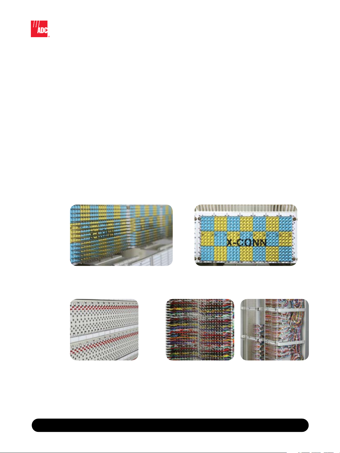
• Provides clear identification of each circuit by offering expanded labeling space
improving network documentation and decreasing potential mistakes while troubleshooting
• Colored cross-connect labels allow for easy determination of circuit terminations
• Flashing LED and dual monitoring
• Block's design provides better cable management and more
space for cables
• Cable entry is allowed on both sides of block
w w w . a d c . c o m • + 1 - 9 5 2 - 9 3 8 - 8 0 8 0 • 1 - 8 0 0 - 3 6 6 - 3 8 9 1
2
Page 3

FlexDSX
®
Super High Density Bay
• 1512 jacks per 7' bay uses an efficient jack count of 84 jacks
per panel. Dual monitoring of the out and in ports, panel
termination count matches digital switching Broadband
equipment for simplified network engineering. Consists of 18
panels of 84 jacks in a single plane.
• More than 30% floor space savings – the industry’s highest
DSX density improves profitability by conserving valuable floor
space. Service providers can realize more revenue and more
space for other revenue generating network equipment.
• Incorporating vertical IN/OUT terminal blocks with extra
cabling space and cable management strips provide 50%
more cabling space than traditional high-density bays.
Increased lineup density saves valuable floor space and reduces
costs by eliminating the need for bay spacers. Dual hinged
doors with designation labels on both sides provide double
the designation space. Adhesive backed labels guarantee
the identification designations will always be available. The
expanded label space minimizes the possibility of mistakes
during trouble shooting as all circuits are clearly identified.
• Built-in trouble free cross-connect cable management provides
increased jumper capacity. ADC’s cable management system
eases operations and maintenance by reducing cross-connect
jumper congestion and pileup.
®
6 / 0 7 • 1 0 4 8 9 7 A E
Super High Density Bay
FlexDSX
• Each standard bay comes with 160 tie pair terminations (two
80 termination wire wrap blocks). Built-in cross aisle tie blocks
ensure the ability to grow new lineups without sacrificing
overall termination density.
• The rear cross-connect high density design allows for all jack
maintenance activities to remain at an arm’s length.
• Guarantees a worry-free maintenance environment with over
40 years of proven jack quality and reliability and a lifetime
warranty. All components of the bay are made by ADC,
Super High Density Bay
O r d e r i n g I n f o r m a t i o n
Description
Concentration bays, 2.14 m (7')
Overhead cabling 84 1512 160 DFX-SHD001
Raised floor cabling 84 1512 160 DFX-SHD002
Maintenance bays, 2.14 m (7')
Overhead cabling 84 1344 160 DFX-SHD003*
Raised floor cabling 84 1344 160 DFX-SHD004*
Overhead cabling denotes the cable enters the top of the bay and the equipment termination blocks are at the top
of the bay. Raised floor cabling denotes the cable enters from the raised floor into the bottom of the bay and the
equipment blocks are at the bottom of the bay.
*Maintenance bays are equipped with one 56-position interbay panel.
ensuring quality from beginning to end.
Jacks Per
Panel
# of
Terminations
# of Tie Pair
Circuits
Catalog
Number
w w w . a d c . c o m • + 1 - 9 5 2 - 9 3 8 - 8 0 8 0 • 1 - 8 0 0 - 3 6 6 - 3 8 9 1
3
Page 4

Accessories
O r d e r i n g I n f o r m a t i o n
Description Catalog Number
AC outlet kit; accepts outlet kits in front only, North American ACOK-PWNB
End guards; 2.14 m (7') height x 298 mm (18.75") width SHD-HR-85
Installation kits
Concrete floor, overhead cabling RINST-FLR
Raised floor SHD-HR-91
Raised floor (zone 4 rated);
for use without overhead cable racking
2.14 m (7') network rack kit includes:
(1) raised floor mounting kit
(12) rack tie bracket kits
(1) rack grounding kit
Rack extender; 2.14 m (7') to 3.5 m (11.5') SHD-HR-44N
RINST-DSXRFL-PW
Spec Sheet
Website: www.adc.com
From North America, Call Toll Free: 1-800-366-3891 • Outside of North America: +1-952-938-8080
Fax: +1-952-917-3237 • For a listing of ADC’s global sales office locations, please refer to our website.
ADC Telecommunications, Inc., P.O. Box 1101, Minneapolis, Minnesota USA 55440-1101
Specifications published here are current as of the date of publication of this document. Because we are continuously
improving our products, ADC reserves the right to change specifications without prior notice. At any time, you may
verify product specifications by contacting our headquarters office in Minneapolis. ADC Telecommunications, Inc.
views its patent portfolio as an important corporate asset and vigorously enforces its patents. Products or features
contained herein may be covered by one or more U.S. or foreign patents. An Equal Opportunity Employer
104897AE 6/07 Revision © 2007, 2003 ADC Telecommunications, Inc. All Rights Reserved
 Loading...