

Page 1

InterReach Fusion Wideband
Installation, Operation, and Reference Manual
TECP-77-044 · Issue 9 · March 2015
D-620616-0-20 Rev K
Page 2

Copyright
© 2015 TE Connectivity, Inc. All Rights Reserved.
Information contained in this document
is company private to TE Connectivity Ltd., and shall not be modified,
used, copied, reproduced or disclosed in whole or in part without the written consent of TE.
Trademark Information
TE Connectivity, TE and TE connectivity (logo) FlexWave, InterReach, InterReach Fusion and InterReach Unison
are trademarks.
All other logos, products and/or c
ompany names referred to herein might be trademarks of their respective
owners.
Disclaimer of Liability
The information given herein, including drawings, illustrations and schematics which are intended for illustration
purposes only, is believed to be reliable. However, TE Connectivity makes no warranties as to its accuracy or
completeness and disclaims any liability in connection with its use. TE Connectivity's obligations shall only be as
set forth in TE Connectivity's Standard Terms and Conditions of Sale for this product and in no case will TE
Connectivity be liable for any incidental, indirect or consequential damages arising out of the sale, resale, use or
misuse of the product. Users of TE Connectivity products should make their own evaluation to determine the
suitability of each such product for the specific application.
REVISION HISTORY
ISSUE DATE REASON FOR CHANGE
1 7/2008 First release
2 10/2008 Add Fusion Wideband 1900/AWS product content
0 MI
3 8/2009 Add Fusion Wideband 700/AWS and 70
4 5/2010 Add Fusion Wideband 700 (Lower
5 9/2011 Add Fusion Wideband 2600 MIMO product content
6 11/2012 Add Fusion Wideband 700 ABC/AWS HP/AWS HP an
7 11/2013 Add Fusion Wideband 2100 HP/1800 HP and Fusio n
8 7/2014 Add Fusion Wideband 2100 HP/2600 HP product content
9 3/2015 Add Fusion Wideband 2500/2500 product content.
product content
ABC) MIMO product content
MO product content
d Fusio
n Wideband 700 UC/AWS HP/AWS HP
Wideband 850/1900 HP/AWP HP product content
Page 3

TABLE OF CONTENTS
Preface ______________________________________________________________________ 1
Purpose and Scope .................................................................................................................................................................. 2
Conventions Used in this Manual............................................................................................................................................. 3
Measurements ........................................................................................................................
Document Cautions and Notes...................................................................................................................................................3
Document Fonts ......................................................................................................................
Related Publications ................................................................................................................................................................4
InterReach Fusion Wideband System Description ____________________________________ 5
System Overview ..................................................................................................................................................................... 5
Wireless Standards and Air Interface Protocols.........................................................................................................................6
Configurable Bands.....................................................................................................................................................................6
Key System Features....................................................................................................................
System Hardware .................................................................................................................................................................... 8
System OA&M Capabilities .................................................................................................................................................... 10
System Monitoring and Reporting ......................
Using Alarm Contacts ...............................................................................................................................................................12
System Connectivity .............................................................................................................................................................. 13
System Operation ..................................................................................................................................................................
System Specifications ............................................................................................................................................................ 15
RF End-to-End Performance ................................................................................................................................................... 18
2100/1800 RAU (FSN-W1-2118-1)..........................................................................................................
2100 HP/1800 HP (FSN-W1-2118-1-HP)...................................................................................................................................19
2100 HP/2600 HP (FSN-W1-2126-1-HP)...................................................................................................................................20
2100 High Power RAU (FSN-W1-21HP-1) ........................
1900/AWS RAU (FSN-W1-1921-1)............................................................................................................................................21
800/850/1900 RAU (FSN-W2-808519-1)..................................................................................................................................22
700/AWS RAU (FSN-W2-7021-1)............................................................................................................
700/700 (Upper C) MIMO RAU (FSN-W2-7575-1)....................................................................................................................24
700/700 (Lower ABC) MIMO RAU (FSN-W2-7070-1)................................................................................................................24
700 ABC/AWS HP/AWS HP RAU (FSN-W4-702121-1-HP).......................................................................................
700 UC/AWS HP/AWS HP RAU (FSN-W4-752121-1-HP)...........................................................................................................26
850/1900 HP/AWS HP RAU (FSN-W5-851921-1-HP)................................................................................................................27
2500/2500 RAU (FSN-2525-1-TDD) ........................................................................................................
2600/2600 RAU (FSN-W3-2626-1)..........................................................................................................
.....................................................................................................................11
.........................................................................................................20
...................................................3
...................................................3
...............................................6
14
..................................18
..................................23
..................25
..................................28
..................................28
Fusion Wideband Main Hub ____________________________________________________ 29
Fusion Wideband Main Hub Overview................................................................................................................................... 30
Fusion Wideband Main Hub Front Panel
Uplink/Downlink Optical-Fiber Ports........................................................................................................................................33
Main Hub LED Indicators .............................................................................................................
Unit STATUS LEDs ...................................................................................................................
Fiber Port LEDs .......................................................................................................................
Communications RS-232 Serial Connector
Fusion Wideband Main Hub Rear Panel.................................................................................................
Main Hub Specifications ........................................................................................................................................................ 37
Faults, Warnings, and Status Mess
nts ..............................................................................................................................
Eve
View Alarm Preferences ..............................................................................................................
InterReach Fusion Wideband Installation, Operation, and Reference Manual Page iii
TECP-77-044 • Issue 9 • March 2015 ©2015 TE Connectivity Ltd.
................................................................................................................................ 32
.............................................33
..........................................34
..........................................35
...............................................................................................................................35
..................................36
ages.................................................................................................................................. 38
.........................................................38
.............................................39
Page 4

Table of Contents
Fusion Wideband Expansion Hub ________________________________________________ 41
Expansion Hub Overview ....................................................................................................................................................... 42
Expansion Hub Front Panel ......................................................................................................................................................44
Optical Fiber Uplink/Downlink Connectors.............................................................................................
LED Indicators...........................................................................................................................................................................45
Unit Status and DL/UL STATUS LEDs.................................................................................................................................45
Port STATUS LEDs ....................................................................................................................
Expansion Hub Rear Panel ..................................................................................................................................................... 48
Faults, Warnings, and Status Messages.................................................................................................................................. 49
ion Hub Specifications................................................................................................................................................. 50
Expans
.................................45
.........................................47
Remote Access Unit ___________________________________________________________ 51
Overview ............................................................................................................................................................................... 52
RAU Front Panel .......................................................................................................................................................................55
RAU Back Panel ........................................................................................................................................................................56
RAU LED Indicators ................................................................................................................................................................ 57
TUS LEDs.............................................................................................................................................................................57
STA
Faults and Warnings .............................................................................................................................................................. 58
Remote Access Unit Specificatio
ns......................................................................................................................................... 59
Designing a Fusion Wideband Solution ___________________________________________ 61
Design Overview.................................................................................................................................................................... 62
Downlink RSSI Design Goal ....................................................................................................................................................
Maximum Output Power Per Carrier...................................................................................................................................... 65
700/AWS RAU (FSN-W2-7021-1)..............................................................................................................................................66
700 MHz (Upper C) MIMO RAU (FSN-W2-7575-1) .........................................................................................
700 MHz (Lower ABC) MIMO RAU (FSN-W2-7070-1)...............................................................................................................67
700 ABC/AWS HP/AWS HP RAU (FSN-W4-702121-1-HP).........................................................................................................68
700 UC/AWS HP/AWS HP RAU (FSN-W4-752121-1-HP) ........................................................................................
800/850/1900 RAU (FSN-W2-808519-1)..................................................................................................................................70
850/1900 HP/AWS HP RAU (FSN-W5-851921-1-HP)................................................................................................................73
1900/AWS RAU (FSN-W1-1921-1)...........................................................................................................
2100/1800 RAU (FSN-W1-2118-1) ...........................................................................................................................................77
2100 HP/1800 HP RAU (FSN-W1-2118-1-HP)...........................................................................................................................78
2100 HP/2600 HP RAU (FSN-W1-2126-1-HP)..............................................................................................
2100 High Power RAU (FSN-W1-21HP-1) .................................................................................................................................80
2500/2500 TDD RAU (FSN-2525-1-TDD) ..................................................................................................................................80
2600 MHz MIMO RAU (FSN-W3-2626-1) ....................................................................................................
Designing for Capacity Growth................................................................................................................................................. 81
System Gain........................................................................................................................................................................... 82
mating RF Coverage..........................................................................................................................................................
Esti
Equation 1 ...........................................................................................................................
Equation 2—Path Loss Equation ..............................................................................................................................................84
Equation 3—RAU Coverage Distance......................................................................................................
Equation 4—Maximum Antenna Coverage.................................................................................................
Example Design Estimate for an 1900 MHz CDMA Application ..
Link Budget Analysis .............................................................................................................................................................. 90
nts of a Link Budget for Narrowband Standards ..................................................................................
Eleme
Narrowband Link Budget Analysis for a Microcell Application
Elements of a Link Budget for CDMA Standards .........................................................................................
Other CDMA Issues......................................................................................................................
CDMA Link Budget Analysis for a Microcell Application .
Considerations for Re-Radiation (Over-the-Air) System
Optical Power Budget .......................................................................................................................................................... 100
Connecting a Main Hub to a Base Station............................................................................................................................. 101
k Attenuation ..................................................................................................................
Uplin
RAU Attenuation and ALC ...............................................................................................................
Using the RAU 10 dB Attenuation Setting..............................................................................................
Using the Uplink ALC Setting ...........................................................................................................
s.........................................................................................................99
.............................................................................................88
................................................................................................92
.........................................................................................................96
.....................................................83
............................................. 96
............................................... 102
.......................................102
..........................67
..................69
.................................75
.............................79
.............................80
.................................85
.............................86
..........................90
.............................94
........................103
...............................104
64
83
Page iv InterReach Fusion Wideband Installation, Operation, and Reference Manual
© 2015 TE Connectivity Ltd TECP-77-044 • Issue 9 • March 2015
Page 5

Table of Contents
Installing Fusion Wideband ____________________________________________________ 105
Installation Requirements.................................................................................................................................................... 107
Component Location Requirements.......................................................................................................................................107
Cable and Connector Requirements.......................................................................................................
Distance Requirements ..........................................................................................................................................................108
Safety Precautions ............................................................................................................................................................... 109
Installation Guidelines.............................................................................................................
...............................................109
General Safety Precautions ....................................................................................................................................................109
Fiber Port Safety Precautions.........................................................................................................
Preparing for System Installation......................................................................................................................................... 111
Pre-Installation Inspection .....................................................................................................................................................111
Installation Checklist................................................................................................................
...............................................111
Tools and Materials Required.................................................................................................................................................113
Optional Accessories ..............................................................................................................................................................114
Installing a Fusion Wideband Main Hub ............................................................................................................................... 115
stalling a Fusion Wideband Main Hub in a Rack..................................................................................................................115
In
Installing an Optional Cable Manager in the Rack..................................................................................................................116
Installing a Main Hub Using the 12” Wall-Mounted Rack (PN 4712) .....................................................................
Installing a Fusion Wideband Main Hub Directly to the Wall.................................................................................................117
Connecting the Fiber Cables to the Main Hub .......................................................................................................................118
Prepare the Fiber Cables ............................................................................................................
Clean the Fiber Ports ......................................................................................................................................................118
Using Compressed Air.............................................................................................................................................118
Using Isopropyl Alcohol ..............................................................................................................
Cleaning the Fiber Ends ..................................................................................................................................................119
Testing the Fiber Cables .................................................................................................................................................119
Connecting the Fiber Cables...........................................................................................................
If the fiber jumper is labeled with 1 or 2................................................................................................................119
If the Fiber Jumper is Color-Coded .........................................................................................................................120
Making Power Connections............................................................................................................
AC Powered Main Hub ...................................................................................................................................................120
DC Powered Main Hub and Expansion Hub....................................................................................................................120
Optional Connection to DC Power Source..............................................................................................
Power on the Main Hub .........................................................................................................................................................126
Installing Expansion Hubs .................................................................................................................................................... 127
Installing the Expansion Hub in a Rack...............................................................................................
Installing an Expansion Hub Using the 12” Wall-Mounted Rack............................................................................................128
Installing an Expansion Hub Directly to the Wall ...................................................................................................................129
Installing an Optional Cable Manager in the Rack......................................................................................
Powering on the Expansion Hub ........................................................................................................
Connecting the Fiber Cables to the Expansion Hub ...............................................................................................................130
Prepare the Fiber Cables ............................................................................................................
Connect the Fiber Cables............................................................................................................
If the Fiber Jumper Is Labeled with 1 or 2 ..............................................................................................................130
If the Fiber Jumper Is Color-Coded.....................................................................................................
Connecting the 75 Ohm CATV Cables.....................................................................................................
Troubleshooting Expansion Hub LEDs During Installation .................................................................................
Installing RAUs.....................................................................................................................................................................
RAU Installation Notes.................................................................................................................
Installing Passive Antennas .........................................................................................................
Location ...............................................................................................................................
800/850 MHz Isolation Requirements....................................................................................................
800 MHz iDEN Downlink and 850 MHz Cellular Uplink ......................................................................................
850 MHz Cellular Downlink and 900 MHz iDEN Uplink
..................................................................................................135
Connecting the Antenna to the RAU ......................................................................................................
Connecting the CATV Cable............................................................................................................
Troubleshooting Using RAU LEDs During Installation.....................................................................................
................................107
........................................110
................116
....................................118
............................118
................................119
........................................120
................................123
....................................127
............................129
....................................130
....................................130
....................................130
....................131
................................131
....................132
133
...........................................133
...........................................133
...........................................133
........................134
............135
................................136
........................................136
........................137
InterReach Fusion Wideband Installation, Operation, and Reference Manual Page v
TECP-77-044 • Issue 9 • March 2015 © 2015 TE Connectivity Ltd.
Page 6

Table of Contents
Configuring the Fusion Wideband System............................................................................................................................ 138
Connecting the PC to the Main Hub to Run AdminBrowser ..................................................................................................138
Programming the Main Hub Using AdminBrowser................................................................................................................139
Using AdminBrowser...................................................................................................................
Splicing Fiber Optic Cable..................................................................................................................................................... 146
Option A: Fusion Wideband Splice the Fiber-Optic Cable to the SC/APC Pigtail....................................................................146
Option B: Fusion Wideband Splice the Fiber-Optic Cable to the SC/APC Pigtail........................................................
Interfacing the Fusion Wideband Main Hub to an RF Source ................................................................................................ 148
Connecting a Fusion Wideband Main Hub to an In-Building BTS...........................................................................
Connecting a Duplex Base Station to a Fusion Wideband Main Hub.....................................................................................149
Connecting a Fusion Wideband Main Hub RF Band to Multiple BTSs....................................................................................150
Connecting a Fusion Wideband Main Hub to a Roof-Top Antenna ...........................................................................
Connecting a Fusion Wideband Main Hub to Flexwave Focus............................................................................................... 152
Connecting Multiple Fusion Wideband Main Hubs to an RF Source......................................................................................152
Connecting Multiple Fusion Wideband Main Hubs to a Si
Connecting Multiple Fusion Wideband Main Hubs to a Duplex Repeater or BTS.......................................................... 154
Connecting Contact Alarms to a Fusion Wideband System................................................................................................... 156
Alarm Source ...........................................................................................................................
Using FlexWave Focus to Monitor Fusion Wideband.....................................................................................................157
Using a Base Station to Monitor Fusion Wideband........................................................................................................158
Using a Base Station and AdminBrowser to Monitor Fusi
Alarm Sense............................................................................................................................................................................160
Alarm Cables...........................................................................................................................................................................161
Alarm Monitoring Connectivity Options
Direct Connection...................................................................................................................................................................162
Modem Connection................................................................................................................................................................162
Setting Up Fusion Wideband Modem (USR Modem) Using AdminBrowser.................................................................. 163
tting Up a PC Modem Using Windows........................................................................................................................164
Se
100 BASE-T Port Expander Connection ..................................................................................................................................169
POTS Line Sharing Switch Connection.................................................................................................
Ethernet RF Modem ...............................................................................................................................................................171
Ethernet LAN Connection.......................................................................................................................................................172
SNMP Interface .......................................................................................................................
............................................................................................................................... 162
mplex Repeater or BTS ........................................................152
on Wideband........................................................................159
...........................................140
............147
................148
............151
............................................... 157
...................................170
............................................... 172
Replacing Fusion Wideband Components ________________________________________ 175
Replacing a RAU................................................................................................................................................................... 176
Replacing a Fusion Wideband Expansion Hub
Replacing a Fusion Wideband Main Hub .............................................................................................................................. 178
...................................................................................................................... 177
Maintenance and Troubleshooting______________________________________________ 181
Maintenance ....................................................................................................................................................................... 182
Cleaning the Fiber Ports ..............................................................................................................
Using Compressed Air ....................................................................................................................................................182
Using Isopropyl Alcohol...............................................................................................................
Troubleshooting .................................................................................................................................................................. 183
Troub
leshooting Using AdminBrowser....................................................................................................
System Troubleshooting..............................................................................................................
Troubleshooting Recommendations ......................................................................................................
Fault/Warning/Status Indications .......................................................................................................
Troubleshooting Using LEDs............................................................................................................
Troubleshooting Main Hub LEDs During Normal Operation ..................................................................................
Troubleshooting Expansion Hub LEDs During Normal Operation ..........................................................................
Troubleshooting CATV .........................................................................................................................................................
...........................................182
...................................182
...............................184
...................................184
........................184
...........................185
.......................................185
........185
........187
189
Page vi InterReach Fusion Wideband Installation, Operation, and Reference Manual
© 2015 TE Connectivity Ltd TECP-77-044 • Issue 9 • March 2015
Page 7

Table of Contents
Appendix A: Cables and Connectors _____________________________________________ 191
75 Ohm CATV Cable ............................................................................................................................................................. 192
General Specifications ............................................................................................................................................................192
Recommended CATV Cable Lengths.......................................................................................................
Connectors and Tools for Cable Ends.....................................................................................................................................196
Fiber Optical Cables ............................................................................................................................................................. 197
Coaxial Cable .......................................................................................................................................................................
Standard Modem Cable ....................................................................................................................................................... 199
TCP/IP Cross-Over Cable ...................................................................................................................................................... 200
DB-9 to DB-9
Null Modem Cable .......................................................................................................................................... 201
................................192
198
Appendix B: Compliance ______________________________________________________ 203
Standards Conformance....................................................................................................................................................... 204
Fusion Wideband System Approval Status ........................................................................................................................... 205
700 MHz LTE Products............................................................................................................................................................205
800 SMR/iDEN Products.................................................................................................................
850 Cellular Products..............................................................................................................................................................205
1800 DCS Products .................................................................................................................................................................205
1900 PCS Products...................................................................................................................
2100 UMTS Products ..............................................................................................................................................................206
1700/2100 AWS Products ......................................................................................................................................................206
2500 TDD LTE Products ...............................................................................................................
2600 MHz LTE Products..........................................................................................................................................................206
InterReach Fusion Wideband Main Hub and Expansion Hub.................................................................................................207
Human Exposure to RF......................................................................................................................................................... 208
........................................205
...............................................205
...........................................206
Appendix C: Faults, Warnings, Status Tables for Fusion, Fusion Wideband, Fusion SingleStar__
209
Faults Reported by Main Hubs ............................................................................................................................................. 210
Faults Reported for System CPU........................................................................................................................................... 213
Faults for Expansion Hubs.................................................................................................................................................... 214
Faults for RAUs ....................................................................................................................................................................
Messages for Main Hubs...................................................................................................................................................... 217
Warning Messages .................................................................................................................................................................217
Status Messages ......................................................................................................................
Messages for System CPUs................................................................................................................................................... 222
Messages for Expansion Hubs .............................................................................................................................................. 223
Messages for RAUs .............................................................................................................................................................. 226
...............................................217
216
Appendix D: Contacting TE Connectivity _________________________________________ 229
Accessing the TE Customer Portal ........................................................................................................................................ 230
Technical Assistance ............................................................................................................................................................ 231
Contacting TE Connecti
vity .................................................................................................................................................. 232
InterReach Fusion Wideband Installation, Operation, and Reference Manual Page vii
TECP-77-044 • Issue 9 • March 2015 © 2015 TE Connectivity Ltd.
Page 8

Table of Contents
Page viii InterReach Fusion Wideband Installation, Operation, and Reference Manual
© 2015 TE Connectivity Ltd TECP-77-044 • Issue 9 • March 2015
Page 9

PREFACE
Topics Page
Purpose and Scope .................................................................................................................................................................. 2
Conventions Used in this Manual
Measurements ........................................................................................................................
Document Cautions and Notes...................................................................................................................................................3
Document Fonts .........................................................................................................................................................................3
Related Publications ................................................................................................................................................................4
............................................................................................................................................. 3
...................................................3
InterReach Fusion Wideband Installation, Operation, and Reference Manual Page 1
D-620616-0-20 Rev H • TECP-77-044 Issue 9 • March 2015 ©2015 TE Connectivity
Page 10

Preface
PURPOSE AND SCOPE
This document describes the InterReach Fusion Wideband system.
• “InterReach Fusion Wideband Sys
This chapter provides an overview of the Fusion Wideband hardware
tem Description” on page 5
and OA&M capabilities.
This chapter also contains system specifications and RF end-to-end performance tables.
• “Fusion Wideband Main Hub” on page 29
This chapter illustrates and describes the Fusion Wideband Main Hub, including co
nnector
and LED descriptions, and unit specifications.
• “Fusion Wideband Expansion Hub” on page 41
This chapter illustrates and describes the Expansion Hub, including connector
and LED
descriptions, and unit specification.
• “Remote Access Unit” on page 51
This chapter illustrates and describes the Remote
Access Unit, including connector and LED
descriptions, and unit specifications.
• “Designing a Fusion Wideband Solution” on page 61
This chapter provides tools to aid you in
designing your Fusion Wideband system, including
tables of the maximum output Power Per Carrier at the RAU and formulas and tables for
calculating path loss, coverage distance, and link budget.
• “Installing Fusion Wideband” on page 105
This chapter provides installation procedure
s, requirements, safety precautions, and
checklists. The installation procedures include guidelines for troubleshooting using the LEDs
as you install the units.
• “Replacing Fusion Wideband Components” on page 175
This chapter provides installation
procedures
and considerations when you are replacing an
Fusion Wideband component in an operating system.
• “Maintenance and Trou
This chapter provides contact information
leshooting” on page 181
b
and troubleshooting tables.
• “Appendix A: Cables and Connectors” on page 191
This appendix provides connector and cable desc
riptions and requirements. It also includes
cable strapping, connector crimping tools, and diagrams.
• “Appendix B: Compliance” on page 203
This appendix lists safety and
• “Appendix C: Faults, Warnings, Sta
radio/EMC approvals.
tus Tables for Fusion, Fusion Wideband, Fusion SingleStar”
on page 209
This appendix lists all system alarm messages.
Page 2 InterReach Fusion Wideband Installation, Operation, and Reference Manual
© 2015 TE Connectivity D-620616-0-20 Rev K • TECP-77-044 Issue 9 • March 2015
Page 11

Conventions Used in this Manual
CONVENTIONS USED IN THIS MANUAL
The following table lists the type style conventions used in this manual.
Measurements
This manual lists measurements first in metric units, and then in U. S. Customary System of units
in parentheses. For example: < 5.5 kg (< 12 lbs.) or 0° to 45°C (32° to 113°F).
Document Cautions and Notes
Two types of messages, identified below, appear in the text:
CAUTION! Caution text indicates operations or steps that could cause personal injury, induce a safety
problem in a managed device, destroy or corrupt information, or interrupt or stop services.
NOTE: Note text contains information about
special circ
umstances.
Document Fonts
You will find the following font conventions in use throughout the document.
•This font represents a reference to
other parameter.
•<This Font> in
configuration option, or other parameter that is a variable. The text within the angle brackets
changes according to a get or set command. For example:
– The Password for <username> has been changed me
– The Password for J
• This font represents non-variable text that you type at a prompt.
•
THIS FONT represents keys that you need to press on your keyboard.
angle brackets represents a reference to an EMS dialog box, menu item,
ohnSmith has been changed message displays.
an EMS dialog box, menu item, configuration option, or
ssage displays.
InterReach Fusion Wideband Installation, Operation, and Reference Manual Page 3
D-620616-0-20 Rev K • TECP-77-044 Issue 9 • March 2015 © 2015 TE Connectivity
Page 12

Preface
RELATED PUBLICATIONS
• AdminBrowser User Manual, TE part number D-620607-0-20
• FlexWave Focus Configuration, Installation, and Reference Manual;
• InterReach Unison Installation, Operation, and Reference Manual;
You can download Fusion user documentation from the TE Custom
TE Customer Portal” on page 23
0).
er Portal (see “Accessing the
TE part number 8500-10
TE part number 8700-50
Page 4 InterReach Fusion Wideband Installation, Operation, and Reference Manual
© 2015 TE Connectivity D-620616-0-20 Rev K • TECP-77-044 Issue 9 • March 2015
Page 13

INTERREACH FUSION WIDEBAND SYSTEM DESCRIPTION
Topics Page
System Overview ..................................................................................................................................................................... 5
Wireless Standards and Air Interface Protocols.........................................................................................
Configurable Bands..................................................................................................................
Key System Features...................................................................................................................................................................6
System Hardware .................................................................................................................................................................... 8
System OA&M Capabilities
System Monitoring and Reporting ...........................................................................................................................................11
Using Alarm Contacts ...............................................................................................................................................................12
System Connectivity .............................................................................................................................................................. 13
tem Operation .................................................................................................................................................................. 14
Sys
System Specifications ............................................................................................................................................................ 15
RF End-to-End Performance ................................................................................................................................................... 18
1800 RAU (FSN-W1-2118-1)............................................................................................................................................18
2100/
2100 HP/1800 HP (FSN-W1-2118-1-HP)...................................................................................................................................19
2100 HP/2600 HP (FSN-W1-2126-1-HP).....................................................................................................
2100 High Power RAU (FSN-W1-21HP-1) .................................................................................................................................20
1900/AWS RAU (FSN-W1-1921-1)............................................................................................................................................21
800/850/1900 RAU (FSN-W2-808519-1)....................................................................................................
700/AWS RAU (FSN-W2-7021-1)..............................................................................................................................................23
700/700 (Upper C) MIMO RAU (FSN-W2-7575-1)....................................................................................................................24
700/700 (Lower ABC) MIMO RAU (FSN-W2-7070-1)..........................................................................................
700 ABC/AWS HP/AWS HP RAU (FSN-W4-702121-1-HP).........................................................................................................25
700 UC/AWS HP/AWS HP RAU (FSN-W4-752121-1-HP)...........................................................................................................26
850/1900 HP/AWS HP RAU (FSN-W5-851921-1-HP)..........................................................................................
2500/2500 RAU (FSN-2525-1-TDD) ..........................................................................................................................................28
2600/2600 RAU (FSN-W3-2626-1)............................................................................................................................................28
.................................................................................................................................................... 10
...................................................6
................................6
..............................20
..............................22
......................24
......................27
SYSTEM OVERVIEW
InterReach Fusion Wideband is an intelligent fiber optics/CATV, multi-band wireless networking
system designed to handle both wireless voice and data communications over licensed
frequencies. It provides high-quality, ubiquitous, seamless access to the wireless network in large
buildings.
Fusion Wideband provides RF characteristics designed for large pu
as campus environments, airports, shopping malls, subways, convention centers, sports venues,
and so on. Fusion Wideband uses microprocessors to enable key capabilities such as
software-selectable band settings, automatic gain control, ability to incrementally adjust
downlink/uplink gain, end-to-end alarming of all components and the associated cable
infrastructure, and a host of additional capabilities.
InterReach Fusion Wideband Installation, Operation, and Reference Manual Page 5
D-620616-0-20 Rev H • TECP-77-044 Issue 9 • March 2015 ©2015 TE Connectivity
blic and private facilities such
Page 14

InterReach Fusion Wideband System Description
Wireless Standards and Air Interface Protocols
The Fusion Wideband system supports major wireless standards and air interface protocols in
use around the world, including:
• Frequencies—700
2500 MHz, 2600 MHz
• Voice
• Data Protocols—1xRTT
Protocols—AMPS, CDMA, GSM/EGSM, LTE, TD
MHz, 800 MHz, 850 MHz, 1700 MHz, 1800 MHz, 1900 MHz, 2100 MHz,
MA, WCDMA
, CDPD, CDMA2000, EDGE, EV-DO, GPRS, LTE, Paging, WCDMA.
Configurable Bands
The Fusion Wideband system supports three configurable bands:
• Band 1 in 60
MHz, or 2600 MHz
• Band 2 i
MHz, or 2600 MHz
• Band 3 (o
FSN-W2-7575-1, FSN-W4-702121-1-HP, FSN-W4-752121-1-HP, and
FSN-W5-851921-1-HP). For example, the FSN-W2-808519-1 RAU Band 3 is a 25 MHz
sub-band of the 60 MHz Band and Band 1 is an 18 MHz sub-band of the 60 MHz Band.
Band 1, Band 2, and Band 3 s
Fusion Wideband Remote Access Units (RAUs) contain combinations o
3 frequencies to support various world areas. These frequencies are 1800 MHz/2100 MHz for
Europe, the Middle East, and Asia, or 800 MHz/850 MHz/1900 MHz for North America. Refer to
Table 4 on page 16 for a specific list of supported RAUs.
MHz—can be configured for 700 MHz, 800 MHz, 1900 MHz, 2100 MHz, 2500
75 MHz—can be configured for 1700 MHz, 1800 MHz, 1900 MHz, 2100 MHz, 2500
n
nly used for North America: FSN-W2-808519-1, FSN-W2-7021-1, FSN-W2-7070-1,
upport al
l protocols.
f Band 1, Band 2, and Band
Key System Features
The Fusion Wideband system has the following key system features.
• Multi-Band, supports two or more ful
• Superior RF performance,
• High downli
number of channels and larger coverage footprint per antenna.
• Software configurable Main
configured in the field.
• Ei
ther single-mode or multi-mode fiber can b
alternatives (in addition to standard CATV 75 Ohm cabling). You can select the cabling type
to met the resident cabling infrastructure of the facility and unique building topologies.
• Extended system “reach.” Using single-mode fiber, fiber runs can be as long as 6 kilometers
(creating a total system “wingspan” of 12 kilometers). Alternatively, with multi-mode fiber,
fiber runs can be as long as 500 meters.
Page 6 InterReach Fusion Wideband Installation, Operation, and Reference Manual
© 2015 TE Connectivity D-620616-0-20 Rev K • TECP-77-044 Issue 9 • March 2015
nk composite power and low uplink noise figure enables support of a large
particularly in the areas of IP3 and noise figure.
and Expansion Hubs, allow the frequency bands to be
l-band frequencies for spectrum growth.
e used, supporting flexible cabling
Page 15

System Overview
• Standard 75 Ohm CATV cable, if using CommScope 2065V, 2279V, and 2293K cables (or
equivalent), can be run up to
– 13
0 meters for RG-59 cable
– 140 meters for RG-6 cable
– 235 meters for RG-11 cable.
• Flexible RF c
– System gain, with the ability to
onfiguration capabilities, including:
manually set gain in 1 dB steps, from 0 to 15 dB, on both
downlink and uplink.
– RAU:
RAU uplink and downlink gain can be independently attenuated at 0 or 10 dB.
Uplink level control protects the system from input overload and can be optimized for
either a single operator or multiple operators/protocols.
VSWR check on RAU reports if there is a disconnected antenna.
• Firmware update
s are downloaded (either locally or remotely) to the system when any
modifications are made to the product, including the addition of new software capabilities
and services.
• OA&M capabilities, i
nc luding fault is olat ion to th e fi eld repl ace able uni t, re porting of all fault
and warning conditions, and user-friendly web browser user interface OA&M software
package.
InterReach Fusion Wideband Installation, Operation, and Reference Manual Page 7
D-620616-0-20 Rev K • TECP-77-044 Issue 9 • March 2015 © 2015 TE Connectivity
Page 16

InterReach Fusion Wideband System Description
SYSTEM HARDWARE
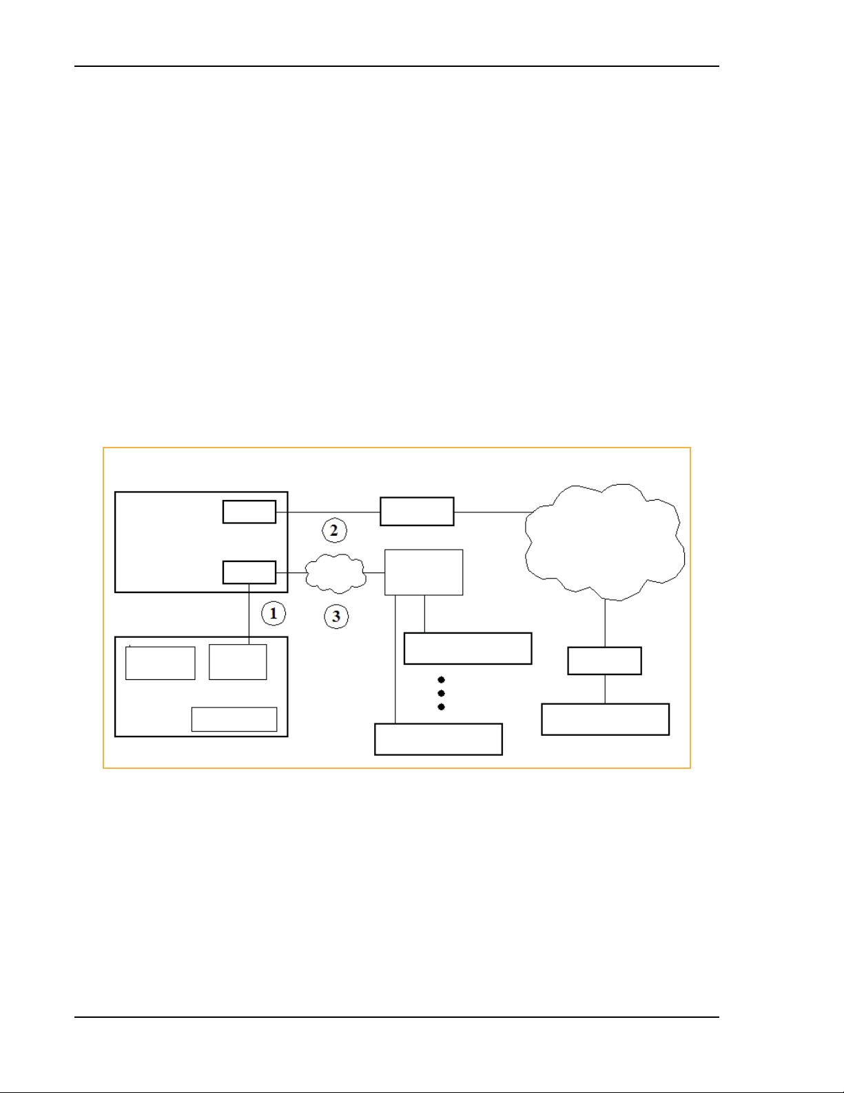
The InterReach Fusion Wideband system consists of three modular components:
• 19" rack-mountable Main Hub
– connects to up to four Expansion Hubs
that supports 1 Expansion Hub)
– conve
– microproc
– auto-configurab
rts RF signals to optical IF on
essor controlled (for alarms, monitoring, and control)
le bands
– simplex interface to RF source
– periodically polls a
ll downstream RAUs for system status, and automatically reports any
fault or warning conditions.
• 19” rack mountable Expansion Hub
– connects to up to eight Remote Access Units
– optical signal conversion to
– microproc
– software c
essor controlled (for alarms, monitoring, and control)
onfigurable band (based on commands from the Main Hub)
– supplies DC power to RAUs ove
electrical on the downlink; electrical to optical on the uplink
r CATV cable.
(except for the One Port Main Hub configuration
the downlink; optical IF-to-RF on the uplink
• Remote Access Uni
– converts IF signals to RF on the d
– microproc
t (RAU)
ownlink; RF-to-IF on the uplink
essor controlled (for alarms, monitoring, and control)
– multi-band protocol independent, frequency specific units.
The min
imum configuration of a Fusion Wideband system is o
ne Main Hub, one Expansion Hub,
and one RAU (1-1-1). The maximum configuration of a system is one Main Hub, four Expansion
Hubs, and 32 RAUs (1-4-32). Multiple systems can be combined to provide larger configurations.
NOTE: The Fusion Wideband One Port Main Hub (PN: FSN-W1-MH-2-1P, FSN-W1-MH-3-1P,
FSN-W2-MH-3-1P, FSN-W3-MH-1P, FSN-W4-MH-1P, and FSN-W5-MH-1P) configuration is a
cost-reduced version of the Fusion Wideband Main Hub and supports only one Expansion Hub
(up to 8 RAUs).
CAUTION! The Fusion Wideband One Port Main Hub is “software locked” to 1 port 2 fiber ports. Additional
rts ar
po
so voids the product warranty.
e disabled internally. Do not attempt to remove the front panel fiber port plate, as doing
Page 8 InterReach Fusion Wideband Installation, Operation, and Reference Manual
© 2015 TE Connectivity D-620616-0-20 Rev K • TECP-77-044 Issue 9 • March 2015
Page 17

Figure 1. Fusion Wideband System Hardware
System Hardware
Figure 2. Fusion Wideband One Port System Hardware
InterReach Fusion Wideband Installation, Operation, and Reference Manual Page 9
D-620616-0-20 Rev K • TECP-77-044 Issue 9 • March 2015 © 2015 TE Connectivity
Page 18
InterReach Fusion Wideband System Description
RS-232
Modem
LAN
Switch
Ethernet
TCP/IP
RS-232
Modem
RJ-45
Ethernet
AdminBrowser
Ethernet
Fusion Wideband
Main Hub
Modem
Fusion Wideband Main Hub
PSTN
Use AdminBrowser to configure or monitor a local or remote Fusion Wideband system.
PC/Laptop running a
Standard Browser
Fusion Wideband
Main Hub
Fusion Wideband
Main Hub
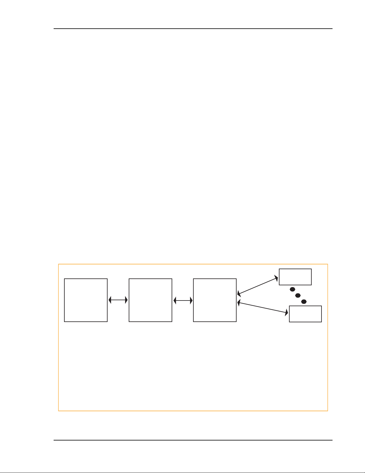
SYSTEM OA&M CAPABILITIES
InterReach Fusion Wideband is microprocessor controlled and contains firmware to enable much
of the operations, administration, and maintenance (OA&M) functionality.
Complete alarming, from each unit
the system (defined as a Fusion Wideband Main Hub and all
in
of its associated Expansion Hubs and Remote Access Units) and the cabling infrastructure is
available. All events occurring in a system are automatically reported to the Main Hub. The Main
Hub monitors system status and communicates that status using the following methods:
• Normally clo
sed (NC) alarm contact closures can be tied to standard NC alarm monitoring
systems or directly to a Base Station (BTS) for basic alarm monitoring.
• Connectio
– Th e Main H ub’s fr ont pan el RJ- 45 port connec ts dir ectly t o a PC
– The Main Hub’s front panel RS-232 serial port conn
n Methods:
(for local Ethernet access).
ects directly to a modem (for remote
access).
– Remote access is also available with an optional 10 0BASE-T LAN switch
connection to the
RJ-45 port.
Page 10 InterReach Fusion Wideband Installation, Operation, and Reference Manual
© 2015 TE Connectivity D-620616-0-20 Rev K • TECP-77-044 Issue 9 • March 2015
Figure 3.
Three Methods for OA&M Communications
Page 19
System OA&M Capabilities
PC/Laptop
running a
standard
web browser
Fusion Wideband
Main Hub
AdminBrowser
Fusion Wideband
Expansion Hub
AdminBrowser
RAU
RAU
Use a standard
browser to communicate
with remotely or locally
installed Fusion Wideband
systems running
AdminBrowser.
If a fault or warning
condition is reported,
the AdminBrowser
graphical user interface
indicates the problem
on your standard PC
browser.
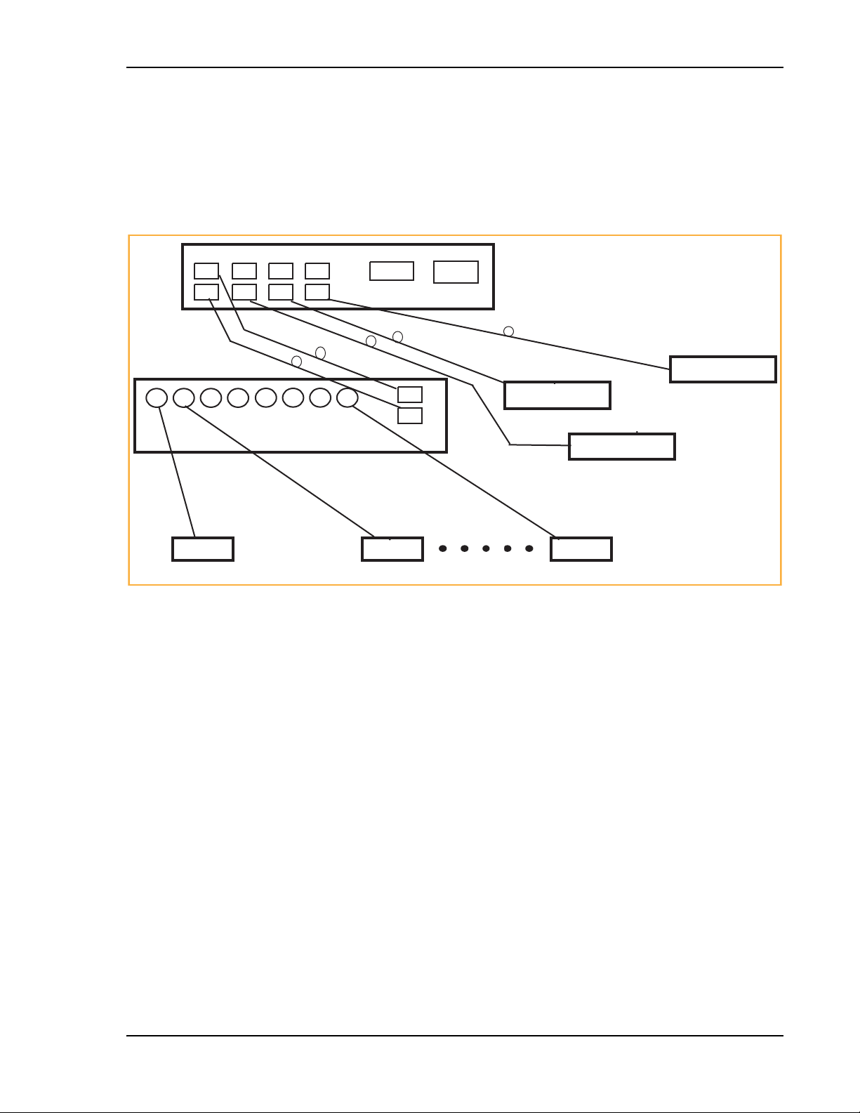
The Main Hub queries status
of each Expansion Hub and
each RAU and compares it
to previously stored
status.
If a fault is detected,
LEDs on the front panel turn
red.
The Expansion Hub queries
the status of each RAU and
compares it to the previously
stored status.
If a fault is detected, LEDs
on the front panel turn red.
Each RAU passes its status to
the Hub.
If a fault is detected, the
Alarm LED is red. If no
fault is detected, the LED
is green.
AdminBrowser OA&M software runs on the Fusion Wideband Main Hub microprocessor and
communicates to its downstream Expansion Hubs and associated RAUs. Using AdminBrowser,
you can perform the following from any standard web browser (such as Internet Explorer)
running on your PC/laptop system:
• configure a newly installed system
• change system parameters
• perform an end-to-end system test
• query system status.
Refer to the AdminBrowser User
Manual (D-620607-0-20) for information about installing and
using the AdminBrowser software.
System Monitoring and Reporting
Each Fusion Wideband Main Hub in the system constantly monitors itself, its Expansion Hubs,
and their downstream RAUs for internal fault and warning conditions. The results of this
monitoring are stored in memory and compared against new results.
f
When a Main or Expansion Hub detects a change in status, it reports a
Faults are also indicated locally by red STATUS LEDs. Both faults and warnings are reported to
the AdminBrowser software and displayed on a PC/laptop connected to the Main Hub’s RJ-45
port. Passive antennas connected to the RAUs are not monitored automatically (perform a System
Test to retrieve status information about antennas).
Using AdminBrowser, you can install a ne
w system or new components, change system
parameters, and query system status. Figure 4 illustrates how the system reports its status to
AdminBrowser.
ault or warning alarm.
InterReach Fusion Wideband Installation, Operation, and Reference Manual Page 11
D-620616-0-20 Rev K • TECP-77-044 Issue 9 • March 2015 © 2015 TE Connectivity
Figure 4.
System Monitoring and Reporting
Page 20

InterReach Fusion Wideband System Description
Using Alarm Contacts
You can connect the DB-9 female connector on the rear panel of the Fusion Wideband Main Hub
to a local BTS or to a daisy-chained series of Fusion and/or FlexWave Focus systems.
When you connect FlexWave Focus or a
BTS to the Fusion Wideband, the Fusion Wideband Main
Hub outputs the alarms (alarm source), and then FlexWave Focus or the BTS receives the alarms
(alarm sense). This is described in “Alarm Source” on page 157
.
Page 12 InterReach Fusion Wideband Installation, Operation, and Reference Manual
© 2015 TE Connectivity D-620616-0-20 Rev K • TECP-77-044 Issue 9 • March 2015
Page 21
System Connectivity
SYSTEM CONNECTIVITY
The double-star architecture of the Fusion Wideband system, illustrated in Figure 5, provides
excellent system scalability and r
antenna points. This makes any system expansion, such as adding an extra antenna for additional
coverage, potentially as easy as pulling an extra CATV cable.
PORT 1 PORT 2 PORT 3 PORT 4
eliability. The system requires only one pair of fibers for eight
RS-232 RJ-45
Main Hub
Fiber
Expansion Hub
Expansion Hub
Expansion Hub
CATV (RG-59, 6, or 11)
RAU RAU RAU
Figure 5.
CATV
Up to 8 RAUs per Expansion Hub
Fusion Wideband’s Double Star Architecture
Expansion Hub
CATV
InterReach Fusion Wideband Installation, Operation, and Reference Manual Page 13
D-620616-0-20 Rev K • TECP-77-044 Issue 9 • March 2015 © 2015 TE Connectivity
Page 22
InterReach Fusion Wideband System Description
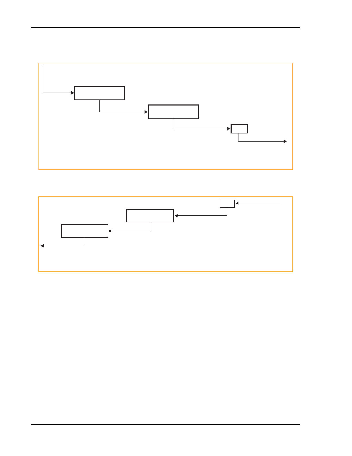
SYSTEM OPERATION
The Main Hub receives downlink
RF signals from a base station using
50 Ohm coaxial cable.
The Main Hub converts the RF signals to IF, then
Main Hub
to optical signals and sends them to Expansion
Hubs (up to four) using optical fiber cable.
Expansion Hub
The Expansion Hub converts the optical signals
to electrical signals and sends them to RAUs
(up to eight) using 75 Ohm CATV cable.
Figure 6. Downlink (BTS to Wireless Devices)
RAU
The RAU converts the IF signals
to RF and sends them to passive
antennas using 50 Ohm coaxial
cable.
Main Hub
The Main Hub sends
uplink RF signals to a
base station using
50 Ohm coaxial cable.
Expansion Hub
The Main Hub receives
the optical signals from
the Expansion Hubs (up
to four) using optical fiber
cable and con-verts them
to RF sig-nals.
The Expansion Hub receives
the IF signals from the RAUs
(up to eight) using CATV cable
and converts them to optical
signals.
Figure 7. Uplink (Wireless Devices to BTS)
RAU
The RAU receives uplink
RF signals from the
passive antenna using
50 Ohm coaxial cable and
converts them to IF signals.
Page 14 InterReach Fusion Wideband Installation, Operation, and Reference Manual
© 2015 TE Connectivity D-620616-0-20 Rev K • TECP-77-044 Issue 9 • March 2015
Page 23

SYSTEM SPECIFICATIONS
Table 1. Physical Specifications
Parameter Main Hub Expansion Hub Remote Access Unit
(a)
IF/RF Connectors 4-type “N” female
(50 Ohm),
1 Downlink/Uplink pair per
d
ban
External Alarm Connector
One, 9-pin D-sub, female One, 9-pin D-sub, female —
(contact source)
ADMIN/LAN Interface
Connectors
One RJ-45, female
One 9-pin D-sub, male for
optional modem
Fiber Connectors
LED Alarm and Status
Indicators
(c)
4 pair, SC/APC
Unit Status (One pair):
•Power
ain Hub Status
• M
Downstream Unit Status
(One per fiber port):
• Expansion Hub/RAU
Power (AC Option) Rating: 100–240V AC, 1A,
0–60
Hz
5
Operating Range: 90–132V
AC/170-250V
AC auto-
ranging
Power (DC Option) Rating: 38–64V DC, 2.5A Rating: 38-64V DC, 14A
Power Consumption (W) 30 4 RAUs: 290 typical, 360 max.
(e)
Enclosure Dimensions
(height ´ width ´ depth)
89 mm × 438 mm × 381 mm
(3.5 in. × 17.25 in. × 15 in.)
2U
Weight < 5.5 kg (< 12 lbs.) < 6.6 kg (< 14.5 lbs.) < 2.1 kg (< 4.6 lbs.)
a 6-type N, female connectors for FSN-W2-MH-1, FSN-W2-MH-3, FSN-W4-MH-1, and FSN-W5-MH-1 Main Hub.
b 2-type N, female connectors for FSN-W1-1921-1, FSN-W2-80851
FSN-W4-702121-1-HP, FSN-W4-752121-1-HP, FSN-W5-851921-1-HP, and FSN-2525-1-TDD RAUs.
c It is critical to system performance that
panels.
d FSN-W1-MH-2-1P, FSN-W1-MH-3-1P, FSN-W2-MH-3-1P, FSN-W3-MH-1P,
SP/APC fibers.
e Excluding angle-brackets for
19'' rack hub mounting of the hub.
only
8-type “F”, female
(CATV 75 Ohm)
One F, female (CATV -75 Ohm)
One N, female
(b)
(antenna-50 Ohm)
One RJ-45, female
—
One 9-pin D-sub, male
(d)
One pair, SC/APC —
Unit Status (One pair):
•Power
Expansion Hub Status
•
Unit Status (One pair):
•Link
•Al
arm
Fiber Link Status (One pair):
•DL Status
L
Status
•U
Port Status:
• One per F connector port
i
nk/RAU
•L
Rating: 100–240V AC, 6A,
–60
Hz
50
—
Operating Range: 90–132V
AC/170-250V AC
ranging
auto-
—
8 RAUs: 500 typical, 630 Max.
89 mm × 438 mm × 381 mm
(3.5 in. × 17.25 in. × 15 in.)
54 mm x 286 mm x 281 mm
(2.13 in. × 11.25 in. × 11.13 in.)
2U
9-1, FSN-W2-7575-1, FSN-W2-7070-1, FSN-W3-2626-1,
SC/APC fiber connectors are used throughout the fiber network, including fiber distribution
FSN-W4-MH-1P, and FSN-W5-MH-1P support only one pair,
System Specifications
NOTE: Note: The Fusion Wideband Main Hub’s typical power consumption assumes that the CATV
RG-59 cable length is no more than 130 meters, the RG-6 cable length is no more than 140
meters, and RG-11 cable length is no more than 235 meters using CommScope 2065V, 2279V, and
2293K cables.
InterReach Fusion Wideband Installation, Operation, and Reference Manual Page 15
D-620616-0-20 Rev K • TECP-77-044 Issue 9 • March 2015 © 2015 TE Connectivity
Page 24

InterReach Fusion Wideband System Description
Table 2. Wavelength and Laser Power Specifications
Measured Output Power
Wavelength Main Hub Expansion Hub
1310 nm
+20 nm 890 uW 3.8 mW
Table 3. Environmental Specifications
Parameter Main Hub and Expansion Hub RAU
Operating Temperature 0° to +45°C (+32° to +113°F) –25° to +45°C (–13° to +113°F)
Non-operating Temperature –20° to +85°C (–4° to +185°F) –25° to +85°C (–13° to +185°F)
Operating Humidity; non-condensing 5% to 95% 5% to 95%
Table 4. Frequency Bands Covered by Fusion Wideband RAUs
Fusion RAU Part Number Fusion
2100/1800 FSN-W1-2118-1 2100 2110-2170 1920-1980 1 60 MHz
2100 HP/1800 HP FSN-W1-2118-1-HP 1800 1805-1880 1710-1785 2 75 MHz
2100 HP/2600 HP FSN-W1-2126-1-HP 2100 2110-2170 1920-1980 1 60 MHz
2100 High Power
(single-band RAU)
1900/AWS FSN-W1-1921-1 1900 (A-F) 1930-1990 1850-1910 1 60 MHz
800/850/1900 FSN-W2-808519-1 800 851-869 806-824 1
700/AWS FSN-W2-7021-1 700 (Upper C) 746-757 776-787 1
700/700 MIMO
(Upper C)
700/700 MIMO
(Lower ABC)
FSN-W1-21HP-1 2100 2110-2170 1920-1980 1 60 MHz
FSN-W2-7575-1 700 (Upper C) 746-757 776-787 1
FSN-W2-7070-1 700
Band
2600 2620-2690 2500-2570 2 70 MHz
AWS 2110-2155 1710-1755 2 45 MHz
850 869-894 824-849 3
1900 (A - F) 1930-1990 1850-1910 2 60 MHz
700
(Lower ABC)
AWS 2110-2155 1710-1755 2 45 MHz
700 (Upper C) 746-757 776-787 3
(Lower ABC)
700
(Lower ABC)
Downlink (MHz) Uplink (MHz) MAIN HUB/
728-746 698-716 3
728-746 698-716 1
728-746 698-716 3
RF Passband
RAU Band
(sub-band 1A)
(sub-band 1B)
(sub-band 1A)
(sub-band 1B)
(sub-band 1A)
(sub-band 1B)
(sub-band 1A)
(sub-band 1B)
RAU
Bandwidth
18 MHz
25 MHz
11 MHz
18 MHz
11 MHz
11 MHz
18 MHz
18 MHz
Page 16 InterReach Fusion Wideband Installation, Operation, and Reference Manual
© 2015 TE Connectivity D-620616-0-20 Rev K • TECP-77-044 Issue 9 • March 2015
Page 25

Table 4. Frequency Bands Covered by Fusion Wideband RAUs (Cont.)
System Specifications
Fusion RAU Part Number Fusion
RF Passband
Band
700 ABC/AWS HP/
AWS HP
Downlink (MHz) Uplink (MHz) MAIN HUB/
FSN-W4-702121-1-HPAWS 2110-2155 1710-1755 1
700
728-746 698-716 3
(Lower ABC)
RAU Band
(sub-band 1A)
(sub-band 1B)
RAU
Bandwidth
45 MHz
18 MHz
AWS 2110-2155 1710-1755 2 45 MHz
700 UC/AWS HP/
AWS HP
FSN-W4-752121-1-HPAWS 2110-2155 1710-1755 1
700 (Upper C) 746-757 776-787 3
45 MHz
(sub-band 1A)
11 MHz
(sub-band 1B)
AWS 2110-2155 1710-1755 2 45 MHz
850/1900 HP/
AWS HP
FSN-W5-851921-1-HPAWS 2110-2155 1710-1755 1
850 869-894 824-849 3
45 MHz
(sub-band 1A)
25 MHz
(sub-band 1B)
1900 (A - G) 1930-1995 1850-1915 2 65 MHz
2500/2500 FSN-2525-1-TDD 2500 2496-2690 2496-2690 1 66 MHz
2500 2496-2690 2496-2690 2 66 MHz
2600/2600 FSN-W3-2626-1 2600 2620-2690 2500-2570 1 70 MHz
2600 2620-2690 2500-2570 2 70 MHz
InterReach Fusion Wideband Installation, Operation, and Reference Manual Page 17
D-620616-0-20 Rev K • TECP-77-044 Issue 9 • March 2015 © 2015 TE Connectivity
Page 26

InterReach Fusion Wideband System Description
RF END-TO-END PERFORMANCE
The following tables list the RF end-to-end performance for each protocol.
NOTE: The system gain is adjustable in 1 dB steps from 0 to 15 dB, and the gain of each RAU can be
attenuated at 0 or 10 dB.
2100/1800 RAU (FSN-W1-2118-1)
Table 5. 2100 MHz RF End-to-End Performance
Parameter
Average gain with 130 m RG-59 at 25°C (77°F) (dB) 15 15
Ripple with 130 m RG-59 (dB) 4.5 4.5
Output IP3 (dBm) 38
Input IP3 (dBm) -5
Output 1 dB Compression Point (dBm) 26
Noise Figure 1 MH, 1 EH, 8 RAUs (dB) 17
Noise Figure 1 MH, 4 EH, 32 RAUs (dB) 23
Typical
Downlink Uplink
Table 6. 1800 MHz RF End-to-End Performance
Parameter
Average gain with 130 m RG-59 at 25°C (77°F) (dB) 15 15
Ripple with 130 m RG-59 (dB) 4.5 4.5
Output IP3 (dBm) 38
Input IP3 (dBm) –5
Output 1 dB Compression Point (dBm) 26
Noise Figure 1 MH, 1 EH, 8 RAUs (dB) 17
Noise Figure 1 MH, 4 EH, 32 RAUs (dB) 23
Typical
Downlink Uplink
Page 18 InterReach Fusion Wideband Installation, Operation, and Reference Manual
© 2015 TE Connectivity D-620616-0-20 Rev K • TECP-77-044 Issue 9 • March 2015
Page 27

2100 HP/1800 HP (FSN-W1-2118-1-HP)
Table 7. 2100 MHz RF End-to-End Performance
RF End-to-End Performance
Parameter
Average gain with 130 m RG-59 at 25°C (77°F) (dB) 20 15
Ripple with 130 m RG-59 (dB) 4.5 4.5
Output IP3 (dBm) 42
Input IP3 (dBm) -5
Output 1 dB Compression Point (dBm) 30
Noise Figure 1 MH, 1 EH, 8 RAUs (dB) 17
Noise Figure 1 MH, 4 EH, 32 RAUs (dB) 23
Typical
Downlink Uplink
Table 8. 1800 MHz RF End-to-End Performance
Parameter
Average gain with 130 m RG-59 at 25°C (77°F) (dB) 18 15
Ripple with 130 m RG-59 (dB) 4.5 4.5
Output IP3 (dBm) 42
Input IP3 (dBm) –5
Output 1 dB Compression Point (dBm) 30
Noise Figure 1 MH, 1 EH, 8 RAUs (dB) 17
Noise Figure 1 MH, 4 EH, 32 RAUs (dB) 23
Typical
Downlink Uplink
InterReach Fusion Wideband Installation, Operation, and Reference Manual Page 19
D-620616-0-20 Rev K • TECP-77-044 Issue 9 • March 2015 © 2015 TE Connectivity
Page 28

InterReach Fusion Wideband System Description
2100 HP/2600 HP (FSN-W1-2126-1-HP)
Table 9. 2100 MHz RF End-to-End Performance
Parameter
Average gain with 130 m RG-59 at 25°C (77°F) (dB) 20 15
Ripple with 130 m RG-59 (dB) 4.5 4.5
Output IP3 (dBm) 42
Input IP3 (dBm) -5
Output 1 dB Compression Point (dBm) 30
Noise Figure 1 MH, 1 EH, 8 RAUs (dB) 17
Noise Figure 1 MH, 4 EH, 32 RAUs (dB) 23
Typical
Downlink Uplink
Table 10. 2600 MHz RF End-to-End Performance
Parameter
Average gain with 130 m RG-59 at 25°C (77°F) (dB) 20 15
Ripple with 130 m RG-59 (dB) 4.5 4.5
Output IP3 (dBm) 42
Input IP3 (dBm) –5
Output 1 dB Compression Point (dBm) 30
Noise Figure 1 MH, 1 EH, 8 RAUs (dB) 17
Noise Figure 1 MH, 4 EH, 32 RAUs (dB) 23
Typical
Downlink Uplink
2100 High Power RAU (FSN-W1-21HP-1)
Table 11. 2100 MHz High Power RF End-to-End Performance
Parameter
a,b
Average gain with 130 m RG-59 at 25°C (77°F) (dB)
Ripple with 130 m RG-59 (dB) 4.5 5
Output IP3 (dBm) 44
Input IP3 (dBm) –5
Output 1 dB Compression Point (dBm) 33
Noise Figure 1 MH, 1 EH, 8 RAUs (dB) 17
Noise Figure 1 MH, 4 EH, 32 RAUs (dB) 23
a The system Downlink gain is adjustable in
High Power RAU adds 7 dB of Downlink gain).
b The system Uplink gain is adjustable in 1 dB steps from 0 to 15 dB.
Page 20 InterReach Fusion Wideband Installation, Operation, and Reference Manual
© 2015 TE Connectivity D-620616-0-20 Rev K • TECP-77-044 Issue 9 • March 2015
1 dB
22 15
steps from 7 to 22 dB (the
Typical
Downlink Uplink
Page 29

1900/AWS RAU (FSN-W1-1921-1)
Table 12. 1900 MHz RF End-to-End Performance
RF End-to-End Performance
Parameter
Average gain with 130 m RG-59 at 25°C (77°F) (dB) 15 15
Ripple with 130 m RG-59 (dB) 3.5 4
Output IP3 (dBm) 38
Input IP3 (dBm) –5
Output 1 dB Compression Point (dBm) 26
Noise Figure 1 MH, 1 EH, 8 RAUs (dB) 17
Noise Figure 1 MH, 4 EH, 32 RAUs (dB) 23
Typical
Downlink Uplink
Table 13. AWS RF End-to-End Performance
Parameter
Average gain with 130 m RG-59 at 25°C (77°F) (dB) 15 15
Ripple with 130 m RG-59 (dB) 3.5 4
Output IP3 (dBm) 38
Input IP3 (dBm) –5
Output 1 dB Compression Point (dBm) 26
Noise Figure 1 MH, 1 EH, 8 RAUs (dB) 17
Noise Figure 1 MH, 4 EH, 32 RAUs (dB) 23
Typical
Downlink Uplink
InterReach Fusion Wideband Installation, Operation, and Reference Manual Page 21
D-620616-0-20 Rev K • TECP-77-044 Issue 9 • March 2015 © 2015 TE Connectivity
Page 30

InterReach Fusion Wideband System Description
800/850/1900 RAU (FSN-W2-808519-1)
Table 14. 800 MHz RF End-to-End Performance
Parameter
Average gain with 130 m RG-59 at 25°C (77°F) (dB) 15 15
Ripple with 130 m RG-59 (dB) 2.5 3
Output IP3 (dBm) 37
Input IP3 (dBm) –5
Output 1 dB Compression Point (dBm) 25
Noise Figure 1 MH, 1 EH, 8 RAUs (dB) 17
Noise Figure 1 MH, 4 EH, 32 RAUs (dB) 23
Typical
Downlink Uplink
Table 15. 850 MHz RF End-to-End Performance
Parameter
Average gain with 130 m RG-59 at 25°C (77°F) (dB) 15 15
Ripple with 130 m RG-59 (dB) 2.5 3
Output IP3 (dBm) 37
Input IP3 (dBm) –5
Output 1 dB Compression Point (dBm) 25
Noise Figure 1 MH, 1 EH, 8 RAUs (dB) 17
Noise Figure 1 MH, 4 EH, 32 RAUs (dB) 23
Typical
Downlink Uplink
Table 16. 1900 MHz RF End-to-End Performance
Parameter
Average gain with 130 m RG-59 at 25°C (77°F) (dB) 15 15
Ripple with 130 m RG-59 (dB) 3.5 4
Output IP3 (dBm) 38
Input IP3 (dBm) –5
Output 1 dB Compression Point (dBm) 26
Noise Figure 1 MH, 1 EH, 8 RAUs (dB) 17
Noise Figure 1 MH, 4 EH, 32 RAUs (dB) 23
Page 22 InterReach Fusion Wideband Installation, Operation, and Reference Manual
© 2015 TE Connectivity D-620616-0-20 Rev K • TECP-77-044 Issue 9 • March 2015
Typical
Downlink Uplink
Page 31

700/AWS RAU (FSN-W2-7021-1)
Table 17. 700 MHz (Lower ABC) RF End-to-End Performance
RF End-to-End Performance
Parameter
Average gain with 130 m RG-59 at 25°C (77°F) (dB) 15 15
Ripple with 130 m RG-59 (dB) 2.5 3
Output IP3 (dBm) 34
Input IP3 (dBm) –5
Output 1 dB Compression Point (dBm) 22
Noise Figure 1 MH, 1 EH, 8 RAUs (dB) 20
Noise Figure 1 MH, 4 EH, 32 RAUs (dB) 26
Typical
Downlink Uplink
Table 18. 700 MHz (Upper C) RF End-to-End Performance
Parameter
Average gain with 130 m RG-59 at 25°C (77°F) (dB) 15 15
Ripple with 130 m RG-59 (dB) 2.5 3
Output IP3 (dBm) 34
Input IP3 (dBm) –5
Output 1 dB Compression Point (dBm) 22
Noise Figure 1 MH, 1 EH, 8 RAUs (dB) 20
Noise Figure 1 MH, 4 EH, 32 RAUs (dB) 26
Typical
Downlink Uplink
Table 19. AWS RF End-to-End Performance
Parameter
Average gain with 130 m RG-59 at 25°C (77°F) (dB) 15 15
Ripple with 130 m RG-59 (dB) 3.5 4
Output IP3 (dBm) 38
Input IP3 (dBm) –5
Output 1 dB Compression Point (dBm) 26
Noise Figure 1 MH, 1 EH, 8 RAUs (dB) 17
Noise Figure 1 MH, 4 EH, 32 RAUs (dB) 23
InterReach Fusion Wideband Installation, Operation, and Reference Manual Page 23
D-620616-0-20 Rev K • TECP-77-044 Issue 9 • March 2015 © 2015 TE Connectivity
Typical
Downlink Uplink
Page 32

InterReach Fusion Wideband System Description
700/700 (Upper C) MIMO RAU (FSN-W2-7575-1)
Table 20. 700 MHz (Upper C) RF End-to-End Performance
Parameter
Average gain with 130 m RG-59 at 25°C (77°F) (dB) 15 15
Ripple with 130 m RG-59 (dB) 2.5 3
Output IP3 (dBm) 38
Input IP3 (dBm) –5
Output 1 dB Compression Point (dBm) 26
Noise Figure 1 MH, 1 EH, 8 RAUs (dB) 17
Noise Figure 1 MH, 4 EH, 32 RAUs (dB) 23
700/700 (Lower ABC) MIMO RAU (FSN-W2-7070-1)
Table 21. 700 MHz (Lower ABC) RF End-to-End Performance
Parameter
Average gain with 130 m RG-59 at 25°C (77°F) (dB) 15 15
Ripple with 130 m RG-59 (dB) 2.5 3
Output IP3 (dBm) 38
Input IP3 (dBm) –5
Output 1 dB Compression Point (dBm) 26
Noise Figure 1 MH, 1 EH, 8 RAUs (dB) 17
Noise Figure 1 MH, 4 EH, 32 RAUs (dB) 23
Typical
Downlink Uplink
Typical
Downlink Uplink
Page 24 InterReach Fusion Wideband Installation, Operation, and Reference Manual
© 2015 TE Connectivity D-620616-0-20 Rev K • TECP-77-044 Issue 9 • March 2015
Page 33

700 ABC/AWS HP/AWS HP RAU (FSN-W4-702121-1-HP)
Table 22. 700 MHz (Lower ABC) RF End-to-End Performance
RF End-to-End Performance
Parameter
Average gain with 130 m RG-59 at 25°C (77°F) (dB) 15 15
Ripple with 130 m RG-59 (dB) 2.5 3
Output IP3 (dBm) 38
Input IP3 (dBm) –5
Output 1 dB Compression Point (dBm) 26
Noise Figure 1 MH, 1 EH, 8 RAUs (dB) 16
Noise Figure 1 MH, 4 EH, 32 RAUs (dB) 22
Typical
Downlink Uplink
Table 23. AWS RF End-to-End Performance
Parameter
Average gain with 130 m RG-59 at 25°C (77°F) (dB) 20 15
Ripple with 130 m RG-59 (dB) 3.5 4
Output IP3 (dBm) 43
Input IP3 (dBm) –5
Output 1 dB Compression Point (dBm) 31
Noise Figure 1 MH, 1 EH, 8 RAUs (dB) 17
Noise Figure 1 MH, 4 EH, 32 RAUs (dB) 23
Typical
Downlink Uplink
InterReach Fusion Wideband Installation, Operation, and Reference Manual Page 25
D-620616-0-20 Rev K • TECP-77-044 Issue 9 • March 2015 © 2015 TE Connectivity
Page 34

InterReach Fusion Wideband System Description
700 UC/AWS HP/AWS HP RAU (FSN-W4-752121-1-HP)
Table 24. 700 MHz (Upper C) RF End-to-End Performance
Parameter
Average gain with 130 m RG-59 at 25°C (77°F) (dB) 15 15
Ripple with 130 m RG-59 (dB) 2.5 3
Output IP3 (dBm) 38
Input IP3 (dBm) –5
Output 1 dB Compression Point (dBm) 26
Noise Figure 1 MH, 1 EH, 8 RAUs (dB) 16
Noise Figure 1 MH, 4 EH, 32 RAUs (dB) 22
Typical
Downlink Uplink
Table 25. AWS RF End-to-End Performance
Parameter
Average gain with 130 m RG-59 at 25°C (77°F) (dB) 20 15
Ripple with 130 m RG-59 (dB) 3.5 4
Output IP3 (dBm) 43
Input IP3 (dBm) –5
Output 1 dB Compression Point (dBm) 31
Noise Figure 1 MH, 1 EH, 8 RAUs (dB) 17
Noise Figure 1 MH, 4 EH, 32 RAUs (dB) 23
Typical
Downlink Uplink
Page 26 InterReach Fusion Wideband Installation, Operation, and Reference Manual
© 2015 TE Connectivity D-620616-0-20 Rev K • TECP-77-044 Issue 9 • March 2015
Page 35

850/1900 HP/AWS HP RAU (FSN-W5-851921-1-HP)
Table 26. 850 MHz RF End-to-End Performance
RF End-to-End Performance
Parameter
Average gain with 130 m RG-59 at 25°C (77°F) (dB) 15 15
Ripple with 130 m RG-59 (dB) 2.5 3
Output IP3 (dBm) 38
Input IP3 (dBm) –5
Output 1 dB Compression Point (dBm) 26
Noise Figure 1 MH, 1 EH, 8 RAUs (dB) 16
Noise Figure 1 MH, 4 EH, 32 RAUs (dB) 22
Typical
Downlink Uplink
Table 27. 1900 MHz RF End-to-End Performance
Parameter
Average gain with 130 m RG-59 at 25°C (77°F) (dB) 20 15
Ripple with 130 m RG-59 (dB) 3.5 4
Output IP3 (dBm) 43
Input IP3 (dBm) –5
Output 1 dB Compression Point (dBm) 31
Noise Figure 1 MH, 1 EH, 8 RAUs (dB) 17
Noise Figure 1 MH, 4 EH, 32 RAUs (dB) 23
Typical
Downlink Uplink
Table 28. AWS RF End-to-End Performance
Parameter
Average gain with 130 m RG-59 at 25°C (77°F) (dB) 20 15
Ripple with 130 m RG-59 (dB) 3.5 4
Output IP3 (dBm) 43
Input IP3 (dBm) –5
Output 1 dB Compression Point (dBm) 31
Noise Figure 1 MH, 1 EH, 8 RAUs (dB) 17
Noise Figure 1 MH, 4 EH, 32 RAUs (dB) 23
InterReach Fusion Wideband Installation, Operation, and Reference Manual Page 27
D-620616-0-20 Rev K • TECP-77-044 Issue 9 • March 2015 © 2015 TE Connectivity
Typical
Downlink Uplink
Page 36

InterReach Fusion Wideband System Description
2500/2500 RAU (FSN-2525-1-TDD)
Table 29. 2500 MHz TDD RF End-to-End Performance
Parameter
Average gain with 130 m RG-59 at 25°C (77°F) (dB) 20 15
Ripple with 130 m RG-59 (dB) 5.0 5.0
Output IP3 (dBm) 42.5
Input IP3 (dBm) –5
Output 1 dB Compression Point (dBm) 32
Noise Figure 1 MH, 1 EH, 8 RAUs (dB) 17
Noise Figure 1 MH, 4 EH, 32 RAUs (dB) 23
2600/2600 RAU (FSN-W3-2626-1)
Table 30. 2600 MHz RF End-to-End Performance
Parameter
Average gain with 130 m RG-59 at 25°C (77°F) (dB) 15 15
Ripple with 130 m RG-59 (dB) 4.5 5
Output IP3 (dBm) 38
Input IP3 (dBm) –5
Output 1 dB Compression Point (dBm) 26
Noise Figure 1 MH, 1 EH, 8 RAUs (dB) 17
Noise Figure 1 MH, 4 EH, 32 RAUs (dB) 23
Typical
Downlink Uplink
Typical
Downlink Uplink
Page 28 InterReach Fusion Wideband Installation, Operation, and Reference Manual
© 2015 TE Connectivity D-620616-0-20 Rev K • TECP-77-044 Issue 9 • March 2015
Page 37

FUSION WIDEBAND MAIN HUB
Topics Page
Fusion Wideband Main Hub Overview................................................................................................................................... 30
Fusion Wideband Main Hub Front Panel
Uplink/Downlink Optical-Fiber Ports..................................................................................................
Main Hub LED Indicators ..........................................................................................................................................................33
Unit STATUS LEDs .............................................................................................................................................................34
Fiber Port LEDs .......................................................................................................................
Communications RS-232 Serial Connector ...............................................................................................................................35
Fusion Wideband Main Hub Rear Panel...................................................................................................................................36
Main Hub Specifications ........................................................................................................................................................ 37
Faults, Warnings, and Status Mess
Events .......................................................................................................................................................................................38
View Alarm Preferences ..............................................................................................................
................................................................................................................................ 32
......................................33
..........................................35
ages.................................................................................................................................. 38
.............................................39
InterReach Fusion Wideband Installation, Operation, and Reference Manual Page 29
D-620616-0-20 Rev H • TECP-77-044 Issue 9 • March 2015 ©2015 TE Connectivity
Page 38

Fusion Wideband Main Hub
Downlink Path: The Main Hub receives up to 3 individual (Band1, 2, or 3) downlink RF signals from a base station, repeater,
or FlexWave Focus system using 50 Ohm coaxial cable. It converts the signals to IF then to optical and sends them to up to
four Expansion Hubs using fiber optic cable.
The Main Hub also sends OA&M communication to the Expansion Hubs using the fiber optic cable. The Expansion Hubs,
in turn, communicate the OA&M information to the RAUs using CATV cable.
Uplink Path: The Main Hub receives uplink optical signals from up to four Expansion Hubs using fiber optic cables. It converts
the signals to IF then to RF and sends them to the respective Band1, 2, or 3 base station, repeater, or FlexWave Focus system
using 50 Ohm coaxial cable.
The Main Hub also receives status information from the Expansion Hubs and all RAUs using the fiber optic cable.
RF1, 2, and 3
Downlink to Main Hub
Uplink from Main Hub
RF1, 2, and 3
Downlink to Main Hub
Uplink from Main Hub
Fusion Wideband
Main Hub
Fusion Wideband
Main Hub
RAU
FUSION WIDEBAND MAIN HUB OVERVIEW
The Fusion Wideband Main Hub (shown in Figure 8) distributes up to three individual (Band 1, 2,
and 3) downlink RF signals from a Base
Expansion Hubs, which in turn distribute the signals to up to 32 Remote Access Units. The Main
Hub also combines uplink signals from the associated Expansion Hubs.
Fusion Wideband is a multi-band sy
and the other RF source (Band 2 or RF2) goes to the 75 MHz band. Band 3 (or RF3) goes to a 25
MHz sub-band of the 60 MHz band and is functional only with the following RAUs:
800/850/1900, 700/AWS, 700/700 (Upper C) MIMO, 700/700 (Lower ABC) MIMO, 700
ABC/AWS HP/AWS HP, 700 UC/AWS HP/AWS HP, and 850/1900 HP/AWS HP RAU. The system
installs in a 19”equipment rack and is usually co-located with the RF source in a
telecommunications closet.
Station, repeater, or FlexWave Focus system to up to four
s
tem. One RF source (Band 1 or RF1) go es to th e 60 MHz ban d
Figure 8.
Main Hub in a Fusion Wideband System
Figure 9 on page 31 shows a detailed view of the major RF and optical functional blocks of the
Main Hub.
NOTE: The Fusion Wideband One Port Main Hub (PNs: FSN-W1-MH-2-1P, FSN-W2-MH-3-1P,
Page 30 InterReach Fusion Wideband Installation, Operation, and Reference Manual
© 2015 TE Connectivity D-620616-0-20 Rev K • TECP-77-044 Issue 9 • March 2015
FSN-W3-MH-1P, FSN-W4-MH-1P, and FSN-W5-MH-1P) is a cost reduced version of the Fusion
Wideband Main Hub and supports only one Expansion Hub (up to 8 RAUs).
Page 39

Fusion Wideband Main Hub Overview
Downlink
RF In
Band 1
Downlink
RF In
Band 2
Downlink
RF In
Band 3
Uplink
RF Out
Band 1
Uplink
RF Out
Band 2
Uplink
RF Out
Band 3
RF to IF
Section B1
RF to IF
Section B2
RF to IF
Section B3
CAL Tone
IF to RF
Section B1
IF to RF
Section B2
IF to RF
Section B3
Diplexer
Diplexer
i
IF Section IF to Optical
Clock,
FSK,
Pilot
Micro FSK
IF
Section
Piolt Det,
FSK
Combiner
Optical
Splitter
Optical to IF
Optical to IF
Optical to IF
Optical to IF
Downlink
Optical
OUT
Uplink
Optical
Input
Power Supply
Single-Board Computer
Figure 9. Main Hub Block Diagram
Alarm
Interface
Alarm
InterReach Fusion Wideband Installation, Operation, and Reference Manual Page 31
D-620616-0-20 Rev K • TECP-77-044 Issue 9 • March 2015 © 2015 TE Connectivity
Page 40
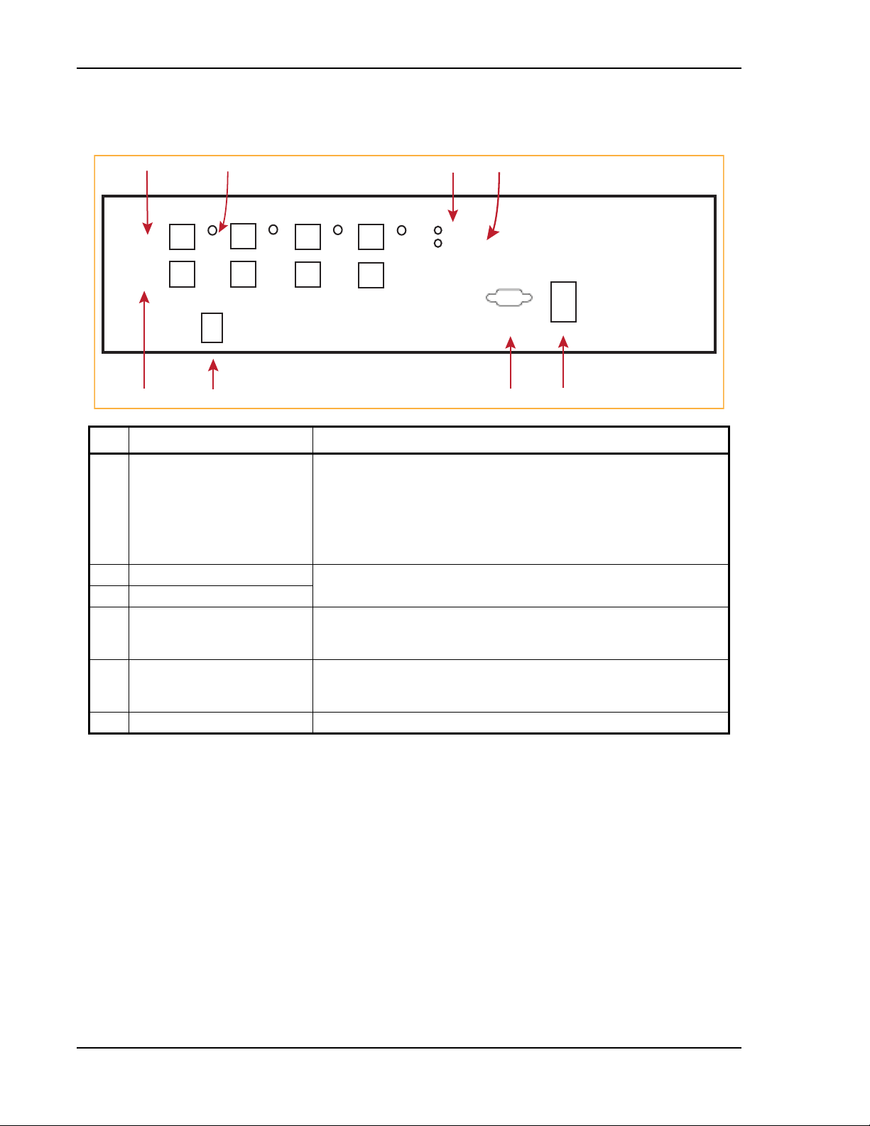
Fusion Wideband Main Hub
POWER
MAIN HUB
STATUS
UPLINK
DOWNLINK
PORT 1
PORT 2
PORT 3
PORT 4
POWER
InterReach
Wideband Fusion
Main Hub
ADMIN LANMODEM
1
3
567
Unit is not shown to scale.
2
4
8
FUSION WIDEBAND MAIN HUB FRONT PANEL
Ref # Component Function
Port 1 - Port 4 Four fiber optic ports with corresponding
1, 8 UPLINK and DOWNLINK ports One standard female SC/APC connector per port for MMF/SMF inpu
and one standard female SC/APC connector per port for MMF/SMF output
(DOWNLINK). See “Uplink/Downlink Optical-Fiber Ports” on page 33
2 STATUS LED (unlabeled) One LED per port for port link status and downstream unit status
LEDs” on page 35.
3 POWER LED See “Main Hub LED Indicators” on page 33.
4 MAIN HUB STATUS LED
5 ADMIN/LAN connector One RJ-45 female connector for system communication and diagnostics u
PC/laptop with direct connect or using a LAN switch; see “Communications
RS-232 Serial Connector” on page 35.
6 Modem connector One 9-pin D-sub male connector for system
diagnostics using a modem; see “Communications RS-232 Serial Connector” on
page 35.
7 Power switch Turns the Fusion Wideband Main Hub on or off.
fiber port LEDs (one LED per port)
t (UPLINK)
.
; see “Fiber Port
sing a
remote dial-
up communication and
Page 32 InterReach Fusion Wideband Installation, Operation, and Reference Manual
© 2015 TE Connectivity D-620616-0-20 Rev K • TECP-77-044 Issue 9 • March 2015
Page 41

Fusion Wideband Main Hub Front Panel
Uplink/Downlink Optical-Fiber Ports
The uplink/downlink optical-fiber ports transmit and receive optical signals between the Main
Hub and up to four Expansion Hubs using industry-standard SMF or MMF cable. There are four
fiber ports on the front panel of the Main Hub—one port per Expansion Hub. Each optical-fiber
port has two female SC/APC connectors:
• UPLINK Co
• DOWNLINK Connector—transmits the dow
CAUTION! To avoid damaging the Main Hub’s fiber connector ports, use only SC/APC fiber cable connectors
nnector—receives the uplink optical signals from an Expansion Hub.
nlink optical signals to an Expansion Hub.
when using either single-mode or multi-mode fiber. Additionally, it is critical to system
performance that only SC/APC fiber connectors are used throughout the fiber network, including
fiber distribution panels.
Main Hub LED Indicators
The unit’s front panel LEDs indicate faults and commanded or fault lockouts. The LEDs do not
indicate warnings or whether the system test has been performed. Use the LEDs to provide basic
information only, or as a backup when you are not using AdminBrowser.
Upon power up, the Main Hub goes through a 20-second test to check the
time, the LEDs blink through the states shown in Table 31 on page 34, letting you visually verify
hat the LED lamps and the firmware are functioning properly. Upon
t
the LEDs stay in one of the first two states shown in Table 31 on page 34.
The Main Hub automatically sends the
program
bands command to all connected RAUs. A
mismatched band causes a fault message to be displayed in AdminBrowser and places the RAU in
a disabled condition.
LED lamps. During this
completion of initialization,
NOTE: Refer to “Troubleshooting Using LEDs” on page 185 for troubleshooting using the LEDs.
NOTE: AdminBrowser should be used for troubleshooting the system. Only use LEDs for backup or
confirmation. However, if there are communication problems within the system, the LEDs may
provide additional information that is not available using AdminBrowser.
InterReach Fusion Wideband Installation, Operation, and Reference Manual Page 33
D-620616-0-20 Rev K • TECP-77-044 Issue 9 • March 2015 © 2015 TE Connectivity
Page 42

Fusion Wideband Main Hub
POWER
STATUS
POWER
STATUS
POWER
STATUS
POWER
STATUS
POWER
STATUS
POWER
STATUS
Unit STATUS LEDs
The Main Hub has one pair of STATUS LEDs, labeled POWER and MAIN HUB STATUS, that can be
in one of the states shown in Table 31. These LEDs can be:
• Steady green
• Steady red
• Off—no color (valid only during 90 second power cycle)
• Flashing red at 60 Pulses per Minute (PPM)
There is no off state when the
Table 31. Fusion Wideband Hub STATUS LED States
LED State Indicates
•Green
•Gr
een
•Green
d
•Re
•Green
F
lashing green
•
•Green
e
d
•R
•Red
d
•Re
•Green
• R
ed/Green
(alternating)
• The Main Hub is connected to power and all power supplies are operating.
• The Main Hub is not reporting a fault; however, the system test may need to be performed
• The Main Hub is connected to power and all power supplies are operating. Use
• The Main Hub is reporting a fault.
• The Main Hub is connected to power and all power supplies are operating.
• The Main Hub is reporting a lockout condition; flashes green at 60 Pulses per Minute
• The Main Hub is connected to power and all power supplies are operating.
• The Main Hub DL input signal level is too high; flashes red at 60 Pulses per Minute (PPM).
• One or more power supplies are out-of-specification.
• After the System CPU is rebooted, the MH STATUS LED blinks red/green while the system
• Should the MH STATUS LED blink red/green after initial power up, either the System CPU
unit’s power is on.
or a warning condition may exist. Use AdminBrowser to determine this.
AdminBrowser to power status.
Use Admin Browser to determine power status.
(PPM).
tree data is built, power up system test is executed, and all units have their current status
updated.
has rebooted or a component of the software has reset.
Page 34 InterReach Fusion Wideband Installation, Operation, and Reference Manual
© 2015 TE Connectivity D-620616-0-20 Rev K • TECP-77-044 Issue 9 • March 2015
Page 43

Fusion Wideband Main Hub Front Panel
PORT
PORT
PORT
PORT
PORT
Fiber Port LEDs
The Main Hub has one fiber port LED for each of the four fiber ports. The LED can be in one of the
states shown in Table 32 on page 35. This LED can be:
• Off
• Steady green
• Steady red
• Flashing red (60 ppm)
Table 32. Fusion Wideband Hub Port LED States
LED State Indicates
Off • The Expansion Hub is not connected.
Green
Red
(60 PPM)
Red
(Steady)
Green
(60-ppm)
• The Expansion Hub is connected.
There
•
• There was a loss of communications with th
• The Expansion Hub is disconnected.
• The
• The Expansion Hub or any connected RAU reported a lockout condition.
are no faults from the Expansion Hub or any connected RAU.
e Expansion Hub.
Expansion Hub or any connected RAU reported a fault.
Communications RS-232 Serial Connector
• Remote Monitoring—Use a standard serial cable to connect a modem to the 9-pin D-sub
male serial connector for remote monitoring or configuring. The cable typically has a DB-9
female and a DB-9 female connector. Refer “DB-9 to DB-9 Null Modem Cable” on page 201 to
for the cable pinout diagram.
Remote monitoring is also available by connecting the RJ-45 (AD
switch for remote Ethernet LAN access or direct dial-up router access.
• Local Monitoring—Use
a crossover Ethernet cable (PN-4069-ADB) to connect a laptop or PC
to the RJ-45 female connector for local monitoring or configuring using the AdminBrowser
resident software. The cable typically has a RJ-45 male connector on both ends. Refer to
“TCP/IP Cross-Over Cable” on page 200 for the cable pinout.
MIN/LAN) port to a LAN
InterReach Fusion Wideband Installation, Operation, and Reference Manual Page 35
D-620616-0-20 Rev K • TECP-77-044 Issue 9 • March 2015 © 2015 TE Connectivity
Page 44

Fusion Wideband Main Hub
2 54
Unit is not shown to scale.
Alarms
AC Power
Band 1 Band 2 Band 3
UL1 UL2 UL3
DL1 DL2 DL3
3
6
1
Fusion Wideband Main Hub Rear Panel
Ref # Component Function
1 UL1 - UL3 connectors Three 50 Ohm N-type connector pairs for each
uplink RF signals to a repeater, local Base Station, or FlexWave Focus system.
2 Alarms connector A 9-pin D-sub female connector that prov
warning system alarm monitoring. Table 33 lists the pin function on the 9-pin
D-sub connector. This interface can both generate two source contact alarms
(Fault an
d Warning) and sense 3 single external alarm contacts (Alarm Sense
Input 1 through 3).
3 DL1 - DL3 connectors Three 50 Ohm N-type connector pairs for each
downlink RF signals from a repeater, local Base Station, or FlexWave Focus
system.
4 Air-exhaust vents Two vents that allows air to circulate through the unit.
5 AC Power connector AC power cord connector.
6 Ground lug Connects the unit to frame ground.
of the 3 bands that transmits
ides a contact alarm for fault and
o
f the 3 bands that receives
CAUTION! The uplink (UL1 - UL3) and downlink (DL1 - DL3) ports cannot handle a DC power feed from the
local Base Station. If DC power is present, a DC block must be used or the Fusion Wideband hub
may be damaged.
Page 36 InterReach Fusion Wideband Installation, Operation, and Reference Manual
© 2015 TE Connectivity D-620616-0-20 Rev K • TECP-77-044 Issue 9 • March 2015
Table 33. Alarm Connector Functions
Pin Function
1 Alarm Sense Input (DC Ground)
2 Alarm Sense Input 3
3 Alarm Sense Input 2
4 Warning Source Contact (positive connection)
g
5 Warning Source Contact (ne
6 DC Ground (common)
7 Fault Source Contact (po
8 Alarm Sense Input 1
9 Fault Source Contact (negative connection)
ative connection)
s
itive connection)
Page 45

Main Hub Specifications
MAIN HUB SPECIFICATIONS
Table 34. Main Hub Specifications
Specification Description
(a)
Enclosure Dimensions
(H x W x D)
Weight <5.5 kg
Operating Temperature 0° to +45°C
Non-operating Temperature –20° to +85°C
Operating Humidity, non-condensing 5% to 95%
External Alarm Connector
ADMIN/LAN Inter
Fiber Connectors Four Pair, SC/APC
RF Connectors Four N
LED Fault and Status Indicators Unit Status (One
AC Power Rating 100/240V AC, 1A, 50-60 Hz
Power Consumption 30 Watts
MTBF 133,829 hours
a Excluding angle brackets for the 19”
b It is critical to system performance that only SC/APC fiber connectors are used throughout the fiber network, including fiber
distribution panels.
c 6 N, female connectors for FSN-W2-MH-1, FSN-W2-MH-3, FSN-W4-MH-
(contact clo
f
ace Connector One RJ-45, female
sure) One 9-pin D-sub, female
rack
mounting of the Hub.
89 mm x 438 mm x 381 mm
3.5 in. x 17.25 in. x 15 in.
2U
<12 lb
+32° to +113°F
–4° to +185°F
Maximum: 40 mA @ 40V DC
Typical: 4 mA @ 12V DC
One 9-pin D-sub, male for optional modem
(b)
(c)
, female (50 Ohm), 1 Downlink/Uplink pair per band
pair):
•Power
ain Hub Status
• M
Downstream Unit/Link Status (One per
• Link/E-Hub/RAU
Operating Range: 90-132V AC/170-250V AC auto-ranging
1, and FSN-W5-MH-1
fiber port):
NOTE: The Fusion Wideband One Port Main Hub (PNs: FSN-W1-MH-2-1P, FSN-W2-MH-3-1P,
FSN-W3-MH-1P, FSN-W4-MH-1P, and FSN-W5-MH-1P) configuration is a cost reduced version of
the Fusion Wideband Main Hub and supports only one Expansion Hub (up to 8 RAUs).
InterReach Fusion Wideband Installation, Operation, and Reference Manual Page 37
D-620616-0-20 Rev K • TECP-77-044 Issue 9 • March 2015 © 2015 TE Connectivity
Page 46

Fusion Wideband Main Hub
FAULTS, WARNINGS, AND STATUS MESSAGES
The Fusion Wideband Main Hub monitors and reports changes or events in system performance
to ensure that:
• f
iber receivers, amplifiers and IF/RF paths are functioning properly
• Expansion Hubs and Remote Access
Units are connected and functionin
g properly.
Events
An event is classified as fault, warning, or status message, in which
• faults are service impacting
• warnings indicate a possible service impact
• status and informational mes
The Fusion Wideband Main Hub periodically queries attached Expansion
Units for their status. Both faults and warnings are reported to a connected PC/laptop running a
standard browser communicating with the AdminBrowser software. Only faults are indicated by
the POWER, MAIN HUB STATUS, and fiber-optic port LEDs.
For more information regarding
• “Appendix C: Faults, Warnings, Sta
on page 209 for Main Hub
ults
– fa
– warnings
– status messages
sages are generally not service impacting.
Hub and Remote Access
th
e events, refer to:
tus Tables for Fusion, Fusion Wideband, Fusion SingleStar”
• “M
aintenance and Troub
leshooting” on page 181 for troubleshooting Main Hub LEDs.
Page 38 InterReach Fusion Wideband Installation, Operation, and Reference Manual
© 2015 TE Connectivity D-620616-0-20 Rev K • TECP-77-044 Issue 9 • March 2015
Page 47

Faults, Warnings, and Status Messages
View Alarm Preferences
In AdminBrowser 1.0 or higher, use the Set Alarm Display Preferences page (shown below) to
select the type of events to be displayed.
To modify alarm display settings:
1 In AdminBrowser, select Alarms >
Set Alarm Display Preferences.
2 Select the desired choice.
3 Click Set Alarm Disp
AdminBrowser refreshes and updates the tree
NOTE: The setting is strictly visual and only in AdminBrowser. There is no affect on the hardware itself.
By default, the event filtering is set to “Enable viewing of Faults only”.
lay Preferences.
view according to the new setting.
The only exception to when the event filtering is ignored is during the Install/Configure
command. All events are displayed regardless of the event filtering setting. This ensures a smooth
installation.
InterReach Fusion Wideband Installation, Operation, and Reference Manual Page 39
D-620616-0-20 Rev K • TECP-77-044 Issue 9 • March 2015 © 2015 TE Connectivity
Page 48

Fusion Wideband Main Hub
Page 40 InterReach Fusion Wideband Installation, Operation, and Reference Manual
© 2015 TE Connectivity D-620616-0-20 Rev K • TECP-77-044 Issue 9 • March 2015
Page 49

FUSION WIDEBAND EXPANSION HUB
Topics Page
Expansion Hub Overview ....................................................................................................................................................... 42
Expansion Hub Front Panel ............................................................................................................
Optical Fiber Uplink/Downlink Connectors ............................................................................................
LED Indicators...........................................................................................................................................................................45
Unit Status and DL/UL STATUS LEDs.................................................................................................................................45
Port STATUS LEDs ...................................................................................................................
Expansion Hub Rear Panel ..................................................................................................................................................... 48
Faults, Warnings, and Status Messages.................................................................................................................................. 49
Expansion Hub Specifications................................................................................................................................................. 50
..........................................44
..................................45
..........................................47
InterReach Fusion Wideband Installation, Operation, and Reference Manual Page 41
D-620616-0-20 Rev H • TECP-77-044 Issue 9 • March 2015 ©2015 TE Connectivity
Page 50

Fusion Wideband Expansion Hub
Downlink Path: The Expansion Hub receives downlink (Band 1, 2, and 3) optical signals from the Main Hub using fiber optic
cable. It converts the signals to electrical and sends them to up to eight Remote Access Units (RAUs) using CATV cables. The
Expansion Hub also receives configuration information from the Main Hub using the fiber optic cable and relays it to the RAUs
using CATV cable.
Uplink Path: The Expansion Hub receives uplink (Band 1, 2, and 3) IF signals from up to eight RAUs using CATV cables. It
converts the signals to optical and sends them to a Main Hub using fiber optic cable.
The Expansion Hub also receives RAU status information using CATV cable and sends it and its own status information to the
Main Hub using the fiber optic cable.
RF1, 2, and 3
Downlink to Main Hub
Uplink from Main Hub
RF1, 2, and 3
Downlink to Main Hub
Uplink from Main Hub
Fusion Wideband
Main Hub
Fusion Wideband
Main Hub
RAU
EXPANSION HUB OVERVIEW
The Expansion Hub acts an interface between the Main Hub and the Remote Access Unit(s) by
converting optical signals to electrical signals and vice versa, as shown in Figure 10. It also
supplies control signals and DC power
the RAUs to the Main Hub.
to operate the RAUs, and passes status information from
Figure 10.
Expansion Hub in a Fusion Wideband System
Figure 11 on page 43 shows a block diagram for the Expansion Hub within a Fusion system.
Page 42 InterReach Fusion Wideband Installation, Operation, and Reference Manual
© 2015 TE Connectivity D-620616-0-20 Rev K • TECP-77-044 Issue 9 • March 2015
Page 51

Expansion Hub Overview
Downlink
Optical In
Optical
to IF
IF
Section
Clock,
FSK,
Pilot Det
Uplink
Optical Out
IF to
Optical
AC
Input
Ethernet
Interface
Power Supply
IF
Section
Regerated
UL Pilot
8 Way
Spliiter
8 Way
Spliiter
Micro Controller
IF
Section
IF
Section
Alarm
Interface
IF
Detector
DC
Power
FSK
Diplexer
CATV
Connector
Signals
DL IF
UL IF
DC Power
FSK
Ref Clock
Alarm
Figure 11. Expansion Hub Block Diagram
InterReach Fusion Wideband Installation, Operation, and Reference Manual Page 43
D-620616-0-20 Rev K • TECP-77-044 Issue 9 • March 2015 © 2015 TE Connectivity
Page 52

Fusion Wideband Expansion Hub
1
Unit is not shown to scale.
Port 1
CONSOLE
Port 2 Port 3 Port 4 Port 5 Port 6 Port 7 Port 8
UPLINK
DOWNLINK
InterReach Fusion
Expansion Hub
ADMIN/LAN
POWER
EH STATUS
DL STATUS
UL STATUS
Port 1
2 3 4
8910
67
5
Expansion Hub Front Panel
Ref # Description
1 One port LED and connector
pair for eight ports, labeled Port
n, where n = 1 - 8
• One port LED per type F connector port for link status and downstream RAU status (8
pair total). See “Unit Status and DL/UL STATUS LEDs” on page 45.
• Eight CATV cable, type F connectors for the CATV cables used to transmit and receive
signals to and from RAUs. Use only 75 ohm type F connectors on the CATV cable. The
CATV cable also delivers DC electrical power to the RAUs. The Expansion Hub’s DC
voltage output is 54V DC nominal. A current limiting circuit protects the Hub if any port
draws excessive power.
Note: For system perfo
conductor CATV cable with quality type F connectors that use captive centerpin
connectors. Refer to “Appendix A: Cables and Connectors” on page 191 for
approved cables and connectors.
• For information on the Port LEDs, see “Port STATUS LEDs” on page 47.
2 POWER LED
3 DL STATUS LED See “Unit Status and DL/UL ST
4, 5 UPLINK and DOWNLINK
fiber-optic ports
ne standard female SC/APC connector for MMF/SMF output (UPLINK), and one
O
standard female SC/APC connector for MMF/SMF input (DOWNLINK). See “Optical Fiber
Uplink/Downlink Connectors” on page 45.
6 UL STATUS LED See “Unit Status and DL/UL ST
7 EH STATUS LED
8 ADMIN/LAN connector One RJ-45 female connector for system
PC/laptop with direct connect or using a LAN switch. Use a crossover Ethernet cable
(PN-4069-ADB) to directly connect a laptop or PC to the RJ-45 female connector for local
monitoring or configuring the Expansion Hub and associated RAUs using the
AdminBrowser-EH resident software. The cable typically has a RJ-45 male connector on
both ends. Refer to “TCP/IP Cross-Over Cable” on page 200 for
AdminBrowser manual.
9 CONSOLE connector This console port is only used by TE
ANYTHING TO IT.
10 Power switch Turns the Expansion Hub on or off.
rmance, it is important to use only low loss solid copper center
A
TUS LEDs” on page 45.
A
TUS LEDs” on page 45.
commun
manufacturing test purposes. DO
ication and diagnostics using a
the cable pinout and the
NOT CONNECT
Page 44 InterReach Fusion Wideband Installation, Operation, and Reference Manual
© 2015 TE Connectivity D-620616-0-20 Rev K • TECP-77-044 Issue 9 • March 2015
Page 53

Expansion Hub Overview
POWER
EH STATUS
DL STATUS
UL STATUS
Optical Fiber Uplink/Downlink Connectors
The optical fiber uplink/downlink port transmits and receives optical signals between the
Expansion Hub and the Main Hub using industry-standard SMF or MMF cable. The fiber port has
two female SC/APC connectors:
Up
• Optical Fiber
signals to the Main Hub.
link Connector—The UPLINK connector transmits (output) uplink optical
• Optical Fiber Down
link Connector—The DOWNLINK connector receives (input) downlink
optical signals from the Main Hub.
CAUTION! To avoid damaging the Expansion Hub’s fiber connector ports, use only SC/APC fiber cable
connectors. Additionally, use only SC/APC fiber connectors throughout the fiber network,
including fiber distribution panels. This is critical for ensuring system performance.
LED Indicators
The unit’s front panel LEDs indicate fault conditions and commanded or fault lockouts. The LEDs
do not indicate warnings or whether the system test has been performed. Only use the LEDs to
provide basic information or as a backup when you are not using AdminBrowser.
Upon power up, the Expansion Hub goes through a five-second test to check
During this time, the LEDs blink through the states shown in Table 35, letting you visually verify
that the LED lamps and the firmware are functioning properly.
NOTE: Refer to “Maintenance and Troubleshooting” on page 181 for troubleshooting using the LEDs.
Unit Status and DL/UL STATUS LEDs
The Expansion Hub unit status and DL/UL STATUS LEDs can be in one of the states shown in
Table 35. These LEDs can be:
the LED lamps.
Steady green
Steady red
Off
Table 35. Expansion Hub Unit Status and DL/UL STATUS LED States
LED State Indicates
Green/Green
Green/Green
InterReach Fusion Wideband Installation, Operation, and Reference Manual Page 45
D-620616-0-20 Rev K • TECP-77-044 Issue 9 • March 2015 © 2015 TE Connectivity
• The Expansion Hub is connected to
supplies are operating.
• The Expansion Hub is not reporting a fault or lockout
condition; but the system test may need to be performed or
a warning condition could exist (use AdminManager to
determine this).
• Optical power received is above minimum (the Main Hub is
connected) although the cable optical loss may be greater
than recommended maximum.
• Optical power transmitted (uplink laser) is normal and
communications with the Main Hub are normal.
power and all power
Page 54

Fusion Wideband Expansion Hub
POWER
EH STATUS
DL STATUS
UL STATUS
POWER
EH STATUS
DL STATUS
UL STATUS
POWER
EH STATUS
DL STATUS
UL STATUS
POWER
EH STATUS
DL STATUS
UL STATUS
POWER
EH STATUS
DL STATUS
UL STATUS
POWER
EH STATUS
DL STATUS
UL STATUS
POWER
EH STATUS
DL STATUS
UL STATUS
POWER
EH STATUS
DL STATUS
UL STATUS
Table 35. Expansion Hub Unit Status and DL/UL STATUS LED States (Cont.)
LED State Indicates
Green/Green
Red/Green
Green/Green
Green/Green (60-ppm)
Green/Red
Red/Green
Green/Green
Red/Red
Green/Red
Red/Red
Green/Off
Green/Off
• Optical power received is above minimum (the Main Hub is
connected) although the cable optical loss may be greater
than recommended maximum.
• Optical power transmitted (uplink laser) is normal and
communications with the Main Hub are normal.
• The Expansion Hub is reporting a fault.
• Optical power received is above min
imum (the Main Hub is
connected) although the cable optical loss may be greater
than recommended maximum.
• Optical power transmitted (uplink laser) is normal and
communications with the Main Hub are normal.
• The Expansion Hub is reporting a commanded lockout.
• A fault condition was detected; optical
power received is
below minimum.
(The Main Hub is not connected, is not powered, or the Main
Hub’s downlink laser has failed, or the downlink fiber is
disconnected or damaged.)
• The Expansion Hub is reportin
g a fault
condition.
• Optical power received is above minimum (Main Hub is
connected) although the cable optical loss may be greater
than recommended maximum.
• Optical power transmitted is below minimum (Expansion
Hub uplink laser has failed; unable to communicate with
Main Hub). UL STATUS LED state must be checked within
the first 90 seconds after power on. If initially green, then
red after 90 seconds, it means that there is no
communication with the Main Hub. If red on power up,
replace the Expansion Hub.
• Optical power received is below minimum
not
connected, is not powered, or the Main Hub’s downlink
(the Main Hub is
laser has failed, or the downlink fiber is disconnected or
damaged.)
• Optical power transmitted is below minimum (the Expansion
Hub uplink laser has failed; is unable to communicate with
the Main Hub). UL STATUS LED state must be checked
within the first 90 seconds after power on. If initially green,
then red after 90 seconds, it means that there is no
communication with the Main Hub. If red on power up, the
uplink laser has failed, replace the Expansion Hub.
mode, return it to the
• Expansion Hub is in factory te
st
factory.
ec
Red/Don’t Care
Red/Don’t Care
Green/Red
• One or more power supplies are out of sp
hub needs to be replaced.
• Expansion Hub failure. The Hub must be replaced.
ification. The
Off/Off
Page 46 InterReach Fusion Wideband Installation, Operation, and Reference Manual
© 2015 TE Connectivity D-620616-0-20 Rev K • TECP-77-044 Issue 9 • March 2015
Page 55

Expansion Hub Overview
PORT
PORT
PORT
PORT
PORT
Port STATUS LEDs
The Expansion Hub has a PORT LED for each of the eight 75 Ohm, Type F ports. The PORT LEDs
can be in one of the states shown in Table 36. These LEDs can be:
Off
Steady green
Steady red
Off—no color (valid only during 90 second power cycle)
Flashing red at 60 Pulses per Minute (PPM)
Table 36. Fusion Expansion Hub Port LED States
LED State Indicates
Off The RAU is not connected.
ar
Green The RAU is connected or there
e no faults from the RAU.
Flashing red Flashing red at 60 Pulses
per Minute (PPM).
• The RAU was disconnected.
• The RAU is not communicating.
• The RAU port power is tripped.
Red The RAU is disconnected or the RAU is reporting a fau
Flashing
green
Flashing green at 60 Pulses per Minute (PPM).
• The RAU is disconnected.
• The RAU is reporting a lockout condition.
lt.
InterReach Fusion Wideband Installation, Operation, and Reference Manual Page 47
D-620616-0-20 Rev K • TECP-77-044 Issue 9 • March 2015 © 2015 TE Connectivity
Page 56

Fusion Wideband Expansion Hub
EXPANSION HUB REAR PANEL
ALARMS
1234
AC POWER
GND
Figure 12. Expansion Hub Rear Panel
Ref # Description
1 AC power cord connector
2 Two air exhaust vents
3 One 9-pin D-sub female connector labeled ALARMS for contact alarm monitoring; for pinouts, see Table 37. This
interface can monitor three single external alarm contacts (Alarm Sense Input 1). This interface monitors the output
contact closures from a Universal Power Supply (UPS). Verify the output contact closure state (normally closed or
normally open) of the UPS, and set the appropriate contact definition using AdminBrowser.
• Faults are service impacting.
W
arnings indicate a possible service impact.
•
• Status messages are generally not service impacting.
4 Ground lug labeled GROUND for connecting
unit to frame ground
Table 37. 9-Pin D-Sub Pin Connector Functions
Pin Function
1 Alarm Sense Input (DC Ground)
2 Alarm Sense Input 3
3 Alarm Sense Input 2
4 N/C
5 N/C
6 DC Ground (common)
7 N/C
8 Alarm Sense Input 1
9 N/C
Page 48 InterReach Fusion Wideband Installation, Operation, and Reference Manual
© 2015 TE Connectivity D-620616-0-20 Rev K • TECP-77-044 Issue 9 • March 2015
Page 57

Faults, Warnings, and Status Messages
FAULTS, WARNINGS, AND STATUS MESSAGES
Both fault and warning conditions of the Expansion Hub and attached RAUs are reported to the
Main Hub. Only faults are indicated by LEDs.
For more information, refer to “Appendix C: Faults, Warnings, Status Tables for Fusion, Fusion
Wideband, Fusion SingleStar” on page 209.
NOTE: You can select what type of events AdminBrowser displays. Refer to “View Alarm Preferences”
on page 39.
InterReach Fusion Wideband Installation, Operation, and Reference Manual Page 49
D-620616-0-20 Rev K • TECP-77-044 Issue 9 • March 2015 © 2015 TE Connectivity
Page 58

Fusion Wideband Expansion Hub
EXPANSION HUB SPECIFICATIONS
Table 38. Expansion Hub Specifications
Specification Description
Enclosure Dimensions (H
Weight < 6.6 kg
Operating Temperature 0° to +45°C
Non-operating Temperature –20° to +85°C
Operating Humidity, non-condensing 5% to 95%
CATV Connectors
Fiber Connectors
LED Alarm and Status Indicators Unit Status (1 pair):
External Alarm Connector (contact
monitor)
AC Power (Volts) (47–63 Hz) Rating: 100/240V AC, 6A, 50-60 Hz
Power Consumption (W) 4 RAUs: 290 typical, 360 maximum
MTBF 54,477 hours
a It is important that you use only recommended CATV 75
b It is critical to system performance that only SC/APC fiber connectors
including fiber distribution panels.
× W × D) 89 mm x 438 mm x 381 mm
3.5 in. x 17.25 in. x 15 in.
2U
< 14.5 lb.
+32° to +113°F
–4° to +185°F
(a)
8 F, female (CATV - 75 Ohm)
(b)
sense
1 Pair, SC/APC
•POWER
E-HUB STATUS
•
Fiber L
ink Status (1 pair):
DL STATUS
•
L STATUS
• U
Port Status (1 pair per CATV port):
•Link/RAU
1 9-pin
D-sub, female
Operating Range: 90-132V AC/170-250V AC auto-ranging
8 RAUs: 500 typical, 630 maximum
Ohm cable with quality
F connectors.
are used throughout the fiber network,
Page 50 InterReach Fusion Wideband Installation, Operation, and Reference Manual
© 2015 TE Connectivity D-620616-0-20 Rev K • TECP-77-044 Issue 9 • March 2015
Page 59

REMOTE ACCESS UNIT
Topics Page
Overview ............................................................................................................................................................................... 52
RAU Front Panel ......................................................................................................................
RAU Back Panel........................................................................................................................
RAU LED Indicators ................................................................................................................................................................ 57
STATUS LEDs.............................................................................................................................................................................57
Faults and Warnings .............................................................................................................................................................. 58
Remote Access Unit Specificatio
ns......................................................................................................................................... 59
.................................................55
.................................................56
InterReach Fusion Wideband Installation, Operation, and Reference Manual Page 51
D-620616-0-20 Rev H • TECP-77-044 Issue 9 • March 2015 ©2015 TE Connectivity
Page 60

Remote Access Unit
OVERVIEW
The Remote Access Unit (RAU) is an active transceiver that connects to an Expansion Hub using
industry-standard CATV cable, which delivers RF signals, configuration information, and
electrical power to the RAU.
RAUs pass converted IF to RF (Downlink) and converted RF to
IF (Uplink) signals between an
Expansion Hub and an attached passive antenna, where the signals are transmitted to wireless
devices as shown in Figure 13. Figure 14 shows the RAU block diagram.
Downlink Path: The RAU receives downlink IF signals from a Fusion Wideband Hub using 75 Ohm CATV cable. It converts
the signals to RF and sends them to a passive RF antenna using 50 Ohm coaxial cable. Also, the RAU receives configuration
information from the Fusion Wideband Hub using the 75 Ohm CATV cable.
Downlink
Fusion Wideband
Main Hub
Fusion Wideband
Main Hub
Uplink
from RAU
to RAU
RAU
Uplink from
antenna
Uplink Path: The RAU receives uplink RF signals from a passive RF antenna using 50 Ohm coaxial cable. It converts the
signals to IF and sends them to a Fusion Wideband Hub using 75 Ohm CATV cable. Also, the RAU sends its status information
to the Fusion Wideband Hub using CATV cable.
The RAU receives 54VDC power from the Fusion Wideband Hub port through the 75 Ohm CATV cable center pin.
Figure 13.
Remote Access Unit in a Fusion Wideband System
Downlink
to antenna
Gain, RF Filter &
Power Amplifier
Band 1
Diplexer
Gain & RF Filter
Diplexer
Gain, RF Filter &
Power Amplifier
Band 2
Diplexer
Gain & RF Filter
* For FSN-W2-80519-1 RAU when Band 3 is active.
RF
Connector
CATV
Connector
Signals
DL IF
UL IF
DC Power
FSK
Ref Clock
DC
Power
FSK
&
Micro
Diplexer
Gain
Control
Band 1/3*
Gain
Control
Gain
Control
Band 2
Gain
Control
PLL
PLL
Figure 14. Remote Access Unit Block Diagram (Multiband)
Page 52 InterReach Fusion Wideband Installation, Operation, and Reference Manual
© 2015 TE Connectivity D-620616-0-20 Rev K • TECP-77-044 Issue 9 • March 2015
Page 61

Overview
The Fusion Wideband RAUs are manufactured to a specific set of bands: one 60 MHz Band 1 (split
into two sub-bands 1A and 1B for the FSN-W2-808519-1 RAU), and one 75 MHz Band 2. Table 39
lists the Fusion Wideband RAUs, the
Fusion Wideband Band, and the frequency bands they cover.
Table 39.
Fusion Wideband RAU Part Number Fusion
2100/1800 FSN-W1-2118-1 2100 2110-2170 1920-1980 1 60 MHz
2100 HP/1800 HP FSN-W1-2118-1-HP 1800 1805-1880 1710-1785 2 75 MHz
2100 HP/2600 HP FSN-W1-2126-1-HP 2100 2110-2170 1920-1980 1 60 MHz
2100 High Power
(single-band RAU)
1900/AWS FSN-W1-1921-1 1900 (A-F) 1930-1990 1850-1910 1 60 MHz
800/850/1900 FSN-W2-808519-1 800 851-869 806-824 1 (sub-band 1A) 18 MHz
700/AWS FSN-W2-7021-1 700
700/700 MIMO (Upper C) FSN-W2-7575-1 700
700/700 MIMO (Lower ABC) FSN-W2-7070-1 700
700 ABC/AWS HP/AWS HP FSN-W4-702121-1-HP AWS 2110-2155 1710-1755 1 (sub-band 1A) 45 MHz
700 UC/AWS HP/AWS HP FSN-W4-752121-1-HP AWS 2110-2155 1710-1755 1 (sub-band 1A) 45 MHz
FSN-W1-21HP-1 2100 2110-2170 1920-1980 1 60 MHz
Frequency Bands Covered by Fusion Wideband RAUs
RF Passband
Wideband
Band
2600 2620-2690 2500-2570 2 70 MHz
AWS 2110-2155 1710-1755 2 45 MHz
850 869-894 824-849 3 (sub-band 1B) 25 MHz
1900 (A-F) 1930-1990 1850-1910 2 60 MHz
(Upper C)
700
(Lower
BC)
A
AWS 2110-2155 1710-1755 2 45 MHz
(Upper C)
700
(Upper C)
(Lower
ABC)
700
(Lower
ABC)
700
(Lower
ABC)
AWS 2110-2155 1710-1755 2 45 MHz
700
(Upper C)
AWS 2110-2155 1710-1755 2 45 MHz
Downlink
(MHz)
746-757 776-787 1 (sub-band 1A) 11 MHz
728-74
746-757 776-787 1 (sub- band 1A) 11 MHz
746-757 776-787 3 (sub- band 1B) 11 MHz
728-74
728-74
728-746 698-716 3 (sub-band 1B) 18 MHz
746-757 776-787 3 (sub-band 1B) 11 MHz
Uplink
(MHz
)
6 698-716 3 (sub-band 1B) 18 MHz
6 698-716 1 (sub- band 1A) 18 MHz
6 698-716 3 (sub- band 1B) 18 MHz
MAIN HUB/
RAU Band
RAU
Bandwidth
InterReach Fusion Wideband Installation, Operation, and Reference Manual Page 53
D-620616-0-20 Rev K • TECP-77-044 Issue 9 • March 2015 © 2015 TE Connectivity
Page 62

Remote Access Unit
Table 39. Frequency Bands Covered by Fusion Wideband RAUs (Cont.)
Fusion Wideband RAU Part Number Fusion
Wideband
Band
850/1900 HP/AWS HP FSN-W5-851921-1-HP AWS 2110-2155 1710-1755 1
850 869-894 824-849 3
1900 (A - G)1930-1995 1850-1915 2 65 MHz
2500/2500 FSN-2525-1-TDD 2500 2496-2690 2496-2690 1 66 MHz
2500 2496-2690 2496-2690 2 66 MHz
2600/2600 FSN-W3-2626-1 2600 2620-2690 2500-2570 1 70 MHz
2600 2620-2690 2500-2570 2 70 MHz
Downlink
(MHz)
Uplink
(MHz)
RF Passband
MAIN HUB/
RAU Band
(sub-band 1A)
(sub-band 1B)
RAU
Bandwidth
45 MHz
25 MHz
Table 40 lists the system gain as it pertains to different CATV cable lengths.
Table 40. System Gain (Loss) Relative to CATV Cable Length
Cable
Type
CommScope
Part Number
Plenum
Rated
Solid Copper
Conductor
Copper Clad
Conductor
Zero-loss RF
Maximum
Length
(meters)
DistanceRF is
10dB Below
Inp
ut RF
(meters)
RG-59
RG-6
RG-11
* Exceeding the distance of copper-clad cable will result in
the distance of a cable run is at its maximum and is of concern, TE recommends the use of solid copper
cable to ensure successful operation
2065V Yes X 130 180
2022V Yes X 100 100*
5572R No X 95 95*
5565 No X 130 180
2279V Yes X 140 190
2275V Yes X 140 150*
5726 No X 140 140*
5765 No X 140 190
2293K Yes X 235 320
2285K Yes X 235 300*
5913 No X 235 300*
he attached RAU becoming non-functional. If
t
Page 54 InterReach Fusion Wideband Installation, Operation, and Reference Manual
© 2015 TE Connectivity D-620616-0-20 Rev K • TECP-77-044 Issue 9 • March 2015
Page 63

RAU Front Panel
123
Ref # Description
1 75 Ohm Type-F Connector The RAU has one type-F female connector on its front pan
Wideband Hub using CATV 75 Ohm cable. Use RG-59, 6, or 11 solid copper center
conductor cables.
Note: For system performance, it is important that you use o
center conductor CATV cable with quality F connectors that use captive centerpin
conductors. Refer to “Appendix A: Cables and Connectors” on page 191 for
specific information.
2 LINK LED Indicates whether the RAU is receiving power and communications from
Wideband Main Hub.
3 ALARM LED Indicates whether the RAU has any active alarm states.
el that connects it to a Fusion
nly low loss, solid copper
Overview
the Fusion
InterReach Fusion Wideband Installation, Operation, and Reference Manual Page 55
D-620616-0-20 Rev K • TECP-77-044 Issue 9 • March 2015 © 2015 TE Connectivity
Page 64

Remote Access Unit
1
2
RAU Back Panel
Ref # Description
1, 2 50 Ohm Type-N Connector The RAU has one or two female type-N connectors, that is a
port that connects to a standard 50W passive antenna using coaxial cable. When there is
only one N connector, it will be on the right (in the position of reference item 2 above).
The following RAUs have two female type-N connectors:
• FSN-W1-1921-1
• FSN-W2-808519-1
• FSN-W2-7070-1
• FSN-W2-7575-1
• FSN-W3-2626-1
• FSN-W4-702121-1-HP
• FSN-W4-752121-1-HP
• FSN-W5-851921-1-HP
• FSN-2525-1-TDD.
duplexed RF input/output
Page 56 InterReach Fusion Wideband Installation, Operation, and Reference Manual
© 2015 TE Connectivity D-620616-0-20 Rev K • TECP-77-044 Issue 9 • March 2015
Page 65

RAU LED Indicators
LINK
ALARM
LINK
ALARM
LINK
ALARM
LINK
ALARM
LINK
ALARM
RAU LED INDICATORS
Up on po wer up, the R AU g oes thro ugh a tw o-se con d te st to che ck the LED lamps. During this time,
the LEDs blink green/green red/red, letting you visually verify that the LED lamps and the
firmware are functioning properly.
NOTE: Refer to “Maintenance and Troubleshooting” on page 181 for troubleshooting using the LEDs.
STATUS LEDs
The RAU LEDs can be in one of the states shown in Table 41. These LEDs can be:
Steady green
Steady red
Off
Table 41. Remote Access Unit LED States
LED State Indicates
Off
Off
Green
Green
Green
Red
Red
Red
Green (60-ppm)
Green (60-ppm)
The RAU is not receiving DC power.
The RAU is powered and is not indicating a
Fusion Wideband Hub is normal; however, the system test may need to be performed
or a warning condition may exist (use AdminBrowser to determine this).
The RAU is indicating a fault or lockout condition, but communication with the
W
ideband Hub is normal.
The RAU is reporting a fault and is not able to
Hub.
The RAU is reporting a lockout condition, but communication with the Fusion Wideband
Hub is normal.
fault condition. Communication with
communicate with the Fusion Wideband
the
Fusion
InterReach Fusion Wideband Installation, Operation, and Reference Manual Page 57
D-620616-0-20 Rev K • TECP-77-044 Issue 9 • March 2015 © 2015 TE Connectivity
Page 66

Remote Access Unit
FAULTS AND WARNINGS
Both fault and warning conditions are reported to the Fusion Wideband Hub where they are
stored. Only faults are indicated by the RAU STATUS LEDs.
For more information, refer to “Appendix C: Faults, Warnings, St
Wideband, Fusion SingleStar” on page 209.
tus Tables for Fusion, Fusion
a
Page 58 InterReach Fusion Wideband Installation, Operation, and Reference Manual
© 2015 TE Connectivity D-620616-0-20 Rev K • TECP-77-044 Issue 9 • March 2015
Page 67

REMOTE ACCESS UNIT SPECIFICATIONS
Table 42. Remote Access Unit Specifications
Specification Description
Dimensions (H
Weight < 2.1 kg (< 4.6 lb.)
Operating Temperature –25° to +45°C (–13° to +113°F)
Non-operating Temperature –25° to +85°C (–13° to +185°F)
Operating Humidity, non-condensing 5% to 95%
RF Connectors One Type-F, female (CATV - 75 ohms)
LED Alarm and Status Indicators Unit Status (1 pair):
Maximum Heat Dissipation (W) 50 typical, 64 max (from the Hub)
MTBF 202,684 hours
wo type N female connectors for FSN-W1-1921-1, FSN-W2-808519-1, FSN-W2-7070-1,
*T
FSN-W2-7575-1, FSN-W3-2626-1, FSN-W4-702121-1-HP, FSN-W4-752121-1-HP,
FSN-W5-851921-1-HP, and FSN-2525-1-TDD RAUs
× W × D) 54 mm × 286 mm × 281 mm
(2.13 in. × 11.25 in. × 11.13 in.)
One Type-N, female* (coaxial 50 ohms)
• Link
• Alarm
Remote Access Unit Specifications
NOTE: For system performance, it is important that you use only low loss, solid copper center conductor
CATV cable with quality F connectors that use captive centerpin conductors. Refer to “Appendix
A: Cables and Connectors” on page 191 for more information.
InterReach Fusion Wideband Installation, Operation, and Reference Manual Page 59
D-620616-0-20 Rev K • TECP-77-044 Issue 9 • March 2015 © 2015 TE Connectivity
Page 68

Remote Access Unit
Page 60 InterReach Fusion Wideband Installation, Operation, and Reference Manual
© 2015 TE Connectivity D-620616-0-20 Rev K • TECP-77-044 Issue 9 • March 2015
Page 69

DESIGNING A FUSION WIDEBAND SOLUTION
Topics Page
Design Overview.................................................................................................................................................................... 62
Downlink RSSI Design Goal .................................................................................................................................................... 64
Max
imum Output Power Per Carrier...................................................................................................................................... 65
AWS RAU (FSN-W2-7021-1)..............................................................................................................................................66
700/
700 MHz (Upper C) MIMO RAU (FSN-W2-7575-1) ...................................................................................................................67
700 MHz (Lower ABC) MIMO RAU (FSN-W2-7070-1)..........
700 ABC/AWS HP/AWS HP RAU (FSN-W4-702121-1-HP).........................................................................................................68
700 UC/AWS HP/AWS HP RAU (FSN-W4-752121-1-HP)...........................................................................................................69
800/850/1900 RAU (FSN-W2-808519-1)....................................................................................................
850/1900 HP/AWS HP RAU (FSN-W5-851921-1-HP)................................................................................................................73
1900/AWS RAU (FSN-W1-1921-1)............................................................................................................................................75
2100/1800 RAU (FSN-W1-2118-1)..........................................................................................................
2100 HP/1800 HP RAU (FSN-W1-2118-1-HP)...........................................................................................................................78
2100 HP/2600 HP RAU (FSN-W1-2126-1-HP)...........................................................................................................................79
2100 High Power RAU (FSN-W1-21HP-1) ........................
2500/2500 TDD RAU (FSN-2525-1-TDD)...................................................................................................................................80
2600 MHz MIMO RAU (FSN-W3-2626-1) .................................................................................................................................80
Designing for Capacity Growth.......................................................................................................
System Gain........................................................................................................................................................................... 82
Estimating RF Coverage.......................................................................................................................................................... 83
Equation 1 ...........................................................................................................................
Equation 2—Path Loss Equation ..............................................................................................................................................84
Equation 3—RAU Coverage Distance .......................................................................................................................................85
Equation 4—Maximum Antenna Coverage....................................................................................................
Example Design Estimate for an 1900 MHz CDMA Application ...............................................................................................88
Link Budget Analysis .............................................................................................................................................................. 90
Elements of a Link Budget for Narrowband Standards ..................................................................................
Narrowband Link Budget Analysis for a Microcell Application ................................................................................................92
Elements of a Link Budget for CDMA Standards ......................................................................................................................94
Other CDMA Issues......................................................................................................................
CDMA Link Budget Analysis for a Microcell Application...........................................................................................................96
Considerations for Re-Radiation (Over-the-Air) Systems.........................................................................................................99
Optical Power Budget .......................................................................................................................................................... 100
Connecting a
Uplin
RAU Attenuation and ALC...............................................................................................................
Main Hub to a Base Station............................................................................................................................. 101
k Attenuation .................................................................................................................................................................102
Using the RAU 10 dB Attenuation Setting ......................................................................................................................103
Using the Uplink ALC Setting ..........................................................................................................
.....................................................................................................67
..............................70
..................................77
.........................................................................................................80
..........................................81
.....................................................83
..........................86
..........................90
.............................................96
........................................102
................................104
InterReach Fusion Wideband Installation, Operation, and Reference Manual Page 61
D-620616-0-20 Rev H • TECP-77-044 Issue 9 • March 2015 ©2015 TE Connectivity
Page 70

Designing a Fusion Wideband Solution
DESIGN OVERVIEW
Designing a Fusion Wideband solution is a matter of determining coverage and capacity needs.
This requires the following steps:
1 Determine the wireless service provider’s requirements;
refer to “Do
wnlink RSSI
Design Goal” on page 64.
The following information is typical
ly provided by the service provider:
• Frequency (for example, 1900 MHz)
• Band (for example, “A-F” band in
the PCS spectrum)
• Protocol (for example, CDMA, GSM, 1xRTT, GPRS, and so on)
• Number of
sectors and peak capacity per sector (translates to the number of RF carriers
that the system will have to transmit)
• Downlink RSSI design goal (RSSI, received si
gnal strength at the wireless handset, for
example, –85 dBm)
The design goal is always a stronger signa
l than the mobile phone needs. It includes
inherent factors which affect performance.
• RF source (Base Station or bidirectional amp
or repeater), type of equipment if
lifier
possible.
2 Determin
e the downlink Power Per Carrier from the RF source through the DAS; refer
to “Maximum Output Power Per Carrier” on page 65.
The maximum Power Per Carrier is a
function
of modulation type, the number of RF carriers,
signal quality issues, regulatory emissions requirements, and Fusion Wideband’s RF
performance. Power Per Carrier decreases as the number of carriers increases.
3 Develop an RF link budget; refer to “Est
imating RF Coverage” on page 83.
Knowing both the Power Per Carrier and RSSI design goal, you can develop an RF downlink
link
budget which estimates the allowable path loss from a RAU’s antenna to the wireless
handset.
allowable path loss = Power Per Carrier
Satisfactory performance can be expe
+ antenna gain – design goal
cted as long as path loss is below this level.
Page 62 InterReach Fusion Wideband Installation, Operation, and Reference Manual
© 2015 TE Connectivity D-620616-0-20 Rev K • TECP-77-044 Issue 9 • March 2015
Page 71

Design Overview
4 Determine the in-building environment; refer to “Estimating RF Coverage” on page 83.
• Determine which areas of the building requir
e coverage (entire building, public areas,
parking levels, and so on).
• Ob
tain floor plans to determine floor space in a b
uilding and the wall layout of the
proposed areas to be covered. Floor plans are also useful when you are selecting antenna
locations.
• If possibl
e, determine the building’s construction materials (sheetrock, metal, concrete,
and so on).
• Determine the type of environment:
– open layout (for example, a convention center)
– dense, close
– mixed use (for example, an office building with hard wall offices
5 Determine the appropriate estimated path
walls (for example, a hospital)
and cubicles).
loss slope that corresponds to the type of
building and its layout, and estimate the coverage distance for each RAU; refer to
“Estimating RF Coverage” on page 83.
Use the Path Loss Slope (PLS), which gives a value to the RF propagation cha
racteristics
within the building, to convert the RF link budget into an estimate of the coverage distance
per antenna. This helps establish the quantities of Fusion Wideband equipment you need. The
actual path loss slope that corresponds to the specific RF environment inside the building can
also be determined empirically by performing an RF site-survey of the building. This involves
transmitting a calibrated tone for a fixed antenna and making measurements with a mobile
antenna throughout the area surrounding the transmitter.
6 Determine the items required to connec
t to the Base Station; refer to “Connecting a
Main Hub to a Base Station” on page 101.
Once you know the quantities of Fusion Wideband
equipment to be used, you can determine
the accessories (combiners/dividers, surge suppressors, repeaters, attenuators, circulators,
and so on.) required to connect the system to the Base Station.
c
The individual elements that must be
onsidered in designing a Fusion Wideband solution are
explained in the following sections.
NOTE: Access the TE Customer Portal for on-line dimensioning and design tools; see “Accessing the TE
Customer Portal” on page 230.
InterReach Fusion Wideband Installation, Operation, and Reference Manual Page 63
D-620616-0-20 Rev K • TECP-77-044 Issue 9 • March 2015 © 2015 TE Connectivity
Page 72

Designing a Fusion Wideband Solution
DOWNLINK RSSI DESIGN GOAL
Wireless service providers typically provide a minimum downlink signal level and an associated
confidence factor when specifying coverage requirements. These two figures of merit are a
function of wireless handset sensitivity and margins for fading and body loss. Wireless handset
sensitivity is the weakest signal that the handset can process reliably and is a combination of the
thermal noise in the channel, noise figure of the handset receiver front end and minimum
required SNR. Fade margins for multipath fading (fast or small-scale) and log-normal shadow
fading (slow or large-scale) are determined by the desired confidence factor, and other factors.
Downlink Received Signal Strength Indicator (RSSI) design goal calculations for the GSM protocol
are shown below for a 95% area coverage confidence factor.
Noise Power
10 Log (KT)+10 Log (200 kHz); K=1.38X10
Wireless Handset Noise Figure 8 dB
Required SNR 9 dB
Multipath Fade Margin
95% Reliability for Rician K=6 dB
Log-normal Fade Margin
95% Area/87% Edge Reliability for 35 dB PLS and 9 dB Sigma
Body Attenuation + 3 dB
Downlink RSSI Design Goal (P
Signal level received by wireless handset at edge of coverage area
DesignGoal
-23
, T=300 degrees Kelvin
)
Downlink design goals on the order of –85 dBm are typ
-121 dBm
6 dB
10 dB
-85 dBm
ical for protocols such as GSM. Wireless
service providers may choose a higher level to ensure that in-building signal dominates any
macro signal that may be leaking into the building.
Page 64 InterReach Fusion Wideband Installation, Operation, and Reference Manual
© 2015 TE Connectivity D-620616-0-20 Rev K • TECP-77-044 Issue 9 • March 2015
Page 73

Maximum Output Power Per Carrier
MAXIMUM OUTPUT POWER PER CARRIER
The following tables show the recommended maximum Power Per Carrie r ou t of t he R AU 50 Ohm
Type-N connector for different frequencies, protocols, and numbers of carriers. These maximum
levels are dictated by RF signal quality and regulatory emissions issues. In general, as the number
of RF carrier increases, the maximum Power Per Carrier decreases. If these levels are exceeded,
signal quality will be degraded and/or regulator requirements will be violated. The maximum
input power to the Hub is determined by subtracting the system gain from the maximum output
power of the RAU. System gain is software selectable from 0 dB to 15 dB in 1 dB steps.
Additionally, both the uplink and downlink gain of each RAU can be attenuated 0 or 10 dB.
When connecting a Hub to a Base Station or repeater, attenuation on
the downlink is typically
required to avoid exceeding Fusion Wideband’s maximum output power recommendations.
CAUTION! Exceeding the maximum input power may cause permanent damage to the Hub. Do not exceed
the maximum composite input power of 1W (+30 dBm) to the Hub at any time.
d
NOTE: These specifications are for
ownlink power at the RAU output (excluding antenna).
InterReach Fusion Wideband Installation, Operation, and Reference Manual Page 65
D-620616-0-20 Rev K • TECP-77-044 Issue 9 • March 2015 © 2015 TE Connectivity
Page 74

Designing a Fusion Wideband Solution
700/AWS RAU (FSN-W2-7021-1)
Table 43. 700 MHz (Lower A, B, C) Power Per Carrier
Number of
Carriers
1 14.0 14.0
2 11.0 11.0
3 9.0 9.0
4 8.0 8.0
5 7.0 7.0
Note: Operation at
Power Per Carrier (dBm)
WCDMA LTE
or ab
power levels may prevent Fusion
Wideband from meeting RF
performance specifications or FCC
Part 15 and EN55022 emissions
requirements.
ove these output
Table 44. 700 MHz (Upper C) Power Per Carrier
Number of Carriers
1 14.0
2 11.0
3 9.0
4 8.0
5 7.0
or
Note: Operation at
may prevent Fusion Wideband from meeting RF
performance specifications or FCC Part 15 and
EN55022 emissions requirements.
above these output power levels
Power Per Carrier (dBm)
LTE
Table 45. AWS Power Per Carrier
Number of
Carriers
1 18.0 18.0
2 15.0 15.0
3 13.0 13.0
4 12.0 12.0
5 11.0 11.0
Note: Operation at
may prevent Fusion Wideband from meeting RF
performance specifications or FCC Part 15 and
EN55022 emissions requirements.
Page 66 InterReach Fusion Wideband Installation, Operation, and Reference Manual
© 2015 TE Connectivity D-620616-0-20 Rev K • TECP-77-044 Issue 9 • March 2015
Power Per Carrier (dBm)
WCDMA
or above these output power levels
LTE
Page 75

700 MHz (Upper C) MIMO RAU (FSN-W2-7575-1)
Table 46. 700 MHz (Upper C) Power Per Carrier
Maximum Output Power Per Carrier
Number of Carriers
1 18.0
2 15.0
3 13.0
4 12.0
5 11.0
Note: Operation
prevent Fusion Wideband from meeting RF performance
specifications or FCC Part 15 and EN55022 emissions
requirements.
at or above these output power levels may
Power Per Carrier (dBm)
LTE
700 MHz (Lower ABC) MIMO RAU (FSN-W2-7070-1)
Table 47. 700 MHz (Lower ABC) Power Per Carrier
Number of
Carriers
1 18.0 18.0
2 15.0 15.0
3 13.0 13.0
4 12.0 12.0
5 11.0 11.0
ation
Note: Oper
may prevent Fusion Wideband from meeting RF
performance specifications or FCC Part 15 and
EN55022 emissions requirements.
at or above these output power levels
Power Per Carrier (dBm)
WCDMA
LTE
InterReach Fusion Wideband Installation, Operation, and Reference Manual Page 67
D-620616-0-20 Rev K • TECP-77-044 Issue 9 • March 2015 © 2015 TE Connectivity
Page 76

Designing a Fusion Wideband Solution
700 ABC/AWS HP/AWS HP RAU (FSN-W4-702121-1-HP)
Table 48. 700 MHz (Lower A, B, C) Power Per Carrier
Number of Carriers
1 18.0
2 15.0
3 13.0
4 12.0
5 11.0
or
Note: Operation at
may prevent Fusion Wideband from meeting RF
performance specifications or FCC Part 15 and
EN55022 emissions requirements.
above these output power levels
Power Per Carrier (dBm)
Table 49. AWS Power Per Carrier
Number of
Carriers
1 23.0 23.0
2 20.0 20.0
3 18.0 18.0
4 17.0 17.0
5 16.0 16.0
Note: Operation at
may prevent Fusion Wideband from meeting RF
performance specifications or FCC Part 15 and
EN55022 emissions requirements.
Power Per Carrier (dBm)
WCDMA
or
above these output power levels
LTE
LTE
Page 68 InterReach Fusion Wideband Installation, Operation, and Reference Manual
© 2015 TE Connectivity D-620616-0-20 Rev K • TECP-77-044 Issue 9 • March 2015
Page 77

700 UC/AWS HP/AWS HP RAU (FSN-W4-752121-1-HP)
Table 50. 700 MHz (Upper C) Power Per Carrier
Maximum Output Power Per Carrier
Number of Carriers
1 18.0
2 15.0
3 13.0
4 12.0
5 11.0
Note: Oper
ation at or above these output power levels
may prevent Fusion Wideband from meeting RF
performance specifications or FCC Part 15 and
EN55022 emissions requirements.
Power Per Carrier (dBm)
Table 51. AWS Power Per Carrier
Number of
Carriers
1 23.0 23.0
2 20.0 20.0
3 18.0 18.0
4 17.0 17.0
5 16.0 16.0
ation
Note: Oper
may prevent Fusion Wideband from meeting RF
performance specifications or FCC Part 15 and
EN55022 emissions requirements.
at or above these output power levels
Power Per Carrier (dBm)
WCDMA
LTE
LTE
InterReach Fusion Wideband Installation, Operation, and Reference Manual Page 69
D-620616-0-20 Rev K • TECP-77-044 Issue 9 • March 2015 © 2015 TE Connectivity
Page 78

Designing a Fusion Wideband Solution
800/850/1900 RAU (FSN-W2-808519-1)
Table 52. 800 MHz Power Per Carrier
Power Per Carrier (dBm)
Number of
Carriers
1 17.0 17.0 16.5 24.0 21.0 24.0
2 14.0 14.0 13.0 19.0 16.0 18.5
3 12.0 12.0 10.5 15.5 13.5 15.0
4 11.0 11.0 9.0 12.5 11.5 12.5
5 10.0 10.0 8.0 11.0 10.0 10.5
6 9.0 7.0 9.5 8.5 9.0
7 8.5 6.0 8.5 8.0 8.0
8 8.0 5.5 7.5 7.0 7.5
9 5.0 7.0 6.5 6.5
10 4.5 6.0 6.0 6.0
11 4.0
12 3.5
13 3.0
14 3.0
15 2.5
16 2.0
Note: Operatio
specifications or FCC Part 15 and EN55022 emissions requirements.
CDMA 2000 LTE iDEN Analog FM
or above these output power levels may prevent Fusion Wideband from meeting RF performance
n at
APCO
25
CQPSK
APCO
25
C4FM
Page 70 InterReach Fusion Wideband Installation, Operation, and Reference Manual
© 2015 TE Connectivity D-620616-0-20 Rev K • TECP-77-044 Issue 9 • March 2015
Page 79

Table 53. 850 MHz Power Per Carrier
Maximum Output Power Per Carrier
Number of
Carriers
GSM EDGE CDMA 2000 WCDMA
Power Per Carrier (dBm)
1 25.0 22.0 18.0 18.0 18.0
2 19.0 16.5 15.0 15.0 15.0
3 15.5 13.0 13.0 13.0 13.0
4 13.0 11.0 12.0 12.0 12.0
5 11.0 9.5 11.0 11.0 11.0
6 10.0 8.5 10.0
7 9.0 8.0 9.5
8 8.0 7.0 9.0
9 7.5 6.5
10 7.0 6.0
11 6.5 5.5
12 6.0 5.0
13 5.5 4.5
14 5.5 4.5
15 5.0 4.0
16 4.5 4.0
Note: O
peration at or above these output
power levels may prevent Fusion Wideband from meeting RF
performance specifications or FCC Part 15 and EN55022 emissions requirements.
LTE
InterReach Fusion Wideband Installation, Operation, and Reference Manual Page 71
D-620616-0-20 Rev K • TECP-77-044 Issue 9 • March 2015 © 2015 TE Connectivity
Page 80

Designing a Fusion Wideband Solution
Table 54. 1900 MHz Power Per Carrier
Number of
Carriers
GSM EDGE CDMA 2000 WCDMA
Power Per Carrier (dBm)
1 26.0 23.0 18.0 18.0 18.0
2 20.0 17.5 15.0 15.0 15.0
3 16.5 14.0 13.0 13.0 13.0
4 14.0 12.0 12.0 12.0 12.0
5 12.0 10.5 11.0 11.0 11.0
6 11.0 9.5 10.0
7 10.0 9.0 9.5
8 9.0 8.0 9.0
9 8.5 7.5
10 8.0 7.0
11 7.5 6.5
12 7.0 6.0
13 6.5 5.5
14 6.5 5.5
15 6.0 5.0
16 5.5 5.0
or ab
Note: Operation at
ove these output power levels may prevent Fusion Wideband
from meeting RF performance specifications or FCC Part 15 and EN55022
emissions requirements.
LTE
Page 72 InterReach Fusion Wideband Installation, Operation, and Reference Manual
© 2015 TE Connectivity D-620616-0-20 Rev K • TECP-77-044 Issue 9 • March 2015
Page 81

850/1900 HP/AWS HP RAU (FSN-W5-851921-1-HP)
Table 55. 850 MHz Power Per Carrier
Maximum Output Power Per Carrier
Number of
Carriers
1 26.0 23.0 18.0 18.0 18.0
2 20.0 17.5 15.0 15.0 15.0
3 16.5 14.0 13.0 13.0 13.0
4 14.0 12.0 12.0 12.0 12.0
5 12.0 10.5 11.0 11.0 11.0
6 11.0 9.5 10.0
7 10.0 9.0 9.5
8 9.0 8.0 9.0
9 8.5 7.5
10 8.0 7.0
11 7.5 6.5
12 7.0 6.0
13 6.5 5.5
14 6.5 5.5
15 6.0 5.0
16 5.5 5.0
Note: Operation at
from meeting RF performance specifications or FCC Part 15 and EN55022
emissions requirements.
GSM EDGE CDMA 2000 WCDMA
ove these output power levels may prevent Fusion Wideband
or ab
Power Per Carrier (dBm)
LTE
InterReach Fusion Wideband Installation, Operation, and Reference Manual Page 73
D-620616-0-20 Rev K • TECP-77-044 Issue 9 • March 2015 © 2015 TE Connectivity
Page 82

Designing a Fusion Wideband Solution
Table 56. 1900 MHz Power Per Carrier
Number of
Carriers
1 26.0 26.0 23.0 23.0 23.0
2 23.0 22.5 20.0 20.0 20.0
3 21.0 19.0 18.0 18.0 18.0
4 19.0 17.0 17.0 17.0 17.0
5 17.0 15.5 16.0 16.0 16.0
6 16.0 14.5 15.0
7 15.0 14.0 14.5
8 14.0 13.0 14.0
9 13.5 12.5
10 13.0 12.0
11 12.5 11.5
12 12.0 11.0
13 11.5 11.0
14 11.5 10.5
15 11.0 10.0
16 10.5 10.0
Note: Operation at
from meeting RF performance specifications or FCC Part 15 and EN55022
emissions requirements.
GSM EDGE CDMA 2000 WCDMA
or ab
ove these output power levels may prevent Fusion Wideband
Power Per Carrier (dBm)
LTE
Table 57. AWS Power Per Carrier
Number of
Carriers
1 23.0 23.0
2 20.0 20.0
3 18.0 18.0
4 17.0 17.0
5 16.0 16.0
Note: Operation at
may prevent Fusion Wideband from meeting RF
performance specifications or FCC Part 15 and
EN55022 emissions requirements.
Power Per Carrier (dBm)
WCDMA
or
above these output power levels
LTE
Page 74 InterReach Fusion Wideband Installation, Operation, and Reference Manual
© 2015 TE Connectivity D-620616-0-20 Rev K • TECP-77-044 Issue 9 • March 2015
Page 83

1900/AWS RAU (FSN-W1-1921-1)
Table 58. 1900 MHz Power Per Carrier
Maximum Output Power Per Carrier
Number of
Carriers
1 26.0 23.0 18.0 18.0 18.0
2 20.0 17.5 15.0 15.0 15.0
3 16.5 14.0 13.0 13.0 13.0
4 14.0 12.0 12.0 12.0 12.0
5 12.0 10.5 11.0 11.0 11.0
6 11.0 9.5 10.0
7 10.0 9.0 9.5
8 9.0 8.0 9.0
9 8.5 7.5
10 8.0 7.0
11 7.5 6.5
12 7.0 6.0
13 6.5 5.5
14 6.5 5.5
15 6.0 5.0
16 5.5 5.0
Note: Operation at
from meeting RF performance specifications or FCC Part 15 and EN55022
emissions requirements.
GSM EDGE CDMA 2000 WCDMA
ove these output power levels may prevent Fusion Wideband
or ab
Power Per Carrier (dBm)
LTE
InterReach Fusion Wideband Installation, Operation, and Reference Manual Page 75
D-620616-0-20 Rev K • TECP-77-044 Issue 9 • March 2015 © 2015 TE Connectivity
Page 84

Designing a Fusion Wideband Solution
Table 59. AWS Power Per Carrier
Number of
Carriers
GSM EDGE CDMA 2000 WCDMA
Power Per Carrier (dBm)
1 26.0 23.0 18.0 18.0 18.0
2 20.0 17.5 15.0 15.0 15.0
3 16.5 14.0 13.0 13.0 13.0
4 14.0 12.0 12.0 12.0 12.0
5 12.0 10.5 11.0 11.0 11.0
6 11.0 9.5 10.0
7 10.0 9.0 9.5
8 9.0 8.0 9.0
9 8.5 7.5
10 8.0 7.0
11 7.5 6.5
12 7.0 6.0
13 6.5 5.5
14 6.5 5.5
15 6.0 5.0
16 5.5 5.0
or ab
Note: Operation at
ove these output power levels may prevent Fusion Wideband
from meeting RF performance specifications or FCC Part 15 and EN55022
emissions requirements.
LTE
Page 76 InterReach Fusion Wideband Installation, Operation, and Reference Manual
© 2015 TE Connectivity D-620616-0-20 Rev K • TECP-77-044 Issue 9 • March 2015
Page 85

2100/1800 RAU (FSN-W1-2118-1)
Table 60. 1800 MHz Power Per Carrier
Maximum Output Power Per Carrier
Number of
Carriers
1 16.5 16.5 15.0
2 14.5 14.5 12.0
3 12.5 12.5 10.0
4 11.5 11.5 9.0
5 10.5 10.5 8.0
6 9.5 9.5 7.0
7 9.0 9.0 6.5
8 8.5 8.0 6.0
9 8.0 7.5
10 7.5 7.0
11 7.0 6.5
12 6.5 6.0
13 6.5 6.0
14 6.0 5.5
15 5.5 5.0
16 5.5 5.0
20 4.5 4.0
30 2.5 2.0
Note: Operation
Wideband from meeting RF performance specifications or FCC Part 15
and EN55022 emissions requirements.
GSM EDGE
at or above these output power levels may prevent Fusion
Power Per Carrier (dBm)
LTE
Table 61. 2100MHz Power Per Carrier
Number of Carriers
1 15.0 15.0
2 12.0 12.0
3 10.0 10.0
4 9.0 9.0
5 8.0 8.0
6 7.0 7.0
7 6.5 6.5
8 6.0 6.0
Note: M
Note: Operation at or
InterReach Fusion Wideband Installation, Operation, and Reference Manual Page 77
D-620616-0-20 Rev K • TECP-77-044 Issue 9 • March 2015 © 2015 TE Connectivity
easurements were taken with
above these output power levels may prevent Fusion
Wideband from meeting RF performance specifications or FCC Part 15
and EN55022 emissions requirements.
Power Per Carrier (dBm)
WCDMA
no baseband clipping.
LTE
Page 86

Designing a Fusion Wideband Solution
2100 HP/1800 HP RAU (FSN-W1-2118-1-HP)
Table 62. 1800 MHz Power Per Carrier
Number of
Carriers
1 20.0 20.0 20.0
2 17.0 17.0 17.0
3 15.0 15.0 15.0
4 14.0 14.0 14.0
5 13.0 13.0 13.0
6 12.0 12.0 12.0
7 11.5 11.5 11.5
8 11.0 11.0 11.0
9 10.5 10.5
10 10.0 10.0
11 9.5 9.5
12 9.0 9.0
13 8.5 8.5
14 8.5 8.5
15 8.0 8.0
16 7.5 7.5
20 6.5 6.5
30 5.0 5.0
Note: Operation
Wideband from meeting RF performance specifications or FCC Part 15
and EN55022 emissions requirements.
GSM EDGE
at or above these output power levels may prevent Fusion
Power Per Carrier (dBm)
LTE
Table 63. 2100MHz Power Per Carrier
Number of Carriers
1 20.0 20.0
2 17.0 17.0
3 15.0 15.0
4 14.0 14.0
5 13.0 13.0
6 12.0 12.0
7 11.5 11.5
8 11.0 11.0
Note: Me
Note: Operation at or
Page 78 InterReach Fusion Wideband Installation, Operation, and Reference Manual
© 2015 TE Connectivity D-620616-0-20 Rev K • TECP-77-044 Issue 9 • March 2015
asurements were taken with
above these output power levels may prevent Fusion
Wideband from meeting RF performance specifications or FCC Part 15
and EN55022 emissions requirements.
Power Per Carrier (dBm)
WCDMA
no baseband clipping.
LTE
Page 87

2100 HP/2600 HP RAU (FSN-W1-2126-1-HP)
Table 64. 2100MHz Power Per Carrier
Maximum Output Power Per Carrier
Number of Carriers
1 23.0 23.0
2 20.0 20.0
3 18.0 18.0
4 17.0 17.0
5 16.0 16.0
6 15.0 15.0
7 14.5 14.5
8 14.0 14.0
Note: M
Note: Operation at or above these output power levels may prevent Fusion
easurements were taken with
Wideband from meeting RF performance specifications or FCC Part 15
and EN55022 emissions requirements.
Power Per Carrier (dBm)
WCDMA
no baseband clipping.
LTE
Table 65. 2600MHz Power Per Carrier
Number of Carriers
1 23.0 23.0
2 20.0 20.0
3 18.0 18.0
4 17.0 17.0
5 16.0 16.0
6 15.0 15.0
7 14.5 14.5
8 14.0 14.0
Note: M
Note: Operation at or above these output power levels may prevent Fusion
easurements were taken with
Wideband from meeting RF performance specifications or FCC Part 15
and EN55022 emissions requirements.
Power Per Carrier (dBm)
WCDMA LTE
no baseband clipping.
InterReach Fusion Wideband Installation, Operation, and Reference Manual Page 79
D-620616-0-20 Rev K • TECP-77-044 Issue 9 • March 2015 © 2015 TE Connectivity
Page 88

Designing a Fusion Wideband Solution
2100 High Power RAU (FSN-W1-21HP-1)
Table 66. 2100 MHz Power Per Carrier
Number of Carriers
1 22.0
2 19.0
3 17.0
4 16.0
5 15.0
6 14.0
7 13.5
8 13.0
Note: Me
Note: Operation at or above these output power levels may prevent Fusion
asurements were taken with
Wideband from meeting RF performance specifications or FCC Part 15
and EN55022 emissions requirements.
2500/2500 TDD RAU (FSN-2525-1-TDD)
Table 67. 2500 MHz TDD LTE Power Per Carrier per MIMO Port
Number of Carriers
1 22.0
2 19.0
3 17.0
Note: M
Note: Operation at or
easurements taken with no baseband clipping.
above these output power levels may prevent Fusion
Wideband from meeting RF performance specifications or FCC Part 15
and EN55022 emissions requirements.
Power Per Carrier (dBm)
WCDMA
no baseband clipping.
Power Per Carrier (dBm)
WCDMA
2600 MHz MIMO RAU (FSN-W3-2626-1)
Table 68. 2600 MHz Power Per Carrier
Number of Carriers
1 18.0 18.0
2 15.0 15.0
3 13.0 13.0
4 12.0 12.0
5 11.0 11.0
Note: Operation at
meeting RF performance specifications or FCC Part 15 and EN55022 emissions
requirements.
Page 80 InterReach Fusion Wideband Installation, Operation, and Reference Manual
© 2015 TE Connectivity D-620616-0-20 Rev K • TECP-77-044 Issue 9 • March 2015
or above
these output power levels may prevent Fusion Wideband from
WCDMA
Power Per Carrier (dBm)
LTE
Page 89

Maximum Output Power Per Carrier
Designing for Capacity Growth
Fusion Wideband systems are deployed to enhance in-building coverage and/or to off-load
capacity from a macro cell site. In many instances, subscriber usage increases with time and the
wireless provider responds by increasing the load on the installed Fusion Wideband system. For
example, the initial deployment might only require two RF carriers, but four RF carriers may be
needed in the future based on capacity growth forecasts. There are two options for dealing with
capacity growth needs:
esign the initial coverage with a maximum Power Per Carrier for
1 D
four RF carriers. This will
likely result in additional RAUs.
2 Design the initial coverage for two RF carriers, but reserve RAU ports on the Hub for future
use. The
se ports can be used to fill potential coverage holes once the Power Per Carrier is
lowered to accommodate the two additional carriers.
InterReach Fusion Wideband Installation, Operation, and Reference Manual Page 81
D-620616-0-20 Rev K • TECP-77-044 Issue 9 • March 2015 © 2015 TE Connectivity
Page 90

Designing a Fusion Wideband Solution
SYSTEM GAIN
The system gain of the Fusion Wideband defaults to 0 dB or can be set up to 15 dB in 1 dB
increments. In addition, uplink and downlink gains of each RAU can be independently attenuated
by 0 or 10 dB using AdminBrowser.
The recommended maximum lengths of CATV cable are as follows:
• For RG-59
• For RG-6 c
• For RG-11
cable 130 meters for CommScope PN 2065V
able 140 meters for CommScope PN 2279V
cable 235 meters for CommScope PN 2293K.
If the maximum distance is not required, then copper-clad over steel c
be use to reduce cable costs.
If the CATV cable is longer than the recommended distance per cab
le type, the gain of the system
will decrease, as shown in Table 69.
Table 69.
Cable
Type
RG-59 2065V Yes X 130 180
RG-6 2279V Yes X 140 190
RG-11 2293K Yes X 235 320
* Exceeding the distance of copper-clad
non-functional. If the distance of a cable run is at its maximum and is of concern, use solid copper
cable to ensure successful operation.
Comm-Sc
ope Part
Number
2022V Yes X 100 100*
5572R No X 95 95*
5565 No X 130 180
2275V Yes X 140 150*
5726 No X 140 140*
5765 No X 140 190
2285K Yes X 235 300*
5913 No X 235 300*
System Gain (Loss) Relative to CATV Cable Length
Plenum
Rated
Solid Copper
Conductor
cable will result in
Copper Clad
Conductor
the connected RAU becoming
Zero-loss RF
Maximum
Length
(meters)
enter-conductor cable may
Distance
Where RF
is 10dB
Below Input
RF
(meters)
Page 82 InterReach Fusion Wideband Installation, Operation, and Reference Manual
© 2015 TE Connectivity D-620616-0-20 Rev K • TECP-77-044 Issue 9 • March 2015
Page 91

Estimating RF Coverage
ESTIMATING RF COVERAGE
The maximum output Power Per Carrier (based on the number and type of RF carriers being
trans mitted) and the minimum acceptable received power at the wirele ss devi ce (that is, the RSSI
design goal) essentially establish the RF downlink budget and, consequently, the maximum
Allowable Path Loss (APL) between the RAU’s antenna and the wireless device. Since in-building
systems, such as the Fusion Wideband, are generally downlink-limited, this approach is
applicable in the majority of deployments.
L
= Coaxial cable loss
coax
RAU
Figure 15.
G = Antenna Gain
power per carrier
P =
from the RAU
Determining APL between the Antenna and the Wireless Device
Equation 1
Equation 1 is as follows:
APL = (P – L
where:
• APL = the maximum allowable path loss in dB
• P = the Power Per Carrier tran
+ G) – RSSI
coax
smitted by the RAU in dBm
Distance = d
RSSI =
power at the
wireless device
• L
= the coaxial cable loss between the RAU and passive antenna in dB
coax
• G = the gain of the passive antenna in dBi
Coaxial
cable is used to connect the RAU to an antenna. Table 70 lists coaxial cable loss for various
cable lengths.
Table 70.
Length of Cable
(.195 in. diameter)
0.9 m (3 ft) 0.6 0.8
1.8 m (6 ft) 1.0 1.5
3.0 m (10 ft) 1.5 2.3
Coaxial Cable Losses (L
Loss at 850 MHz (dB) Loss at 1900 MHz (dB)
You can calculate the distance (d), corresponding to the maximum allowable pat
coax
)
loss using
h
equations introduced in the following sections.
InterReach Fusion Wideband Installation, Operation, and Reference Manual Page 83
D-620616-0-20 Rev K • TECP-77-044 Issue 9 • March 2015 © 2015 TE Connectivity
Page 92

Designing a Fusion Wideband Solution
Equation 2—Path Loss Equation
In-building path loss obeys the distance power law in Equation 2:
PL = 20log
(4πd0f/c) + 10nlog10(d/d0) + X
10
s
where:
• PL is the
• d = the distance express
• d
= free-space path loss distance in meters
0
path loss at a distance, d, from the antenna
ed in meters
• f = the operating frequency in Hertz.
• c = the speed of light in a vacuum (3.0 × 10
8
m/sec).
• n = the path loss exponent and depends on the building “clutter” and frequency of op
= a normal random variable that depends on partition material and geometries inside the
• X
s
building and is accounted for by the log-normal fade margin used in the downlink RSSI design
goal calculation.
F
As a reference, Table 71 provides estimates of signal loss for some R
barriers1.
Table 71. Average Signal Loss of Common Building Materials
Partition Type Loss (dB) Frequency (MHz)
Metal wall 26 815
Aluminum siding 20 815
Foil insulation 4 815
Cubicle walls 1.4 900
Concrete block wall 13 1300
Concrete floor 10 1300
Sheetrock 1 to 2 1300
Light machinery 3 1300
General machinery 7 1300
Heavy machinery 11 1300
Equipment racks 7 1300
Assembly line 6 1300
Ceiling duct 5 1300
Metal stairs 5 1300
eration
1 Rappaport, Theodore S. Wireless Communications, Principles, and Practice. Prentice Hall PTR, 1996.
Page 84 InterReach Fusion Wideband Installation, Operation, and Reference Manual
© 2015 TE Connectivity D-620616-0-20 Rev K • TECP-77-044 Issue 9 • March 2015
Page 93

Estimating RF Coverage
Equation 3—RAU Coverage Distance
Use “Equation 1” on page 83 and “Equation 2—Path Loss Equation” on page 84 to estimate the
distance from the antenna to where the RF signal decreases to the minimum
the wireless device.
acceptable level at
Equation 2 can be simplified to Equatio
n 3, with d0 set to one meter and Path Loss Slope (PLS)
defined as 10n:
PL(d) = 20log
(4πf/c) + PLS·log10(d)
10
Table 72 gives the value of the first term of Equation 3 (that is, (20log
frequency bands.
Table 72.
Frequency Band (MHz) Mid-Band
800 MHz SMR 806-824 851-869 838 30.9
850 MHz Cellular 824-849 869-894 859 31.1
1800 MHz DCS 1710-1785 1805-1880 1795 37.5
1900 MHz PCS 1850-1910 1930-1990 1920 38.1
2.1 GHz UMTS 1920–1980 2110–2170 2045 38.7
1.7/2.1 GHz AWS 1710-1755 2110-2155 2132.5* 39.0
2.5 GHz TDD LTE 2496-2690 2496-2690 2595 40.7
* Due to the wide frequency spread between the Uplink and Downlink ban
Frequency Bands and the Value of the First Term in Equation 3
20log10(4πf/c)
Uplink Downlink
the mid-band frequency of the Downlink band was chosen for 1.7/2.1 GHz
AWS.
Frequency
(MHz)
(4πf/c)) for various
10
ds,
Table 73 shows estimated PLS for various environments that have different “clut
objects that attenuate the RF signals, such as walls, partitions, s
tairwells, equipment racks, and so
forth).
Table 73. Estimated Path Loss Slope for Different In-Building Environments
Environment Type Example PLS for
Open Environment
very few RF obstructions
erately Open Environment
Mod
low-to-medium amount of RF obstructions
Mildly Dense Environment
medium-to-high amount of RF obstructions
Moderately Dense Environment
medium-to-high amount of RF obstruction
Dense Environment
large amount of RF obstructions
Parking Garage, Convention Center 33.7 30.1
Warehouse, Airport, Manufacturing 35 32
Retail, Office Space with approximately 80%
cubicles
Of
s
50% hard
Hospital, Office Space with approximately 20%
cubicles an
and 20% hard walled offices
fice Space with approximately 50% cubicles and
walled offices
d 80% hard walled offices
850/900 MHz
36.1 33.1
37.6 34.8
39.4 38.1
ter” (that is,
PLS for
1800/1900/
2100/2500 MHz
InterReach Fusion Wideband Installation, Operation, and Reference Manual Page 85
D-620616-0-20 Rev K • TECP-77-044 Issue 9 • March 2015 © 2015 TE Connectivity
Page 94

Designing a Fusion Wideband Solution
Equation 4—Maximum Antenna Coverage
By setting the path loss to the maximum allowable level (PL = APL), Equation 3 can be used to
estimate the maximum coverage distance of an antenna connected to a R AU, f or a given fre quen cy
and type of in-building environment.
d = 10^((APL - 20log
(4πf/c))/PLS)
10
For reference, Table 74 through Table 80 on page 88 show the distance covered by an antenna for
various in-building environments, in which the f
ollowing assumptions were made:
• 6 dBm output per carrier at the RAU output
• 3 dBi antenna gain
• RSSI design goal is equal to –85 dBm, which is typical for n
arrowband protocols, but not for
spread-spectrum protocols.
Table 74.
Approximate Radiated Distance from Antenna for 800 MHz SMR Applications
Environment Type Distance from Antenna
Meters Feet
Open Environment 75 244
Moderately Open Environment 64 208
Mildly Dense Environment 56 184
Moderately Dense Environment 48 156
Dense Environment 40 131
Table 75. Approximate Radiated Distance from Antenna for 850 MHz Cellular Applications
Environment Type Distance from Antenna
Meters Feet
Open Environment 73 241
Moderately Open Environment 63 205
Mildly Dense Environment 55 181
Moderately Dense Environment 47 154
Dense Environment 39 129
Page 86 InterReach Fusion Wideband Installation, Operation, and Reference Manual
© 2015 TE Connectivity D-620616-0-20 Rev K • TECP-77-044 Issue 9 • March 2015
Page 95

Estimating RF Coverage
Table 76. Approximate Radiated Distance from Antenna for 1800 MHz DCS Applications
Facility
Open Environment 75 246
Moderately Open Environment 58 191
Mildly Dense Environment 50 166
Moderately Dense Environment 42 137
Dense Environment 30 100
Distance from Antenna
Meters Feet
Table 77. Approximate Radiated Distance from Antenna for 1900 MHz PCS Applications
Facility
Open Environment 72 236
Moderately Open Environment 56 183
Mildly Dense Environment 49 160
Moderately Dense Environment 40 132
Dense Environment 29 96
Distance from Antenna
Meters Feet
Table 78. Approximate Radiated Distance from Antenna for 2.1 GHz UMTS Applications
Facility
Open Environment 69 226
Moderately Open Environment 54 176
Mildly Dense Environment 47 154
Moderately Dense Environment 39 128
Dense Environment 28 93
Distance from Antenna
Meters Feet
Table 79. Approximate Radiated Distance from Antenna for 1.7/2.1 GHz AWS Applications
Facility
Open Environment 67 220
Moderately Open Environment 52 172
Mildly Dense Environment 46 150
Moderately Dense Environment 38 125
Dense Environment 28 91
Distance from Antenna
Meters Feet
InterReach Fusion Wideband Installation, Operation, and Reference Manual Page 87
D-620616-0-20 Rev K • TECP-77-044 Issue 9 • March 2015 © 2015 TE Connectivity
Page 96

Designing a Fusion Wideband Solution
Table 80.
Approximate Radiated Distance from Antenna for 2.5 GHz TDD LTE Applications
Distance from Antenna
Facility
Meters Feet
Open Environment 59 194
Moderately Open Environment 47 152
Mildly Dense Environment 41 134
Moderately Dense Environment 35 112
Dense Environment 25 83
Example Design Estimate for an 1900 MHz CDMA Application
1 Design goals:
• PCS
(1920 MHz = average of the lowest uplin
MHz PCS band)
• CDMA provide
r
• eight CDMA carriers in the system
• –85 dBm design goal (to 95% of the bu
wireless device
and the highest downlink frequency in 1900
k
ilding); the minimum received power at the
• Base station with
2 Power Per Carrier: The
simplex RF connections.
tables in “Maximum Output Power Per Carrier” on page 65 provide
maximum Power Per Carrier information. Table 58 on page 75 indicates that Fusion
Wi deband can sup port ei ght ca rriers with a recomm ended m aximu m Power
Per Carrier of 9.0
dBm. The input power should be set to the desired output power minus the system gain.
3 Buildi
• 16 floor building with 9,290 sq. meters (100,000 sq. ft.) per floor;
ng information:
total 148,640 sq. meters
(1,600,000 sq. ft.)
• wall
s are sheetrock construction, suspended ceiling tiles
• antennas used are omni-directional, ceiling mounted
• standard office environment, 80% hard wall offices and 20% cubicles.
4 Link Budget: I
n this example, a design goal of –85 dBm is used. Suppose 3 dBi
omni-directional antennas are used in the design. Then, the maximum RF propagation loss
should be no more than 97.0 dB (9.0 dBm + 3 dBi + 85 dBm) over 95% of the area being
covered. It is important to note that a design goal such as –85 dBm is usually derived taking into
account multipath fading and log-normal shadowing characteristics. Thus, this design goal will
only be met “on average” over 95% of the area being covered. At any given point, a fade may
bring the signal level underneath the design goal.
Note that this method of cal
culating a link budget is only for the downlink path. For
information to calculate link budgets for both the downlink and uplink paths, refer to “Link
Budget Analysis” on page 90.
Page 88 InterReach Fusion Wideband Installation, Operation, and Reference Manual
© 2015 TE Connectivity D-620616-0-20 Rev K • TECP-77-044 Issue 9 • March 2015
Page 97

Estimating RF Coverage
5 Path Loss Slope: For a rough estimate, Table 73 on page 85 shows that a building with 80%
hard wall offices and 20% cubicles, a
t 1920 MHz, has an approximate path loss slope (PLS) of
38.1. Given the RF link budget of 97.0 dB, the distance of coverage from each RAU will be 30.2
meters (99 ft). This corresponds to a coverage area of 2,868 sq. meters (30,854 sq. ft.) per
RAU (refer to “Equation 2—Path Loss Equation” on page 84 for details on path loss
estimation). For this case we assumed a circular radiation pattern, though the
actual area
covered depends upon the pattern of the antenna and the obstructions in the facility.
6 Equipment Requ
ired: Since you know the building size, you can now estimate the Fusion
Wi deb and e qui pmen t qu antities n eed ed. Befo re y ou te st a ny R F levels in the building, you can
estimate that four antennas per level will be needed. This assumes no propagation between
floors. If there is propagation, you may not need antennas on every floor.
• 4 antennas per floor × 16 floors = 64 RAUs
• 64 RAUs ÷ 8 = 8 Expansion Hubs, as there is a maximum of 8 RAUs pe
• 8 Expa nsion Hubs ÷ 4 = 2 Main Hubs, as there is a maxi mum of 4 E
r Expansion Hub
xpansion Hubs per Main
Hub
Check that the fi ber and CAT V cable distances are as recommende d
If the distances differ, use
.
the tables in “System Gain” on page 82 to determine system gains or losses. The path loss may
need to be recalculated to a
The above estimates assume that all cable le
ssure adequate signal levels in the required coverage distance.
ngth requirements are met. If Expansion Hubs
cannot be placed so that the RAUs are within the distance requirement, additional Expansion
Hubs may need to be placed closer to the required RAUs locations.
An RF Site Survey and Building Evaluation is required to accurately estab
lish the
Fusion
Wideband equipment quantities required for the building. The site survey measures the RF
losses within the building to determine the actual PLS, used in the final path loss formula to
determine the actual requirements of the Fusion Wideband system.
InterReach Fusion Wideband Installation, Operation, and Reference Manual Page 89
D-620616-0-20 Rev K • TECP-77-044 Issue 9 • March 2015 © 2015 TE Connectivity
Page 98

Designing a Fusion Wideband Solution
LINK BUDGET ANALYSIS
A link budget is a methodical way to account for the gains and losses in an RF system so that the
quality of coverage can be predicted. The end result can often b e sta ted as a “ des ign g oal ” in w hich
the coverage is determined by the maximum distance from each RAU before the signal strength
falls beneath that goal.
One key feature of the link budget is the maximum Power Per Carrier explained in “Maximum
Output Power Per Carrier” on page 65.
CAUTION! While the maximum Power Per Carrier is important as far as emissions and signal quality
requirements are concerned, it is critical that the maximum signal into the Main Hub never
exceed 1W (+30 dBm). Composite power levels above this limit could cause permanent damage
to the Main Hub.
e “A
NOTE: To obtain the on-line Link Budget Tool, go the TE Customer Portal; se
Customer Portal” on page 230.
Elements of a Link Budget for Narrowband Standards
The link budget represents a typical calculation that might be used to determine how much path
loss can be afforded in a Fusion Wideband design. This link budget analyzes both the downlink
and uplink paths. For most configurations, the downlink requires lower path loss and is therefore
the limiting factor in the system design. It is for this reason that a predetermined “design goal” for
the downlink is sufficient to predict coverage distance.
ccessing the TE
The link budget is organized in a simple
manner: the transmitted power is calculated, the airlink
losses due to fading and body loss are summed, and the receiver sensitivity (minimum level a
signal can be received for acceptable call quality) is calculated. The maximum allowable path loss
(in dB) is the difference between the transmitted power, less the airlink losses, and the receiver
sensitivity. From the path loss, the maximum coverage distance can be estimated using the path
loss formula presented in “Equation 2—Path Loss Equation” on page 84.
Table 81 on page 91 provides link budget considerations for narrowband systems.
Page 90 InterReach Fusion Wideband Installation, Operation, and Reference Manual
© 2015 TE Connectivity D-620616-0-20 Rev K • TECP-77-044 Issue 9 • March 2015
Page 99

Table 81. Link Budget Considerations for Narrowband Systems
Protocol Signal
Bandwidth
Thermal Noise
TDMA 30 kHz –129 dBm
GSM 200 kHz –121 dBm
iDEN 25 kHz –130 dBm
Consideration Description
Link Budget Analysis
BTS Transmit Power The Power Per Carrier transmitted from the Base Station
Attenuation between
BTS and Fusion
Wideband
This includes all losses: cable, a
On the downlink, attenuation must be chosen so that the maximum Power Per Carrier going into the Main
Hub does not exceed the levels given in “Maximum Output Power Per Carrier” on page 65.
ttenuator, splitter/combiner, and so forth.
On the uplink, attenuation is chosen to keep the maximum uplink signal and
output.
noise level low enough to
prevent Base Station alarms but small enough not to cause degradation in the system sensitivity.
If the Fusion Wideband noise figure minus the attenu
ation is at least 10 dB higher than the BTS noise
figure, the system noise figure is approximately that of Fusion Wideband alone. Refer to “Connecting a
Main Hub to a Base Station” on page 101 for ways to independently set the uplink and downlink
attenuations between the Base Station and Fusion
Wideband.
Antenna Gain The radiated output power includes antenna gain. For example, if you use a 3 dBi antenna at the RAU that
nsmitting 0 dBm per carrier, the effective radiated power (relative to an isotropic radiator) is 3 dBm
is tra
per carrier.
BTS Noise Figure This is the effective noise floor of
the Base Station input (usually Base Station sensitivity is this effective
noise floor plus a certain C/I ratio).
Fusion Wideband Noise
Figure
This is Fusion Wideband’s uplink noise figure, which varies depending on the number of Expansion Hubs
and RAUs, and
the frequen
cy band. Fusion Wideband’s uplink noise figure is specified for a 1-1-8
configuration. Thus, the noise figure for a Fusion Wideband system (or multiple systems whose uplink
ports are power combined) is NF(1-1-8) + 10*log(# of Expansion Hubs). This represents an upper-bound
because the noise figure is lower if any of the Expansion Hub’s RAU ports are not used.
Thermal Noise This is the noise level in the signal bandwidth (BW
Thermal noise
power = –174 dBm/Hz + 10Log(BW).
).
Required C/I ratio For each wireless standard, a certain C/I (carrier to interference) ratio is needed to obtain acceptable
Mobile Transmit Power The maximum power the mobile can transmit (power t
Multipath Fade
Margin
Log-Normal Fade
Margin
Body Loss This accounts for RF attenuation
Minimum
Received
Signal Level
InterReach Fusion Wideband Installation, Operation, and Reference Manual Page 91
D-620616-0-20 Rev K • TECP-77-044 Issue 9 • March 2015 © 2015 TE Connectivity
demodulation performance. For narrowband systems, (TDMA, GSM, EDGE, iDEN, AMPS) this level
varies from about 9 dB to 20 dB.
r
ansmitted at highest power level setting).
This margin allows for a certain level of
fading due to multipath interference. On the inside of buildings
there is often one or more fairly strong signals and many weaker signals arriving from reflections and
diffraction. Signals arriving from multiple paths add constructively or destructively. This margin
accounts for the possibility of destructive multipath interference. In RF site surveys the effects of
multipath fading are typically not accounted for because such fading is averaged out over power level
samples taken over many locations.
This margin adds an allowance for RF shadowing
due to objects obstructing the direct path between the
mobile equipment and the RAU. In RF site surveys, the effects of shadowing are partially accounted for
since it is characterized by relatively slow changes in power level.
caused by the user’s head and body.
This is also referred to as the “design goal”. The link budget says that you can ach
ieve adequate coverage
if the signal level is, on average, above this level over 95% of the area covered, for example.
Page 100

Designing a Fusion Wideband Solution
Narrowband Link Budget Analysis for a Microcell Application
Table 82.
Line Downlink
Transmitter
a. BTS transmit Power Per Carrier (dBm) 33
b. Attenuation between BTS and Fusion Wideband (dB) –23
c. Power into Fusion Wideband (dBm) 10
d. Fusion Wideband gain (dB) 0
e. Antenna gain (dBi) 3
f. Radiated Power Per Carrier (dBm)
Airlink
g. Multipath fade margin (dB) 6
h. Log-normal fade margin with 9 dB std.
coverage, 87% ed
i. Body loss (dB) 3
j. Airlink losses (not including facility path loss) 19
Receiver
k. Thermal noise (dBm/30 kHz) –129
l. Mobile noise figure (dB) 7
m. Required C/I ratio (dB) 17
n. Minimum received signal (dBm)
Narrowband Link Budget Analysis: Downlink
deviation, 95% area
ge coverage
13
10
–105
p. Maximum path loss (dB) +99
• c = a + b
• f = c + d + e
• j = g + h + i
• n = k + l + m
• k: in this example, k represents the thermal noise for a TDMA sign
of 30 kHz
• p = f – j – n
al, which has a bandwidth
Page 92 InterReach Fusion Wideband Installation, Operation, and Reference Manual
© 2015 TE Connectivity D-620616-0-20 Rev K • TECP-77-044 Issue 9 • March 2015
 Loading...