

Page 1

ADCP-75-210 • Issue 1 • November 2006
Note: The fiber should not have armored jacketing which may be a source for ElectroMagnetic Interference (EMI).
2. Install the compression nut and an appropriate sized split ring and bushing over the cable
end. Note that the beveled side of the split ring should face toward the compression nut.
3. Insert the end of the cable into the fiber entry opening on the bottom of the cabinet and
pull the cable into the cabinet.
4. Connect fiber to the LC receptor located on the SIF electronic module. For location, refer
to Figure 11 on Page 16.
5. Pull back any excess fiber from within the NXD cabinet.
6. Tighten the compression nut on the fiber entry connector body to secure the cable.
7. Seal all connections.
2.7.5 Installing AC Power
Note: Power interfacing for the RAN must be performed by a licensed electrician.
Prime power for the RAN is 240 VAC, 20 Amps, single phase. A separate service disconnect
and lightning arrestor for each RAN must be installed with proper grounding. An electric meter
is optional depending on local agreements.
A non-connectorized #14 AWG 3-wire power cable is provided with the RAN cabinet for the
AC power connections. The power cable is connected to a wiring harness within the cabinet and
is approximately 20 feet (6 meters) long. The stub end of the cable must be routed out of the
cabinet through conduit to an external junction box (not provided). At the junction box, the
power cable must be connected to the AC power system wiring. The RAN electrical input fitting
is located on the right rear of the cabinet, labeled “AC.”
The AC power cable provides three wire leads for Line, Neutral, and Ground connections. All
AC wires must be run within conduit. The interface at the RAN is a 1 in. (2.54 cm) 90 degree
receptor elbow.
For installation of AC power, the following materials are required (customer provided):
• Electrical conduit
• Conduit fittings
• Connector sealant material
The following tools are required to perform this procedure:
• Wire cutters
• Wire strippers
• Conduit cutter
• Conduit bender
© 2006, ADC Telecommunications, Inc.
Page 49
Page 2

ADCP-75-210 • Issue 1 • November 2006
Note: All electrical work must comply with local codes and requirements. A locally
licensed electrical contractor is best qualified to perform this work. For operation at less
than 20 Amps, consult with ADC Technical Service.
Danger: Use extreme caution when working with high voltage AC power. Ensure all power is
disconnected before working on power circuits.
Use the following procedure to install the AC power wiring:
1. Install outdoor conduit between the the AC power junction box and the AC power fitting
(rigid 90 degree receptor elbow) on the back of the cabinet.
2. Use a UL approved outdoor conduit connector (not provided) to connect the conduit to the
AC power junction box.
Note: A reducer fitting must be provided to accommodate any size change to the conduit.
3. Route the AC power cable through the conduit to the AC junction box.
4. Install the required AC power supply wires between the AC junction box and the AC
circuit breaker box (by the junction box not within the RAN).
5. Strip off the insulation from the AC power cable wire leads and from the AC supply wires
and connect the AC power cable wires to the AC supplier cable.
6. Connect the AC power to the AC wiring harness.
7. At the AC circuit breaker box, connect the AC power supply load wire(s) to a 20 Amp
circuit breaker.
8. Place the circuit breaker in the ON position and then test the connectorized AC power
cable within the cabinet for proper voltage levels and correct polarity.
9. Place the circuit breaker in the OFF position when testing is complete.
2.7.6 Installing Backup Batteries (Extended or Glitch)
Backup batteries for the RAN may be either two-hours-extended or five minutes glitch. The
batteries will need to be installed and under charge before they will be able to provide full
service. Battery storage life is one year in an environmentally controlled area. Batteries should
be checked prior to installation. Each battery should measure 12.6 V or greater across terminals.
Any battery that measures less should not be used. Refer to the battery manufacturer’s manual
for specific information including charging recommendations, tests, and maintenance.
2.7.6.1 Battery Safety Rules
For safety purposes, observe the following DO’s and DON’T’s when installing the batteries or
performing battery tests and maintenance:
• DO use qualified personnel only for battery maintenance
• DO follow all battery and charger manufacturer maintenance instructions
Page 50
© 2006, ADC Telecommunications, Inc.
Page 3

ADCP-75-210 • Issue 1 • November 2006
• DO wear protective equipment (face shield, goggles, gloves) when working with or
around battery systems.
• DO use proper lifting techniques when working with batteries.
• DO use insulated tools when working on batteries.
• DO remove all rings and metal watchbands before working on batteries.
• DON’T service batteries individually. Replace pack as a unit.
• DON’T replace a defective pack with an alternate type. Use only the replacement packs
provided by ADC.
• DON’T lift batteries by their terminals.
• DON’T place tools, unconnected cables, or metal objects to rest on top of the batteries.
• DON’T use any chemical cleaners (ammonia, bleach, etc.) to clean batteries.
• DON’T remove vent caps or add anything to sealed, maintenance-free batteries.
• DON’T smoke, cause sparks, or carry an open flame near any battery system.
• DON’T approach any energized battery system that shows signs of over-charging or over
discharging (severe swelling, cover deformation, vent caps popping off). Disconnect and
isolate the battery system from all charging and discharging circuitry before approaching
the system.
• DON’T circumvent any device installed by the battery or charger manufacturer for the
purpose of protecting the battery system. These devices include fuses, circuit breakers,
disconnects, switches, etc.
2.7.6.2 Battery Installation
Use the following procedure to install the batteries:
Warn ing: Do not short battery connections together or to ground. The battery pack has high
current capacity and can cause burns or serious personal injury when shorted.
Warn ing: To avoid personal injury or fire damage, do not incinerate or mutilate the battery. Do
not short the battery terminals and do not store or operate the battery in an airtight container.
Warn ing: The batteries contain hazardous materials. Deliver defective batteries to an
authorized disposal center for disposal or recycling.
Caution: Before connecting batteries, be sure to turn off the low voltage connect switch located
on the rectifier. The LED will be OFF.
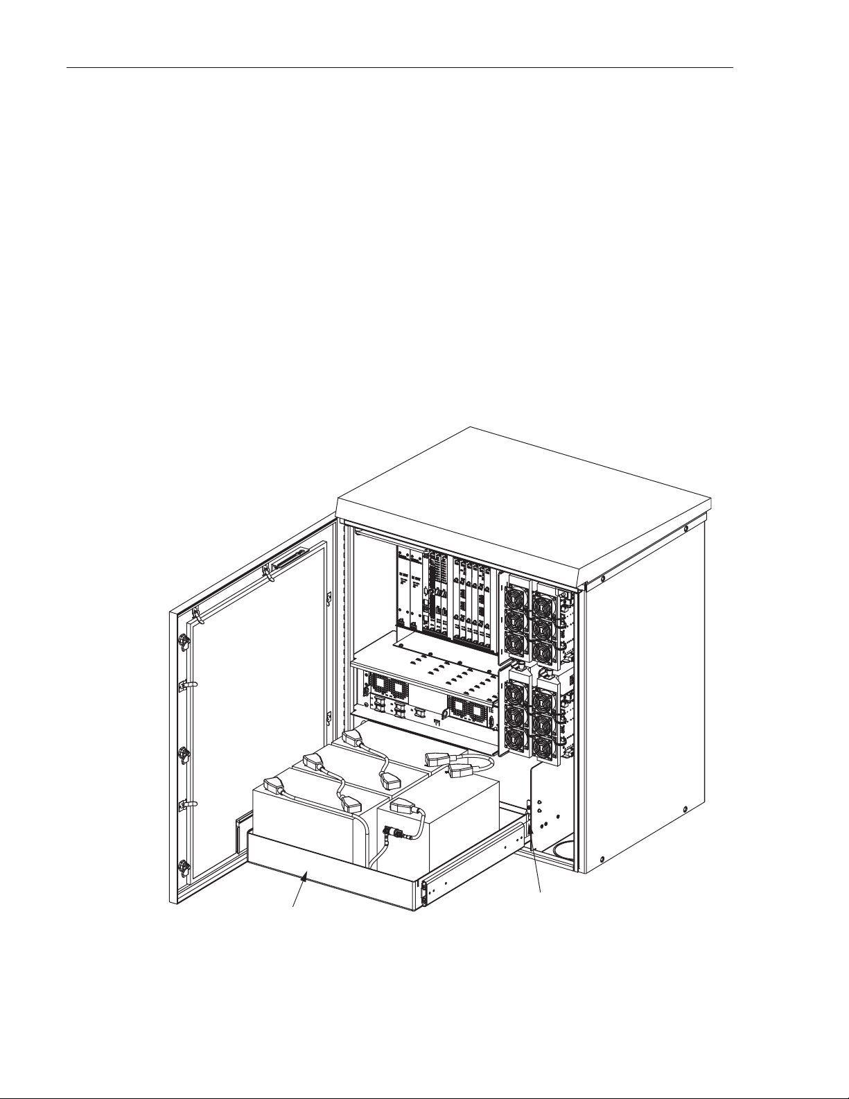
1. Open the RAN door.
2. Turn off the battery disconnect switch (labeled DISC) on the low voltage disconnect unit
in the RAN chassis. For location, refer to Figure 19 on Page 24. The LVD LED will light
up (red) when the batteries are disconnected.
3. Move the gravity latch in the battery drawer to the up position. Refer to Figure 34.
© 2006, ADC Telecommunications, Inc.
Page 51
Page 4
ADCP-75-210 • Issue 1 • November 2006
4. Pull out the battery drawer.
5. Move the gravity latch to the down position. Lock the telescopic slide into the locked out
position.
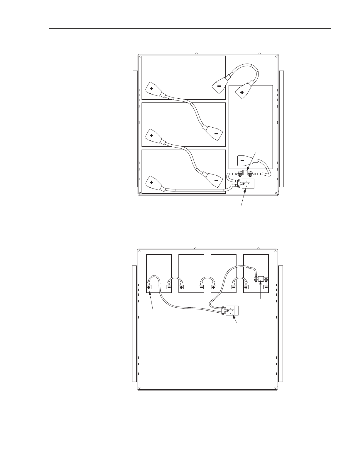
6. Install the batteries in the drawer as follows, referring to Figure 35 for extended batteries
and Figure 36 for extended batteries:
a. Place the batteries in the drawer in the configuration shown.
b. Wire the batteries in series as shown.
c. Find the wiring harness coiled up on the floor of the battery back up drawer and plug
the Anderson connectors together as shown.
7. Move the gravity latch up, push the battery drawer in, and move the gravity latch down.
8. Reconnect the battery disconnect switch (DISC) on the LVD unit. For location, refer to
Figure 19 on Page 24. The LVD LED on the low voltage disconnect unit should will turn
off when the batteries are reconnected.
Page 52
© 2006, ADC Telecommunications, Inc.
BATTERY
DRAWER
21277-A
GRAVITY
LATCH
Figure 34. Open Battery Drawer
Page 5
ADCP-75-210 • Issue 1 • November 2006
70 AMP
FUSE
21288-A
ANDERSON
CONNECTOR
Figure 35. Extended Batteries in Drawer
70 AMP
FUSE
NOTE:
CUSTOMER TO COVER
EXPOSED TERMINALS
WITH ELECTRICAL TAPE.
ANDERSON
CONNECTOR
Figure 36. Glitch Batteries in Drawer
21289-A
Page 53
© 2006, ADC Telecommunications, Inc.
Page 6

ADCP-75-210 • Issue 1 • November 2006
3 INSTALLING AN EXTENSION RAN (POLE MOUNT)
Two RANs can be installed at the same location to provide up to eight bands at that location
using a common antenna. Each RAN requires its own separate power and RF cables and fiber
optical cable. Figure 37 shows a typical dual RAN pole mount installation.
ANTENNA
ANTENNA
MOUNTING
BRACKET
GROUND WIRE
TO ANTENNA
PRIMARY
POWER
SECONDARY
POWER
FIBER
2 IN. SCHEDULE 40
CONDUIT FOR POWER IN
CARLTON PT. NO.
49011-010 OR
EQUIVALENT
27.5 IN.
(69.85 CM)
100 IN.
(254 CM)
6 FT. (1.8 M)
TYPICAL
38.6 FT.
(11.8 M)
TYPICAL
ANTENNA
1.5 IN. SCHEDULE 40
POLE RISER FOR
FIBER OPTIC LINES
CARLTON PT. NO.
59010N OR
EQUIVALENT
31.25 IN.
(79.4 CM)
RF CABLES
TO RA N
(5 REQUIRED)
PRIMARY POWER
SECONDARY POWER LINE
FIBER OPTIC LINE
FIBER SPLICE CAN
3 IN. SCHEDULE 40
CONDUIT FOR RF CABLES
CARLTON PT. NO.
49013-010 OR
EQUIVALENT
JUNCTION
BOX
#6 AWG COPPER
GROUND WIRE TO
METER BOX, RAN,
AND ANTENNA
COPPER
GROUND
ROD
SIDE
VIEW
Materials Required (Customer Supplied):
• Three galvanized steel bolts with tensile strength of 20,500 lbs. or greater, 3/4 inch
diameter, of a length appropriate to pole diameter
Page 54
© 2006, ADC Telecommunications, Inc.
10 FT. (3 M)
TYPICAL
7 FT. (2.1 M)
TYPICAL
FRONT
VIEW
21295-A
Figure 37. Typical Dual RAN Pole-Mount Installation
Page 7

ADCP-75-210 • Issue 1 • November 2006
• Three nuts, three flat washers, three 3 in. square curved washers, and three split ring
washers for bolts
Materials Required, ADC Supplied:
• RAN fixturing angle P/N 1001509P001 (X2)
• 1/4-20 X 3/4 hex bolts (X4)
• 2 in. through hull bulkhead fitting
• Flexible grommet
Use the following procedure to install an expansion RAN. Refer to Figure 38.
Note: This procedure assumes that the expansion RAN is installed on a utility pole
directly above the existing RAN.
1. Open the existing RAN door.
2. Remove the solar shield from the existing RAN. Refer to the solar shield installation
procedure in Section 2.7.1 on Page 43 and do the steps in a reverse order.
2 IN. (5.08 CM)
BULKHEAD FITTING
SUPPLIED WITH
EXTENSION RAN
1.50 IN.
(3.8 CM)
KENNARD
FLEXIBLE GROMMET
SUPPLIED WITH
EXTENSION RAN
Figure 38. Dual RAN Pole Mount
21296-A
© 2006, ADC Telecommunications, Inc.
Page 55
Page 8

ADCP-75-210 • Issue 1 • November 2006
3. If RF cables will be routed from the existing RAN M/MCPLR or P/MCPLR module to the
extension RAN, remove the hole seal plugs located on the top right of the existing RAN
and on the bottom right of the extension RAN.
Note: In this case, the multicoupler modules, the PAAs, and the GPS in the existing RAN
will be providing input into the extension RAN RDC module, the PAAs, and the STF
module (ANT input) for some or all of bands 5-8. The associated RF cables from the
multicouplers will be routed out of the top of the existing RAN and into the bottom of the
extension RAN.
4. Bolt the fixturing angle to each side the expansion RAN pole mount bracket bottom holes
using the two 1/4-20 X 3/4 hex bolts.
5. Raise the assembly above the existing RAN and align the bottom of the fixturing angle
with the top of the existing pole mount bracket.
6. Bolt the fixturing angle to each side of the existing RAN pole mount bracket top holes
using the two 1/4-20 X 3/4 hex bolts.
7. Install the extension RAN pole mount bracket, RAN cabinet, and rain shields following
the instructions in Section 2.5.3 on Page 36, Section 2.5.4 on Page 38, and Section 2.5.5
on Page 38, respectively.
8. Install a solar shield on the extension RAN following the instructions in Section 2.7.1 on
Page 43.
9. Install a grounding wire on the extension RAN following the instructions in Section 2.7.2
on Page 44.
10. Install the RF cables from the antenna to the extension RAN following the instructions in
Section 2.7.3 on Page 45.
11. Install the fiber optic cable from the Hub to the extension RAN following the instructions
in Section 2.7.4 on Page 47.
12. Install AC power in the extension RAN following the instructions in Section 2.7.5 on Page
49.
13. Install backup batteries in the extension RAN following the instructions in Section 2.7.6
on Page 50.
14. Close and secure both RANs.
Page 56
© 2006, ADC Telecommunications, Inc.
Page 9

4 NON-STANDARD INSTALLATION PROCEDURES
This section contains other installation procedures that are not typically done at a RAN
installation. These procedures cover field installation of electronic modules and other
components like the RAN chassis fans.
4.1 Installing an Electronic Module
If installing an electronic module in the field, refer to the appropriate procedure in this section.
There is a procedure for each type of electronic module. For a comprehensive description of the
electronic modules including function, controls, and indicators, refer to the appropriate topic in
Section 1.7 on Page 10.
Typically, the RAN chassis is shipped populated with the appropriate modules based on the preordered system configuration. Installation of electronic modules is only required when
installing a new electronic module or when changing the the system configuration.
Note: Not all options and features are supported in combination.
ADCP-75-210 • Issue 1 • November 2006
The electronic modules install into predetermined slots in the chassis identified by the labels on
the fan access panel above the chassis. For an illustration of the fan access panel labels and a
listing of the slots, refer to Section 1.7 on Page 10.
Warn ing: Electronic components can be damaged by static electrical discharge. To prevent
ESD damage, always wear an ESD wrist strap when handling electronic components.
The interconnection diagram shown in Figure 39 and Figure 40 on the next two pages
summarizes the interconnections between the RAN chassis electronic modules and other
electronic components of the RAN such as rectifiers and PAAs.
Note: The interconnection diagram shows a typical configuration. Other configurations
are possible that would be interconnected slightly differently.
© 2006, ADC Telecommunications, Inc.
Page 57
Page 10

ADCP-75-210 • Issue 1 • November 2006
Page 58
© 2006, ADC Telecommunications, Inc.
21372-A
Figure 39. RAN Interconnection Diagram Part 1
Page 11

ADCP-75-210 • Issue 1 • November 2006
Figure 40. RAN Interconnection Diagram Part 2
21373-A
Page 59
© 2006, ADC Telecommunications, Inc.
Page 12

ADCP-75-210 • Issue 1 • November 2006
4.1.1 Installing a Central Processing Unit (CPU) Module
The Central Processing Unit (CPU) module installs into Slot 5 of the RAN chassis. Only one
CPU may be installed in the RAN chassis.
Note: For a description of the CPU module including function, controls, and indicators,
refer to Section 1.7.2 on Page 13. For a RAN chassis interconnection diagram, refer to
Figure 39 on Page 58.
Use the following procedure to install the CPU module (Figure 41):
1. Open the RAN door.
2. Locate the designated slot for the CPU module. The CPU module installs into Slot 5,
which is identified with a red colored card guide.
3. Remove the CPU module from the anti-static packaging and orient the module for
installation as shown in the figure.
4. Slide the CPU module into the designated slot within the RAN chassis.
5. Lock the IEL handles on the top and bottom of the CPU module into the cPCI chassis.
6. Tighten the two Phillips head screws inside the handles.
7. Connect the short CAT5e jumper (cable 1001478P001) between the “ENET” port on the
CPU module the “10BT” port on the SIF module.
Note: If there are two SIF modules present, connect the cable to the first SIF module
(leftmost SIF module when viewed from the front of the chassis).
21250-AX
Page 60
© 2006, ADC Telecommunications, Inc.
Figure 41. Installing a CPU Module
Page 13

ADCP-75-210 • Issue 1 • November 2006
4.1.2 Installing a Systems Interface (STF2) Module
The System Interface module (STF2) is installed into Slot 6 of the RAN Chassis. Only one
STF2 module may be installed per RAN chassis.
Note: For a description of the STF2 module including function, controls, and indicators,
refer to Section 1.7.3 on Page 14. For a RAN chassis interconnection diagram, refer to
Figure 39 on Page 58.
Use the following procedure to install the STF2 module (Figure 42):
1. Open the RAN door.
2. Locate the designated slot for the STF2 module. The module installs into Slot 6.
3. Remove the STF2 module from the anti-static packaging and orient for installation.
4. Slide the STF2 module into the designated slot within the RAN chassis.
5. Lock the IEL handles on the top and bottom of the STF2 module into the cPCI chassis and
tighten the handle screws.
6. Using cable 1001474P001, connect the RAN door switch to the RJ-45 connector labeled
DA (Door Alarm) on the front of the STF2 module.
7. Using cable 1955000P084, connect the GPS antenna to the SMA connector labeled ANT
(Antenna) in the center of the module.
8. Using cable 1001476P001, connect the RECT port on the STF2 module to the unlabeled
9-pin port on the Low Voltage Disconnect (LVD) unit. For location of the LVD port, refer
to Section 1.8.2 on Page 24.
21252-AX
Figure 42. Installing an STF2 Module
© 2006, ADC Telecommunications, Inc.
Page 61
Page 14

ADCP-75-210 • Issue 1 • November 2006
4.1.3 Installing a Synchronous Interface (SIF) Module
The Synchronous Interface Module (SIF) is installed into Slot 7 or Slot 8 of the RAN chassis.
One SIF module is required for each two bands installed in the RAN. For the first two bands use
Slot 7. For the second two bands, use Slot 8.
Note: For a description of the SIF module, including function, controls, and indicators,
refer to Section 1.7.4 on Page 15. For a RAN chassis interconnection diagram, refer to
Figure 39 on Page 58.
Use the following procedure to install the SIF module (Figure 43):
1. Open the RAN door.
2. Locate the designated slot for the SIF module. The module installs into Slot 7 or Slot 8.
Refer to the introductory text above for more information.
3. Remove the SIF from the anti-static packaging and orient for installation.
4. Slide the SIF into the designated slot within the RAN chassis.
5. Lock the IEL handles on the top and bottom of the SIF module into the cPCI chassis and
tighten handle screws.
21252-AX
6. If this SIF module is being installed into Slot 7, connect the short CAT5e jumper (cable
1001478P001) between the “10BT” port on the SIF and the “ENET” port on the CPU
module. (For a slot 8 SIF, no cable is required.)
7. Carefully route the internal fibers to the front of the SIF module.
Page 62
© 2006, ADC Telecommunications, Inc.
Figure 43. Installing an SIF Module
Page 15

ADCP-75-210 • Issue 1 • November 2006
8. If the optical transceiver is mounted into the SIF module, then connect the fiber to the dual
LC connector. If optical transceiver is not mounted into the SIF module, follow the SFP
installation procedure in Section 4.1.4 on Page 63.
4.1.4 Installing a Small Form-Factor Optical Transceiver (SFP)
The SFP installs in the front center of the SIF module.
Note: For a description of the SFP, refer to Section 1.7.5 on Page 17. See also the
description of the SIF module faceplate in Section 1.7.4 on Page 15.
Use the following procedure to install an SFP:-
1. Locate the transceiver socket on the front of the SIF and remove the port cover from the
socket.
2. The color of the transceiver extractor handle corresponds to the optical specifications of
the SFP and CWDM designations. Select the optical transceiver that is to be used to
communicate with the target RAN.
Note: For CWDM systems, it is extremely important that the correct wavelength be
installed in each SIF. Consult the site fiber plan for details
3. Remove the transceiver from the anti-static packaging and orient for installation.
4. Insert the optical transceiver into the socket until it locks into place.
5. Connect fiber or replace the optical transceiver dust cap if it was removed for installation.
4.1.5 Installing a RAN Down Converter (RDC or RDC2) Module
The RAN Down Converter (RDC) module may be installed into any of four slots in the RAN
chassis, depending on the band for which the module will be used. One RDC module is required
for each band. The four slots are:
• Slot 10 (labeled RDC A1): used for first band
• Slot 12 (labeled RDC A3): used for second band
• Slot 13 (labeled RDC A4): used for third band
• Slot 15 (labeled RDC A6): used for fourth band
Note: For a description of the module including function, controls, and indicators, refer to
Section 1.7.6 on Page 17. For a RAN chassis interconnection diagram, refer to Figure 39
on Page 58.
Use the following procedure to install an RDC or RDC2 module (Figure 44):
1. Identify the slot designated RAN chassis slot for the RDC module. This will be Slot 10,
12, 13, or 15. For more information, refer to the introductory text above.
2. Remove the RDC module from the anti-static packaging and orient the module for
installation.
© 2006, ADC Telecommunications, Inc.
Page 63
 Loading...