

Page 1

ADCP-50-404 • Issue 2 • November 1998
DMPS-10CE Power Supply
User Manual
Content Page
Revision History.......................................................................1
Admonishments.......................................................................1
1.GENERAL............................................................................2
2.DETAILED DESCRIPTION.................................................................2
2.1DMPS-10CE Power Supply (Basic) ......................................................2
3.DMPS-10EXP/CE EXPANSION MODULE........................................................3
4.SPECIFICATIONS.......................................................................4
5.OUTPUT CABLE ASSIGNMENTS.............................................................5
6.INSTALLATION........................................................................5
6.1DMPS-10CE Power Supply Installation....................................................5
7.DMPS-10EXP/CE EXPANSION MODULE INSTALLATION.............................................6
8.POWER-UP OF THE DMPS-10CE POWER SUPPLY.................................................7
9.REPLACING THE LINE FUSE...............................................................7
10.CUSTOMER INFORMATION AND ASSISTANCE...................................................8
Revision History
Admonishments
Important safety admonishments are used throughout this manual to warn of possible hazards
to persons or equipment. An admonishment identifies a possible hazard and then explains
what may happen if the hazard is not avoided. The admonishments — in the form of Dangers,
Warnings, and Cautions — must be followed at all times. These warnings are flagged by use
of the triangular safety icon (seen below), and are listed in descending order of severity of
injury or damage and likelihood of occurrence.
Danger:
injury, death, or substantial property damage if the hazard is not avoided.
Warning:
personal injury, death, or substantial property damage if the hazard is not avoided.
Caution:
personal injury or property damage if the hazard is not avoided.
ISSUE DATE REASON FOR CHANGE
Issue 1 06/96 Original
Issue 2 11/98 Update Customer Information and Assistance section.
Danger is used to indicate the presence of a hazard which will cause severe personal
Warning is used to indicate the presence of a hazard that can cause severe
Caution is used to indicate the presence of a hazard that will or can cause minor
2-70000-0344 Page 1
© 1998, ADC Telecommunications, Inc.
Page 2
ADCP-50-404 • Issue 2 • November 1998
1. GENERAL
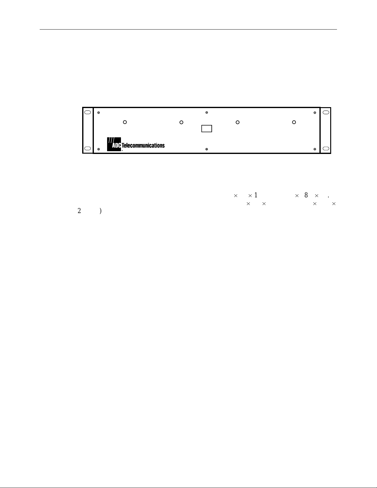
The DMPS-10CE Power Supply, as shown in Figure 1, is a rack mounted power supply
providing +5, +12, and –12 Volts dc. It is expandable (with the basic power supply and up to
three DMPS-10EXP/CE expansion modules) to a total of four dc power sources each
providing + 5, + 12 and –12 volts.
DMPS-10CE POWER SUPPLY
The power supply including the basic unit measures 3.5 19 11 inches (8.9 48.3 27.94
cm). Each DMPS-l0EXP/CE expansion module measures 3.5 3.9 9.22 inches (8.9 9.91
23.5 cm) and fits into the basic power supply.
The DMPS-10CE has EN 60950 classification for use in Europe.
2. DETAILED DESCRIPTION
2.1 DMPS-10CE Power Supply (Basic)
The DMPS-10CE power supply is designed for the ADC Telecommunications PatchSwitch
system but will work well with other applications. It will operate with any input voltage
between 190 and 240 volts ac and any frequency between 48 and 62 Hz. Manual adjustments
are not necessary. Only one ac input is necessary per shelf for up to four dc power sources (the
basic unit plus three expansion modules).
AC
DC OUT 1DC OUT 2DC OUT 3DC OUT 4
8257-A
Figure 1. DMPS-10CE Power Supply
Input ac power is supplied via a six-foot, three-conductor power cord equipped with a
standard three prong with ground plug on one end and a special IEC 3-pin connector on the
other. The special IEC 3-pin connector plugs into the back of the basic DMPS-l0CE power
supply. Fuses are installed at the factory as described in “Power-Up of the DMPS-l0CE Power
Supply” section, page 6 of this manual.
There are four LED indicator lights on the front of the unit to indicate whether the power
supply and expansion modules are operating. The right-most LED (marked “DC OUT 1”) is
for the basic unit. Each of the three others (marked DC OUT 2, 3 & 4) displays the condition
of the expansion modules.
Page 2
© 1998, ADC Telecommunications, Inc.
Page 3
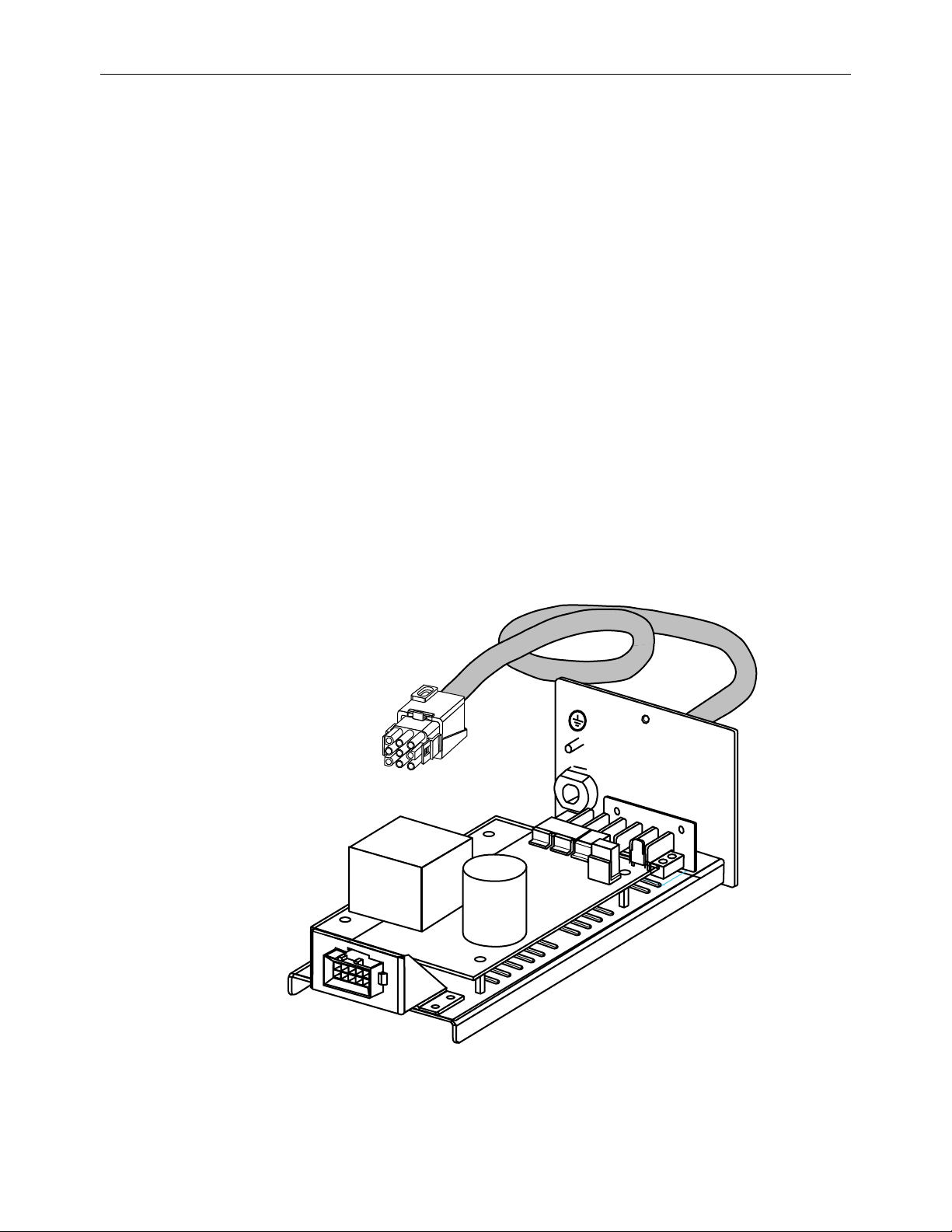
3. DMPS-10EXP/CE EXPANSION MODULE
The DMPS-l0EXP/CE Expansion Module, as shown in Figure 2, is designed to be installed
into the DMPS-10CE Basic Power Supply as dc power requirements expand at an installation.
The expansion module receives ac power from the basic shelf and is a completely selfcontained power supply in all other respects.
Up to three expansion modules can be mounted into the DMPS-l0CE Power Supply shelf. The
shelf requires a single ac power source (190 to 240 Vac, 48 to 62 Hz) to deliver up to 4 dc
outputs (via 9-pin cable connectors), each output supplying +5 Vdc, +12 Vdc and –12 Vdc.
Any input voltage between 190 and 240 volts ac can be accommodated without adjustment to
the power supply.
Outputs available from each of the modules (basic plus expansion modules) are +5 Vdc at up
to 4.5 Amps, +12 Vdc at up to 1.0 Amp, and –12 Vdc at up to 0.5 Amp.
Regulation is maintained on the respective voltages, keeping them constant to the tolerances
shown for the given current ranges:
+5 Vdc ± 5.0% for 0 to 4.5 Amps
ADCP-50-404 • Issue 2 • November 1998
+12 Vdc ± 10% for 0 to 1.0 Amps
–12 Vdc ± 10% for 0 to 0.5 Amps
J
2
J
3
J
4
E
1
J
1
Figure 2. DMPS-10EXP/CE Expansion Module
© 1998, ADC Telecommunications, Inc.
8258-A
Page 3
Page 4

ADCP-50-404 • Issue 2 • November 1998
Ripple voltage* is held to the following limits:
+5 Vdc, at or below 50 Millivolts, Peak-to-Peak
+12 Vdc, at or below 120 Millivolts, Peak-to-Peak
–12 Vdc, at or below 120 Millivolts, Peak-to-Peak
* Measured with a device having a 50 MHz bandwidth.
4. SPECIFICATIONS
PARAMETER SPECIFICATION
Input
Voltage 190/240 Vac
Current 2 Amps Maximum (4 Modules)
Frequency 48 to 62 Hz
Fusing (On rear of basic unit) 220 Vac: 4-Amp, Dual, Time Delay
Output Each Module
Voltage +5 Vdc ± 5%
Current 4.5 Amp DC Max. @ +5 V
Physical
Chassis 3.5 19 11 inches (8.9 48.3 27.94 cm)
Expansion Module 3.5 3.9 9.22 inches (8.9 9.91 23.5 cm)
Environmental
Operating Temperature 0 to 50 C (32 to 122 F)
Storage Temperature –40 to +70 C (–40 to 158 F)
Operating Humidity 10 to 80% non-condensing
Storage Humidity 5 to 90% non-condensing
Electromagnetic Compatibility Meets CISPR22 Class B radiated and conducted emissions.
+12 Vdc ± 10%
–12 Vdc ± 10%
1.0 Amp DC Max. @ +12 V
0.5 Amp DC Max. @ –12 V
Page 4
© 1998, ADC Telecommunications, Inc.
Page 5

5. OUTPUT CABLE ASSIGNMENTS
Output from the DMPS-l0CE Power Supply is delivered via a 6 foot, 16 gauge cable,
terminated in a 9-pin connector. Pin assignments on the connector are as follows:
Pin 1 — +5 Volts Pin 6 — Earth Ground
Pin 2 — +5 Volts Pin 7 — Common Ground for +5 and ± 12 V
Pin 3 — +12 Volts Pin 8 — Common Ground for +5 and ± 12 V
Pin 4 — No Connection Pin 9 — –12 Volts
Pin 5 — No Connection
See Figure 3 for sketch of the 9-pin connector.
ADCP-50-404 • Issue 2 • November 1998
6
3
28
9
6. INSTALLATION
6.1 DMPS-10CE Power Supply Installation
Remove each item from its shipping container and inspect the units for signs of damage. If
there are any damaged or missing parts, immediately file a claim with the commercial
common carrier or its agent, and notify ADC Telecommunications, Inc.
Normally, the ADC DMPS-10CE Power Supply is shipped with the standard single power
unit installed. Additional DMPS-10EXP/CE expansion modules are shipped in separate
containers. Occasionally, a power supply may be shipped with expansion modules installed. In
either case, installation of the power supply involves positioning the unit in the desired rack
space, near an ac utility outlet, and securing it with the mounting hardware normally used on
the mounting rack.
The DMPS-10CE Power Supply requires air for convection cooling. Air holes in
Note:
the top cover and bottom cover allow air to flow through the power supply chassis. For
this reason, be sure to mount the DMPS-10CE Power Supply in such a fashion as to
leave at least half of the top and bottom surfaces open to air movement.
1
7
4
4555-A
Figure 3. 9-Pin Connector
© 1998, ADC Telecommunications, Inc.
Page 5
Page 6

ADCP-50-404 • Issue 2 • November 1998
7. DMPS-10EXP/CE EXPANSION MODULE INSTALLATION
Remove the DMPS-10EXP/CE expansion module from its shipping container and inspect it
for signs of damage or missing parts. If there are any damaged or missing parts, immediately
file a claim with the common carrier or its agent, and notify ADC Telecommunications, Inc.
Notice the connector plug on the front of the expansion module and also notice the one extralong pin on the plug. This pin is for chassis ground, and is extra long to assure that the ground
connection is made first and broken last for your protection when installing or removing the unit.
Caution:
power is connected to the power supply shelf.
Proceed with the installation as follows:
(a)Set the ac switch at the front of the power supply to off (down position), and unplug the
(b)Remove and dispose of one of the four by four inch metal covers on the back of the
It is recommended that the expansion module not be installed or removed while
power cord of the supply from its ac utility outlet.
power supply by taking off the two screws holding it in place. Save the screws for use in
step (e) below.
(c)Notice the crimped sheet metal slots to the left hand side on the base of the power supply
shelf. The left-hand side of the “U” shaped base of the expansion module must slide into
these slots.
(d)Holding the expansion module with the “U” shaped base down and the 5-pin connector
plug forward, slide the module into the power supply, as shown in Figure 4, until the
connector pins engage the connector socket on the forward edge of the power supply.
Push in firmly to ensure proper connection of all pins in the plug.
CAUTION
ATTTENTION
CAUTION
MODEL
ATTENTION
VOLTS
HERTZ
DATE CODE
OUTPUT
AMPS
VOLTS
PH
UR
AMPS
CAT #
S/N
MADE
IN USA
DATE
CODE
CAUTION: DOUBLE POLE
NEUTRAL FUSING
250V 4A T
Page 6
© 1998, ADC Telecommunications, Inc.
8270-A
Figure 4. DMPS-10 EXP/CE Module Installation
Page 7

(e)Install the two screws removed in step (b) above to hold the expansion module in place.
(f)Connect the output power cable to the unit requiring the dc power. Pin assign-ments on
the cable connector are defined earlier in this manual.
It is recommended that the DMPS-10CE Power Supply or the DMPS-10EXP/CE
Note:
expansion modules be connected to a load before ac power is applied.
8. POWER-UP OF THE DMPS-10CE POWER SUPPLY
The DMPS-10CE Power Supply has dual panel-mount fuse holders (located on the rear) to
provide over current protection in each leg of the ac input source. As shipped, the power
supply is fused with two 4-amp, time-delay fuses. To power the DMPS-10CE power supply
proceed as follows:
(a)Turn the power switch located on the front panel to the OFF (“0”) position.
(b)Connect the 220 Vac power cord provided to the power supply shelf.
(c)Cut the plug off the other end of the power cord. Replace the plug with a plug that
matches your utility outlet.
ADCP-50-404 • Issue 2 • November 1998
(d)Connect the other end of the power cord to the utility outlet.
(e)Set the ac switch at the front of the DMPS-10CE Power Supply to the on (“I”) position.
(f)Verify that power LED is lit on the front of the power supply for the basic power supply
and any expansion modules installed.
9. REPLACING THE LINE FUSE
The line fuses are located in dual panel-mount fuse holders on the back of the unit. To replace
a line fuse/fuses:
(a)Set the ac switch to OFF (“0”) position.
(b)Remove the line cord from its utility outlet.
(c)Disconnect the line cord from the socket in back of the DMPS-10CE Power Supply.
(d)Turn fuse holder carrier in a counter-clockwise direction and remove fuse carrier from
fuse holder. Fuse location is shown in Figure 5.
(e)Use an Ohm meter to check fuses for opens.
(f)Replace the bad fuse/fuses and reinsert the fuse carrier back into its socket. Turn fuse
carrier clockwise until fully seated.
(g)Repeat Steps d – f for the other fuse.
(h)Reconnect the power cord to the Power Supply and its utility outlet.
(i)Set the ac switch to ON (“I”) position.
© 1998, ADC Telecommunications, Inc.
Page 7
Page 8

ADCP-50-404 • Issue 2 • November 1998
UTION
TENTION
CAUTION
ATTENTION
MODEL
VOLTS
HERTZ
DATE CODE
VOLTS
AMPS
AMPSOUTPUT
CAT #
S/N
PH
UR
MADE
IN USA
DATE
CODE
Figure 5. DMPS-10CE Fuse Location
10. CUSTOMER INFORMATION AND ASSISTANCE
For customers wanting information on ADC products or help in using them, ADC offers the
services listed below. To obtain any of these services by telephone, first dial the central ADC
telephone number, then dial the extension provided below.
The central number for calls originating in the U.S.A. or Canada is
originating outside the U.S.A. or Canada, dial country code “1” then dial
CAUTION: DOUBLE POLE
NEUTRAL FUSING
250V 4A T
FUSES
8271-A
1-800-366-3891
612-946-3000
. For calls
.
Sales Assistance
Extension 3000
• Quotation Proposals
• Ordering and Delivery
• General Product Information
Systems Integration
Extension 3000
• Complete Solutions (from Concept to Installation)
• Network Design and Integration Testing
• System Turn-Up and Testing
• Network Monitoring (Upstream or Downstream)
• Power Monitoring and Remote Surveillance
• Service/Maintenance Agreements
• Systems Operation
BBG Technical Assistance Center
Extension 3223
E-Mail: technical@adc.com
• Technical Information
• System/Network Configuration
• Product Specification and Application
• Training (Product-Specific)
• Installation and Operation Assistance
• Troubleshooting and Repair/Field Assistance
Product Return Department
Extension 3748
• ADC Return Authorization number and instructions
must be obtained before returning products.
E-Mail: repair&return@adc.com
Product information may also be obtained using the ADC web site at
www.adc.com
or by
writing ADC Telecommunications, Inc., P.O. Box 1101, Minneapolis, MN 55440-1101, U.S.A.
Page 8
© 1998, ADC Telecommunications, Inc.
Page 9

ADCP-50-404 • Issue 2 • November 1998
Contents herein are current as of the date of publication. ADC reserves the right to change the contents without prior notice.
no event shall ADC be l iable for a ny damage s resulting fr om loss of data , loss of use, or loss of pro fits and ADC further
disclaims any and all liability for indirect, incidental, special, consequential or other similar damages. This disclaimer of
liability applies to all products, publications and services during and after the warranty period.
This publication may be verified at any time by contacting ADC’s Technical Assistance Center at 1-800-366-3891, extension
3223 (in U.S.A. or Canada) or 612-946-3223 (outside U.S.A. and Canada), or by writing to ADC Telecommunications, Inc.,
Attn: Technical Assistance Center, Mail Station #77, P.O. Box 1101, Minneapolis, MN 55440-1101, U.S.A.
© 1998, ADC Telecommunications, Inc.
All Rights Reserved
Printed in U.S.A.
Page 9
In
 Loading...