

Page 1

FCC ID: F8I-DLCSMR2A User Manual - Part 5
11. Click on the HOST Config tab and on the REMOTE Config tab (see Figure 4-2). The
HOST Config display and the REMOTE Config display will open within the main
window.
12. Enter the Site Name and Site Number for both the HOST and the REMOTE unit. Refer to
Section 2.4 for details.
13. If the site has multiple host uni ts, reconnect the CAN cables to the HU’s NET IN and NET
OUT ports.
14. Verify that no Major (except Major Extern Alarm) or Minor alarms are being reported in
either the HOST or REMOTE Alarm displays and that all alarm fields (except Major
Extern Alarm) are green.
15. Click on the HOST RF tab (see Figure 4-2). The HOST RF display will open within the
main w i ndow.
16. Enter the Host Fwd Att (Forward Attenuation) values. This sets the forward input RF signal
level at the HU . Ref er to Section 2.5 for details. By default, this value is set to 0 dB. If the
DRIVE LED on the HU front panel was red, it should turn green when this step is completed.
ADCP-75-159 • Issue 1 • August 2003 • Section 4: Operation
17. Determine if the RF output power at the STM ANTENNA is at the correct level per
channel up to a composite maximum of +40.5 dBm. Refer to Section 2.6 for details.
18. Place the MUTE/NORM/RESET switch (on LPA front pa nel ) in the NORM position.
19. Verify that the STATUS indicator (on LPA front panel) tur ns from steady green to blinking
green.
20. Click on the REMOTE LPA tab (see Figure 4-2). The REMOTE PA display will open
within the main window.
21. Enter the Remote Fwd Att value. This adjusts the RF output signal level at the STM
ANTENNA port. Refer to S ection 2.7 for details. By default this value is set to 0 dB.
22. Click on the HOST RF tab (see Figure 4-2). The HOST RF display will open within the
main w i ndow.
23. Enter the Host Rev Att (Reverse Attenuation). This sets the reverse output RF signal
leve ls at the HU. Refer to Section 2.8 for details.
24. If a delay adjustment is required per the system design plan, enter the Host Fwd Dela y
and Host Rev Delay values. By default, the delay values are set to 0. Refer to Section 2.9
for details.
25. If a separate laptop computer loaded with the EMS software was used to initially
configure the system, disconnect the lapt op computer from the S ERVICE connector on the
HU front panel.
Note: For continuous monitoring of alarms, each HU and RU pair must remain
permanently connected to a PC-type desktop computer loaded with the EMS software.
When two or more systems are connected together through the CAN interface, only one
EMS computer is required to manage the networked HU and RU systems. The EMS
computer may be connected to the SERVICE port on any one of the HUs in the network.
26. Reco nnect the externa l alarm system or notify the alarm system provider tha t the turn-up
process has been completed.
© 2003, ADC Telecommunications, Inc.
Page 4-5
Page 2
ADCP-75-159 • Issue 1 • August 2003 • Section 4: Operation
2.2 Verify/Download HU and RU System Software
The HU’s and RU’s may require a system software download if they are not loaded with the
current system software. Use the following procedure to check the version number of the
system software and if necessary to download the current system software:
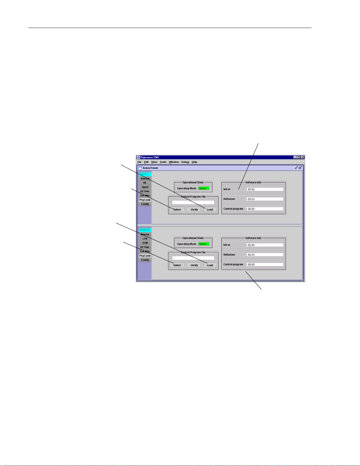
1. Click on the HOST Prg Load tab and on the R EMOTE Prg Load tab. The HOST Prg
Load display and the Remote Prg Load display will open within the EMS main window
as shown in Figure 4-3.
Click to start download to HOST.
Click to open Select Control
Program window for HOST
Verify software version
before starting download.
Click to start download to REMOTE.
Click to open Select
Control Program window for REMOTE.
Verify software version
before starting download.
Figure 4-3. HOST and REMOTE Prg Load Displays
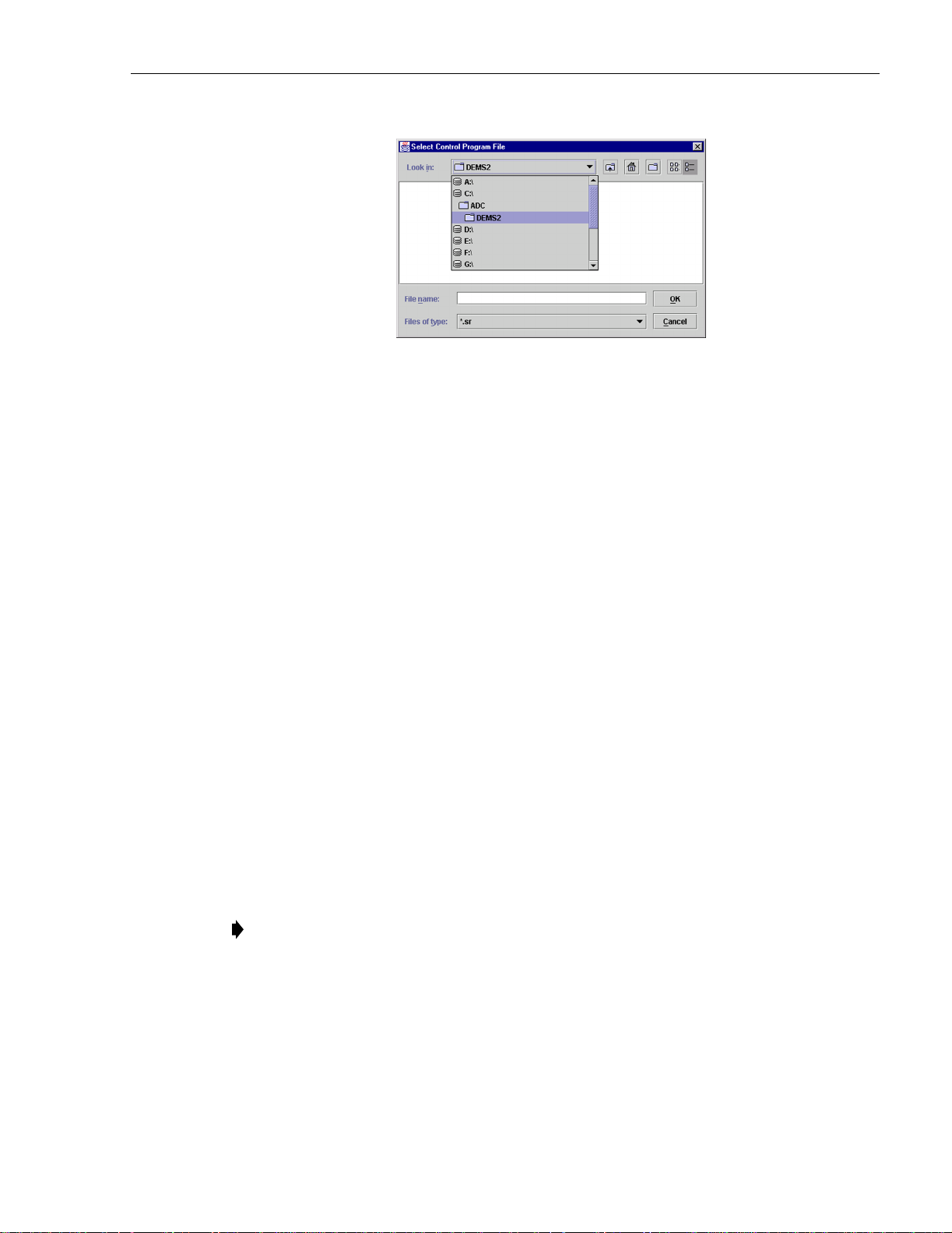
2. Click on the HOST Select button (see Figure 4-3). The Select Control Program File
window will open as shown in Figure 4-4. Browse until the folder where the Control
Program files are locate d is selected and the software files are displayed in the window.
3. Check the software version numbers shown in the Software Info section of the Prg Load
display against the version numbers of the software files displayed in the Select Cont rol
Program File window. If files in the Select Control Program File window are a later
version than those shown in the Prg Load display , proceed with the softw are download. If
the version numbers shown in the Software Info section are the same as the version
numbers of the files in the Select Control Program File window, the software download
is not required.
Page 4-6
© 2003, ADC Telecommunications, Inc.
Page 3
ADCP-75-159 • Issue 1 • August 2003 • Section 4: Operation
Figure 4-4. Select Control Program File Window
4. Select the first file to download and click on the OK button.
5. Click on the HOST Load b utton (see Figure 4-3) to st art th e dow nloa d .
6. Repeat steps 4 and 5 for each fil e that requires downloading.
7. Repeat steps 2 through 5 for the REMOTE.
2.3 Determine Forward Path Input Signal Level
The level of the composite RF input signal at the FORWARD RF IN port at the HU will vary
depending on the type of EBTS, the cable loss, the number of c hannels present, a nd the required
forward path c omposite power. If maximum composite RF output is required, the signal level of
the composite forward path RF signal at the HU forward path input must be adjusted to fall
within a range of –20 to –40 dBm. If the signal level is not within thi s r ange, it must be adjusted
to fall within this range through the use of an external attenuator capable of handling the EBTS
forward path output power.
If using the SMR Primary Interface Panel or Expansion Panel, refer to the Digivance LRCS
Interface Panels User Manual (ADCP-75-143) for the procedures for measuring and adjusting
the input RF signal level at the HU. If connecting a single HU to a single EBTS, use the
following pr ocedure to measure and adjust the input RF signal level at the HU:
1. Connect a spectrum analyzer or power meter to the forward path output port of the EBTS.
The required signal levels and test points are shown in Figure 4-5.
Note: Check the input rating of the test equipment and the output rating of the EBTS. To
avoid burning out the spectrum analyzer or power meter, it may be necessary to insert a
30 dB 100W (or similar) attenuator bet ween the EBTS and test equipment.
2. If using a spectrum analyzer, proceed to step 3. If using a power meter, measure the
composite signal po wer from the EBTS and then proceed to step 5.
3. Measu re the RF level of a single ca rrier, such as the con trol channe l, in dBm. Mak e sure
the resolution bandwidth of the spectrum analyzer is 30 kHz. Maximum power in any
channel should not exce ed 5W (+37 dB).
© 2003, ADC Telecommunications, Inc.
Page 4-7
Page 4

ADCP-75-159 • Issue 1 • August 2003 • Section 4: Operation
4. Calculate the total composite signal power from the EBTS using the following formula:
= Pc + 10Log N
P
tot
Where,
is the total composite powe r in dBm
P
tot
is the power per carrier i n dBm as meas u red in s tep 3, and
P
c
N is the total number of channels.
5. Determine the total cable loss that is imposed by the forward path coaxial cable that links
the EBTS to the HU and also any insertion loss impos ed by splitters or combiners.
6. Subtract the total cable loss and any insertion losses from the total composite power
calculated in step 4.
7. Subtract –30 (midpoint of the required range) from the value determined in step 6. The
difference (which should be positive) equals the value of the external attenuator that is
required to reduce the forward path signal level to fall within the required range. The
following formula outlines the required calculations for steps 6 and 7:
– (Cable and insertion loss) – (–30) = Value of external atte nuator required
P
tot
Note: If the input signal level is already within the required range of –20 to –40 dBm, then
no external atte nuator is required.
8. Select an attenuat or that is as close to the value calculate d in step 7 as possi ble. Selec t a
value that will adjust the signal level of the composite input signal to fall within the
specified range.
9. Install the external attenuator in the coaxial cable that is connected to the FORWARD RF
IN port at the HU.
Caution: The Host Unit can be damaged if it is overdriven by the EBTS. Always install an
external protective attenuator at the Host Unit FORWARD RF IN port if the forward path
composite input signal level is greater than –20 dBm.
10. Subtract the value of the external attenuator used in step 9 from the total composite signal
power (P
) and record the result. This value will be required when setting the attenuation
tot
of the HU’s internal forward attenua tor.
Page 4-8
© 2003, ADC Telecommunications, Inc.
Page 5

ADCP-75-159 • Issue 1 • August 2003 • Section 4: Operation
ENHANCED BASE
TRANSCEIVER STATION
ADJUSTMENTS TO OUTPUT
SIGNAL LEVEL AS SET BY HOST
REVERSE PATH ATTENUATOR
RECEIVERS
HOST UNIT
0 to 20 dB
ATTENUATOR
(HOST REV ATT)
RF, OPTICS,
AND CONTROL
OPTICAL LINK
REMOTE UNIT
TRANS-
MITTERS
EXTERNAL
ATTENUATOR
0 to 20 dB
ATTENUATOR
(HOST FWD ATT)
INPUT SIGNAL LEVEL
(-30 dBm TYPICAL
COMPOSITE FOR
FULL POWER)
ADJUSTMENTS TO INPUT
SIGNAL LEVEL AS SET BY HOST
FORWARD PATH ATTENUATOR
MAXIMUM OUTPUT SIGNAL
LEVEL AT STM ANTENNA PORT
Figure 4-5. Signal Levels, Test Points, and Adjustments
RF, OPTICS,
AND CONTROL
0 to 20 dB
ATTENUATOR
(REMOTE FWD ATT)
DUPLEXER
LPA
ADJUSTMENTS TO
OUTPUT SIGNAL LEVEL
AS SET BY THE REMOTE
FORWARD ATTENUATOR
PRIMARY
ANTENNA
17000-B
© 2003, ADC Telecommunications, Inc.
Page 4-9
Page 6

ADCP-75-159 • Issue 1 • August 2003 • Section 4: Operation
2.4 Enter Site Name and Site Number
All HU’s and RU’s are programmed with the same site name and site number. It is therefore
necessary to assign a unique site name and site number to the HU and RU before they can be
connected to the same CAN. Use the following procedure to assign a unique site name and
number to each HU and RU system:
1. Click on the HOST Config tab and on the REMOTE Config tab. The HOST Config
display and the REMOTE Config display will open within the EMS main window as
shown in Figure 4-6.
Right-Click on the
point shown to open
pop-up screen
HOST Site Number
HOST Site Name
REMOTE Site Number
(Entered automatically
when the HOST site
number is selected)
REMOTE Site Name
Figure 4-6. HOST and REMOTE Config Displays
2. Right-click on the HOST Site Name field (see Figure 4-6). T h e Site N a me pop-up screen
will open as shown in Figure 4-7. Enter a unique name for the HOST . The name may be up
to 32 characters long and must not contain any spaces. The name may include numbers,
punctuation, and upper or low er case letters and must always begin with a letter. Click on
OK to close the screen and make the changes take effect.
Page 4-10
© 2003, ADC Telecommunications, Inc.
Figure 4-7. HOST Site Name Pop-Up Screen
Page 7

3. Right-click on the HOST Site Number (see Figure 4-6). The Site Number pop-up screen
will open. Enter any number between 1 and 24 and then click on OK to close the screen
and make the changes take effect.
4. Check the REMOTE Site Number field (see Figure 4-6). The REMOTE Site Number
does not have to be entered. When the HOST Site Number is entered, the system will
automatically enter the same number for the REMOTE Site Number.
5. Right-click on the REMOTE Site Name field (see Figure 4-6). The Site Name pop-up
screen will open. Enter a unique name for the REMOTE. The name may be up to 32
characters long and must not contain any spaces. The name may include numbers,
punctuation, and upper or lower case letters and must always begin with a letter. Click on
OK to close the screen and make the changes take effect.
6. Open the Tools menu at the top of the main window and then select Refresh Catalog to
make the new Host and Remote sit e names appear in the View menu.
2.5 Enter Host Forward Attenuation
The HU internal forward path attenuator setting determines the maximum composite output
signal level at the STM antenna port. The appropriate attenuation value for any particular
system is based on the number of channels the system is transporting and the level of the
composite forward path signal input at the HU’s FORWARD RF IN port. The maximum output
power that can be provided by the system is 40.5 dBm (11 Watts). The total forward path gain
that is provided by the system (with host and remote forward attenuators set to 0 dB) is 80.5
dBm. Use the following procedure to set the forward path attenuation to provide the maximum
composite output signal level:
ADCP-75-159 • Issue 1 • August 2003 • Section 4: Operation
1. Click on the HOST RF tab. The HOST RF display will open within the EMS main
window as shown in Figure 4-8.
2. Right-click on the Host Fwd Att section of the display (see Figure 4-8). The Host Fwd
Att pop-up screen will open as shown in Figure 4-9.
3. Obtain the value of the total composite input signal level as determined in step 10 of
Section 2.3.
4. Determine the appropriate value to enter for the Host forward path attenuator by
subtracting the required system output level (per system design plan) from 80.5 (the total
system gain) and then adding the composite input signal level. The result (see sample
calculation) is the amount of atte nuation required.
Atten Required = 80.5 – (Required Syste m Output Power) + (Composite Input Po wer)
5. Enter the attenuation value and click OK to close the pop-up screen and to make the
changes take effect.
© 2003, ADC Telecommunications, Inc.
Page 4-11
 Loading...