

Page 1
FCC ID: F8I-DLC1902A
ADCP-75-158
Preliminary Issue A
June 2003
Digivance™ 1900 MHz 20 Watt System with
Version 2.00.01 EMS Software
Installation and Operation Manual
18641-B
1263478 Rev A
Page 2

ADCP-75-158
Preliminary Issue A
June 2003
Digivance™ 1900 MHz 20 Watt System with
Version 2.00.01 EMS Software
Installation and Operation Manual
1263478 Rev A
Page 3

ADCP-75-158 • Preliminary Issue A • June 2003 • Preface
COPYRIGHT
© 2003, ADC Telecommunications, Inc.
All Rights Reserved
Printed in the U.S.A.
REVISION HISTORY
ISSUE DATE REASON FOR CHANGE
A 06/2003 Original issue.
TRADEMARK INFORMATION
ADC and Pow erWorx are registered t rademarks of ADC Telecommunications, Inc.
Digivance is a trademark of ADC Telecommunications, Inc.
Procomm Plus is a r egistered trademar k of Quarterdeck Corporation.
DISCLAIMER OF LIABILITY
Contents herein are current as of the date of publication. ADC reserves the right to change the contents without prior notice. In no
event shall ADC be liable for any damages resulting from loss of data, loss of use, or loss of profits and ADC further
disclaims an y and all liability for indirec t, incidental, special, consequen tial or other similar dam ages. This discl aimer of
liability applies to all products, publications and services during and after the warranty period.
This publ ication may be verified at any time by contacting ADC ’s Technical Assistance Center at 1-800-366-3891, extension 73475
(in U.S.A. or Canada) or 952-917-3475 (outside U.S.A. and Can ada), or by e-mai l t o connectivity_tac@adc.com
Page ii
ADC Telecommunications, Inc.
P.O. Box 1101, Minneapolis, Minnesota 55440-1101
In U.S.A. and Canada: 1-800-366-3891
Outside U.S.A. and Canada: (952) 938-8080
Fax: (952) 917-1717
Page 4

TABLE OF CONTENTS
Content Page
ABOUT THIS MANUAL . . . . . . . . . . . . . . . . . . . . . . . . . . . . . . . . . . . . . . . . . . . . . . . . . . . . . . . . . . . . . . . . . . . . . . . . vii
RELATED PUBLICATIONS . . . . . . . . . . . . . . . . . . . . . . . . . . . . . . . . . . . . . . . . . . . . . . . . . . . . . . . . . . . . . . . . . . . . . . vii
ADMONISHMENTS . . . . . . . . . . . . . . . . . . . . . . . . . . . . . . . . . . . . . . . . . . . . . . . . . . . . . . . . . . . . . . . . . . . . . . . . . . viii
GENERAL SAFETY PRECAUTIONS . . . . . . . . . . . . . . . . . . . . . . . . . . . . . . . . . . . . . . . . . . . . . . . . . . . . . . . . . . . . . . . .viii
STANDARDS CERTIFICATION . . . . . . . . . . . . . . . . . . . . . . . . . . . . . . . . . . . . . . . . . . . . . . . . . . . . . . . . . . . . . . . . . . . . ix
LIST OF ACRONYMS AND ABBREVIATIONS . . . . . . . . . . . . . . . . . . . . . . . . . . . . . . . . . . . . . . . . . . . . . . . . . . . . . . . . . . . ix
1 INTRODUCTION. . . . . . . . . . . . . . . . . . . . . . . . . . . . . . . . . . . . . . . . . . . . . . . . . . . . . . . . . . . . . . . . . . . . . . . . 1-1
2 1900 MHZ 20 WATT SYSTEM OVERVIEW . . . . . . . . . . . . . . . . . . . . . . . . . . . . . . . . . . . . . . . . . . . . . . . . . . . . . .1-1
2.1 Basic System Components . . . . . . . . . . . . . . . . . . . . . . . . . . . . . . . . . . . . . . . . . . . . . . . . . . . . . . . . . .1-1
2.2 Base Transceiver Station to Host Unit Interface . . . . . . . . . . . . . . . . . . . . . . . . . . . . . . . . . . . . . . . . . . . .1-3
2.3 Handset Interface . . . . . . . . . . . . . . . . . . . . . . . . . . . . . . . . . . . . . . . . . . . . . . . . . . . . . . . . . . . . . . . . 1-4
2.4 Local Service Interface. . . . . . . . . . . . . . . . . . . . . . . . . . . . . . . . . . . . . . . . . . . . . . . . . . . . . . . . . . . . .1-4
2.5 Remote NOC Interface . . . . . . . . . . . . . . . . . . . . . . . . . . . . . . . . . . . . . . . . . . . . . . . . . . . . . . . . . . . . . 1-5
3 SYSTEM FUNCTIONS AND FEATURES . . . . . . . . . . . . . . . . . . . . . . . . . . . . . . . . . . . . . . . . . . . . . . . . . . . . . . . .1-6
3.1 Fiber Optic Transport . . . . . . . . . . . . . . . . . . . . . . . . . . . . . . . . . . . . . . . . . . . . . . . . . . . . . . . . . . . . . . 1-6
3.2 Control and Monitoring Software . . . . . . . . . . . . . . . . . . . . . . . . . . . . . . . . . . . . . . . . . . . . . . . . . . . . . .1-9
3.3 Fault Detection and Alarm Reporting . . . . . . . . . . . . . . . . . . . . . . . . . . . . . . . . . . . . . . . . . . . . . . . . . . . 1-9
3.4 Powering . . . . . . . . . . . . . . . . . . . . . . . . . . . . . . . . . . . . . . . . . . . . . . . . . . . . . . . . . . . . . . . . . . . . . .1-9
3.5 Equipment Mounting and Configuration . . . . . . . . . . . . . . . . . . . . . . . . . . . . . . . . . . . . . . . . . . . . . . . . .1-9
ADCP-75-158 • Preliminary Issue A • June 2003 • Preface
SECTION 1:
OVERVIEW
SECTION 2:
DESCRIPTION
1 INTRODUCTION. . . . . . . . . . . . . . . . . . . . . . . . . . . . . . . . . . . . . . . . . . . . . . . . . . . . . . . . . . . . . . . . . . . . . . . . 2-3
2 HOST UNIT . . . . . . . . . . . . . . . . . . . . . . . . . . . . . . . . . . . . . . . . . . . . . . . . . . . . . . . . . . . . . . . . . . . . . . . . . . . 2-3
2.1 Primary Components . . . . . . . . . . . . . . . . . . . . . . . . . . . . . . . . . . . . . . . . . . . . . . . . . . . . . . . . . . . . . .2-3
2.2 Mounting . . . . . . . . . . . . . . . . . . . . . . . . . . . . . . . . . . . . . . . . . . . . . . . . . . . . . . . . . . . . . . . . . . . . . .2-3
2.3 Fault Detection and Alarm Reporting . . . . . . . . . . . . . . . . . . . . . . . . . . . . . . . . . . . . . . . . . . . . . . . . . . . 2-4
2.4 RF Signal Connections . . . . . . . . . . . . . . . . . . . . . . . . . . . . . . . . . . . . . . . . . . . . . . . . . . . . . . . . . . . . .2-4
2.5 RF Signal Level Adjustments. . . . . . . . . . . . . . . . . . . . . . . . . . . . . . . . . . . . . . . . . . . . . . . . . . . . . . . . . 2-4
2.6 Propagation Delay . . . . . . . . . . . . . . . . . . . . . . . . . . . . . . . . . . . . . . . . . . . . . . . . . . . . . . . . . . . . . . . .2-5
2.7 Optical Connection . . . . . . . . . . . . . . . . . . . . . . . . . . . . . . . . . . . . . . . . . . . . . . . . . . . . . . . . . . . . . . .2-5
2.8 Controller Area Network Interface Connection . . . . . . . . . . . . . . . . . . . . . . . . . . . . . . . . . . . . . . . . . . . . .2-5
2.9 Service Interface Connection. . . . . . . . . . . . . . . . . . . . . . . . . . . . . . . . . . . . . . . . . . . . . . . . . . . . . . . . . 2-5
2.10 Powering . . . . . . . . . . . . . . . . . . . . . . . . . . . . . . . . . . . . . . . . . . . . . . . . . . . . . . . . . . . . . . . . . . . . . .2-5
2.11 Cooling . . . . . . . . . . . . . . . . . . . . . . . . . . . . . . . . . . . . . . . . . . . . . . . . . . . . . . . . . . . . . . . . . . . . . . .2-6
2.12 User Interface . . . . . . . . . . . . . . . . . . . . . . . . . . . . . . . . . . . . . . . . . . . . . . . . . . . . . . . . . . . . . . . . . . . 2-6
3 REMOTE UNIT OUTDOOR CABINET . . . . . . . . . . . . . . . . . . . . . . . . . . . . . . . . . . . . . . . . . . . . . . . . . . . . . . . . . .2-7
© 2003, ADC Telecommunications , Inc.
Page iii
Page 5

ADCP-75-158 • Preliminary Issue A • June 2003 • Preface
TABLE OF CONTENTS
Content Page
3.1 Primary Components . . . . . . . . . . . . . . . . . . . . . . . . . . . . . . . . . . . . . . . . . . . . . . . . . . . . . . . . . . . . . . 2-8
3.2 Mounting . . . . . . . . . . . . . . . . . . . . . . . . . . . . . . . . . . . . . . . . . . . . . . . . . . . . . . . . . . . . . . . . . . . . . . 2-9
3.3 STM and LPA Module Installation . . . . . . . . . . . . . . . . . . . . . . . . . . . . . . . . . . . . . . . . . . . . . . . . . . . . . 2-9
3.4 WDM and CWDM Installation . . . . . . . . . . . . . . . . . . . . . . . . . . . . . . . . . . . . . . . . . . . . . . . . . . . . . . . . 2-9
3.5 Fiber Optic Cable Entry . . . . . . . . . . . . . . . . . . . . . . . . . . . . . . . . . . . . . . . . . . . . . . . . . . . . . . . . . . . . 2-9
3.6 Antenna Cable Connection . . . . . . . . . . . . . . . . . . . . . . . . . . . . . . . . . . . . . . . . . . . . . . . . . . . . . . . . . 2-10
3.7 AC Power Wiring and Grounding . . . . . . . . . . . . . . . . . . . . . . . . . . . . . . . . . . . . . . . . . . . . . . . . . . . . . 2-10
3.8 Ventilation . . . . . . . . . . . . . . . . . . . . . . . . . . . . . . . . . . . . . . . . . . . . . . . . . . . . . . . . . . . . . . . . . . . . 2-10
3.9 User Interface. . . . . . . . . . . . . . . . . . . . . . . . . . . . . . . . . . . . . . . . . . . . . . . . . . . . . . . . . . . . . . . . . . 2-10
4 REMOTE UNIT INDOOR MOUNTING SHELF . . . . . . . . . . . . . . . . . . . . . . . . . . . . . . . . . . . . . . . . . . . . . . . . . . . . 2-12
4.1 Primary Components . . . . . . . . . . . . . . . . . . . . . . . . . . . . . . . . . . . . . . . . . . . . . . . . . . . . . . . . . . . . . 2-12
4.2 STM and LPA Module Installation . . . . . . . . . . . . . . . . . . . . . . . . . . . . . . . . . . . . . . . . . . . . . . . . . . . . 2-13
4.3 WDM and CWDM Installation . . . . . . . . . . . . . . . . . . . . . . . . . . . . . . . . . . . . . . . . . . . . . . . . . . . . . . . 2-13
4.4 Fiber Optic Cable Installation . . . . . . . . . . . . . . . . . . . . . . . . . . . . . . . . . . . . . . . . . . . . . . . . . . . . . . . 2-13
4.5 Antenna Cable Connections . . . . . . . . . . . . . . . . . . . . . . . . . . . . . . . . . . . . . . . . . . . . . . . . . . . . . . . . 2-14
4.6 AC Power Wiring and Grounding . . . . . . . . . . . . . . . . . . . . . . . . . . . . . . . . . . . . . . . . . . . . . . . . . . . . . 2-14
4.7 User Interface. . . . . . . . . . . . . . . . . . . . . . . . . . . . . . . . . . . . . . . . . . . . . . . . . . . . . . . . . . . . . . . . . . 2-14
5 SPECTRUM TRANSPORT MODULE . . . . . . . . . . . . . . . . . . . . . . . . . . . . . . . . . . . . . . . . . . . . . . . . . . . . . . . . . 2-15
5.1 Primary Components . . . . . . . . . . . . . . . . . . . . . . . . . . . . . . . . . . . . . . . . . . . . . . . . . . . . . . . . . . . . . 2-15
5.2 Mounting . . . . . . . . . . . . . . . . . . . . . . . . . . . . . . . . . . . . . . . . . . . . . . . . . . . . . . . . . . . . . . . . . . . . . 2-16
5.3 Fault Detection and Alarm Reporting . . . . . . . . . . . . . . . . . . . . . . . . . . . . . . . . . . . . . . . . . . . . . . . . . . 2-16
5.4 Antenna Cable Connection . . . . . . . . . . . . . . . . . . . . . . . . . . . . . . . . . . . . . . . . . . . . . . . . . . . . . . . . . 2-16
5.5 RF Signal Level Adjustment . . . . . . . . . . . . . . . . . . . . . . . . . . . . . . . . . . . . . . . . . . . . . . . . . . . . . . . . 2-17
5.6 Optical Connection . . . . . . . . . . . . . . . . . . . . . . . . . . . . . . . . . . . . . . . . . . . . . . . . . . . . . . . . . . . . . . 2-17
5.7 Service Interface Connection . . . . . . . . . . . . . . . . . . . . . . . . . . . . . . . . . . . . . . . . . . . . . . . . . . . . . . . 2-17
5.8 Powering . . . . . . . . . . . . . . . . . . . . . . . . . . . . . . . . . . . . . . . . . . . . . . . . . . . . . . . . . . . . . . . . . . . . . 2-17
5.9 Cooling . . . . . . . . . . . . . . . . . . . . . . . . . . . . . . . . . . . . . . . . . . . . . . . . . . . . . . . . . . . . . . . . . . . . . . 2-17
5.10 User Interface. . . . . . . . . . . . . . . . . . . . . . . . . . . . . . . . . . . . . . . . . . . . . . . . . . . . . . . . . . . . . . . . . . 2-17
6 LINEAR POWER AMPLIFIER . . . . . . . . . . . . . . . . . . . . . . . . . . . . . . . . . . . . . . . . . . . . . . . . . . . . . . . . . . . . . . 2-19
6.1 Primary Components . . . . . . . . . . . . . . . . . . . . . . . . . . . . . . . . . . . . . . . . . . . . . . . . . . . . . . . . . . . . . 2-19
6.2 Mounting . . . . . . . . . . . . . . . . . . . . . . . . . . . . . . . . . . . . . . . . . . . . . . . . . . . . . . . . . . . . . . . . . . . . . 2-20
6.3 Fault Detection and Alarm Reporting . . . . . . . . . . . . . . . . . . . . . . . . . . . . . . . . . . . . . . . . . . . . . . . . . . 2-20
6.4 Powering . . . . . . . . . . . . . . . . . . . . . . . . . . . . . . . . . . . . . . . . . . . . . . . . . . . . . . . . . . . . . . . . . . . . . 2-20
6.5 Cooling . . . . . . . . . . . . . . . . . . . . . . . . . . . . . . . . . . . . . . . . . . . . . . . . . . . . . . . . . . . . . . . . . . . . . . 2-21
6.6 User Interface. . . . . . . . . . . . . . . . . . . . . . . . . . . . . . . . . . . . . . . . . . . . . . . . . . . . . . . . . . . . . . . . . . 2-21
7 INTERFACE PANELS (ACCESSORY) . . . . . . . . . . . . . . . . . . . . . . . . . . . . . . . . . . . . . . . . . . . . . . . . . . . . . . . . . 2-22
8 WAVELENGTH DIVISION MULTIPLEXER SYSTEM (ACCESSORY) . . . . . . . . . . . . . . . . . . . . . . . . . . . . . . . . . . . . . 2-23
9 COARSE WAVELENGTH DIVISION MULTIPLEXER SYSTEM (ACCESSORY) . . . . . . . . . . . . . . . . . . . . . . . . . . . . . . . 2-24
10 DIGIVANCE ELEMENT MANAGEMENT SYSTEM . . . . . . . . . . . . . . . . . . . . . . . . . . . . . . . . . . . . . . . . . . . . . . . . . 2-25
10.1 Primary Components . . . . . . . . . . . . . . . . . . . . . . . . . . . . . . . . . . . . . . . . . . . . . . . . . . . . . . . . . . . . . 2-25
10.2 Service Interface Connection . . . . . . . . . . . . . . . . . . . . . . . . . . . . . . . . . . . . . . . . . . . . . . . . . . . . . . . 2-26
Page iv
© 2003, ADC Telecommunications , Inc.
Page 6

TABLE OF CONTENTS
Content Page
10.3 NOC Interface Connection . . . . . . . . . . . . . . . . . . . . . . . . . . . . . . . . . . . . . . . . . . . . . . . . . . . . . . . . . . 2-26
10.4 EMS Software User Interface. . . . . . . . . . . . . . . . . . . . . . . . . . . . . . . . . . . . . . . . . . . . . . . . . . . . . . . . 2-26
11 SPECIFICATIONS. . . . . . . . . . . . . . . . . . . . . . . . . . . . . . . . . . . . . . . . . . . . . . . . . . . . . . . . . . . . . . . . . . . . . . 2-27
1 BEFORE STARTING INSTALLATION . . . . . . . . . . . . . . . . . . . . . . . . . . . . . . . . . . . . . . . . . . . . . . . . . . . . . . . . . . 3-1
1.1 Tools and Materials . . . . . . . . . . . . . . . . . . . . . . . . . . . . . . . . . . . . . . . . . . . . . . . . . . . . . . . . . . . . . . .3-1
1.2 Unpacking and Inspection. . . . . . . . . . . . . . . . . . . . . . . . . . . . . . . . . . . . . . . . . . . . . . . . . . . . . . . . . . . 3-2
2 FIBER OPTIC CABLE ROUTING AND INSTALLATION GUIDELINES . . . . . . . . . . . . . . . . . . . . . . . . . . . . . . . . . . . . . .3-2
3 WDM MOUNTING PROCEDURE (OPTIONAL ACCESSORY) . . . . . . . . . . . . . . . . . . . . . . . . . . . . . . . . . . . . . . . . . . . 3-4
4 HU MOUNTING PROCEDURE . . . . . . . . . . . . . . . . . . . . . . . . . . . . . . . . . . . . . . . . . . . . . . . . . . . . . . . . . . . . . . .3-6
5 CHASSIS GROUND CONNECTION . . . . . . . . . . . . . . . . . . . . . . . . . . . . . . . . . . . . . . . . . . . . . . . . . . . . . . . . . . . . 3-8
6 COAXIAL CABLE CONNECTIONS. . . . . . . . . . . . . . . . . . . . . . . . . . . . . . . . . . . . . . . . . . . . . . . . . . . . . . . . . . . . .3-8
7 OPTICAL CONNECTIONS. . . . . . . . . . . . . . . . . . . . . . . . . . . . . . . . . . . . . . . . . . . . . . . . . . . . . . . . . . . . . . . . . 3-10
7.1 Optical Connections Without WDM or CWDM system . . . . . . . . . . . . . . . . . . . . . . . . . . . . . . . . . . . . . . . 3-10
7.2 Optical Connections With WDM System . . . . . . . . . . . . . . . . . . . . . . . . . . . . . . . . . . . . . . . . . . . . . . . . 3-11
8 CONTROLLER AREA NETWORK CONNECTIONS . . . . . . . . . . . . . . . . . . . . . . . . . . . . . . . . . . . . . . . . . . . . . . . . . 3-13
9 EMS COMPUTER CONNECTION . . . . . . . . . . . . . . . . . . . . . . . . . . . . . . . . . . . . . . . . . . . . . . . . . . . . . . . . . . . . 3-14
10 EXTERNAL ALARM SYSTEM CONNECTIONS . . . . . . . . . . . . . . . . . . . . . . . . . . . . . . . . . . . . . . . . . . . . . . . . . . . 3-15
11 DC POWER CONNECTIONS . . . . . . . . . . . . . . . . . . . . . . . . . . . . . . . . . . . . . . . . . . . . . . . . . . . . . . . . . . . . . . . 3-16
ADCP-75-158 • Preliminary Issue A • June 2003 • Preface
SECTION 3:
HOST UNIT INSTALLATION
SECTION 4:
OPERATION
1 BEFORE STARTING OPERATION . . . . . . . . . . . . . . . . . . . . . . . . . . . . . . . . . . . . . . . . . . . . . . . . . . . . . . . . . . . .4-1
1.1 Tools and Materials . . . . . . . . . . . . . . . . . . . . . . . . . . . . . . . . . . . . . . . . . . . . . . . . . . . . . . . . . . . . . . .4-1
1.2 Readiness Check . . . . . . . . . . . . . . . . . . . . . . . . . . . . . . . . . . . . . . . . . . . . . . . . . . . . . . . . . . . . . . . . . 4-2
2 TURN-UP SYSTEM AND VERIFY OPERATION . . . . . . . . . . . . . . . . . . . . . . . . . . . . . . . . . . . . . . . . . . . . . . . . . . . . 4-2
2.1 Turn-Up Procedure. . . . . . . . . . . . . . . . . . . . . . . . . . . . . . . . . . . . . . . . . . . . . . . . . . . . . . . . . . . . . . . . 4-3
2.2 Verify/Download HU and RU System Software . . . . . . . . . . . . . . . . . . . . . . . . . . . . . . . . . . . . . . . . . . . . . 4-6
2.3 Determine Forward Path Input Signal Level . . . . . . . . . . . . . . . . . . . . . . . . . . . . . . . . . . . . . . . . . . . . . . 4-7
2.4 Enter Site Name and Site Number . . . . . . . . . . . . . . . . . . . . . . . . . . . . . . . . . . . . . . . . . . . . . . . . . . . . 4-10
2.5 Enter Host Forward Attenuation . . . . . . . . . . . . . . . . . . . . . . . . . . . . . . . . . . . . . . . . . . . . . . . . . . . . . . 4-11
2.6 Determine Output Signal Level at STM Antenna Port . . . . . . . . . . . . . . . . . . . . . . . . . . . . . . . . . . . . . . . 4-12
2.7 Enter Remote Forward Attenuation . . . . . . . . . . . . . . . . . . . . . . . . . . . . . . . . . . . . . . . . . . . . . . . . . . . . 4-13
2.8 Enter Host Reverse Attenuation . . . . . . . . . . . . . . . . . . . . . . . . . . . . . . . . . . . . . . . . . . . . . . . . . . . . . . 4-15
2.9 Enter Host Forward and Reverse Delay . . . . . . . . . . . . . . . . . . . . . . . . . . . . . . . . . . . . . . . . . . . . . . . . . 4-17
© 2003, ADC Telecommunications , Inc.
Page v
Page 7

ADCP-75-158 • Preliminary Issue A • June 2003 • Preface
TABLE OF CONTENTS
Content Page
1 SYSTEM MAINTENANCE OVERVIEW . . . . . . . . . . . . . . . . . . . . . . . . . . . . . . . . . . . . . . . . . . . . . . . . . . . . . . . . . 5-1
1.1 Tools and Materials. . . . . . . . . . . . . . . . . . . . . . . . . . . . . . . . . . . . . . . . . . . . . . . . . . . . . . . . . . . . . . . 5-1
2 FAULT DETECTION AND ALARM REPORTING . . . . . . . . . . . . . . . . . . . . . . . . . . . . . . . . . . . . . . . . . . . . . . . . . . . 5-2
3 FAULT ISOLATION AND TROUBLESHOOTING . . . . . . . . . . . . . . . . . . . . . . . . . . . . . . . . . . . . . . . . . . . . . . . . . . . 5-5
3.1 Host Unit Troubleshooting . . . . . . . . . . . . . . . . . . . . . . . . . . . . . . . . . . . . . . . . . . . . . . . . . . . . . . . . . . 5-6
3.2 STM Troubleshooting. . . . . . . . . . . . . . . . . . . . . . . . . . . . . . . . . . . . . . . . . . . . . . . . . . . . . . . . . . . . . . 5-8
3.3 LPA Troubleshooting . . . . . . . . . . . . . . . . . . . . . . . . . . . . . . . . . . . . . . . . . . . . . . . . . . . . . . . . . . . . . 5-10
4 TEST PROCEDURES . . . . . . . . . . . . . . . . . . . . . . . . . . . . . . . . . . . . . . . . . . . . . . . . . . . . . . . . . . . . . . . . . . . 5-11
4.1 Optical Power Test . . . . . . . . . . . . . . . . . . . . . . . . . . . . . . . . . . . . . . . . . . . . . . . . . . . . . . . . . . . . . . 5-11
4.2 Optical Loopback Test . . . . . . . . . . . . . . . . . . . . . . . . . . . . . . . . . . . . . . . . . . . . . . . . . . . . . . . . . . . . 5-12
5 MAINTENANCE PROCEDURES. . . . . . . . . . . . . . . . . . . . . . . . . . . . . . . . . . . . . . . . . . . . . . . . . . . . . . . . . . . . . 5-14
5.1 Scheduled Maintenance. . . . . . . . . . . . . . . . . . . . . . . . . . . . . . . . . . . . . . . . . . . . . . . . . . . . . . . . . . . 5-14
5.2 Remote Unit Outdoor Cabinet Filter Cleaning Procedure. . . . . . . . . . . . . . . . . . . . . . . . . . . . . . . . . . . . . 5-14
5.3 Host Unit Fan Replacement Procedure . . . . . . . . . . . . . . . . . . . . . . . . . . . . . . . . . . . . . . . . . . . . . . . . . 5-15
5.4 Spectrum Transport Module Fan Replacement Procedure . . . . . . . . . . . . . . . . . . . . . . . . . . . . . . . . . . . . 5-17
5.5 Linear Power Amplifier Fan Replacement Procedure . . . . . . . . . . . . . . . . . . . . . . . . . . . . . . . . . . . . . . . 5-19
SECTION 5:
MAINTENANCE
SECTION 6:
GENERAL INFORMATION
1 WARRANTY/SOFTWARE . . . . . . . . . . . . . . . . . . . . . . . . . . . . . . . . . . . . . . . . . . . . . . . . . . . . . . . . . . . . . . . . . 6-1
2 SOFTWARE SERVICE AGREEMENT . . . . . . . . . . . . . . . . . . . . . . . . . . . . . . . . . . . . . . . . . . . . . . . . . . . . . . . . . . 6-1
3 REPAIR/EXCHANGE POLICY . . . . . . . . . . . . . . . . . . . . . . . . . . . . . . . . . . . . . . . . . . . . . . . . . . . . . . . . . . . . . . . 6-1
4 REPAIR CHARGES. . . . . . . . . . . . . . . . . . . . . . . . . . . . . . . . . . . . . . . . . . . . . . . . . . . . . . . . . . . . . . . . . . . . . . 6-2
5 REPLACEMENT/SPARE PRODUCTS . . . . . . . . . . . . . . . . . . . . . . . . . . . . . . . . . . . . . . . . . . . . . . . . . . . . . . . . . . 6-2
6 RETURNED MATERIAL. . . . . . . . . . . . . . . . . . . . . . . . . . . . . . . . . . . . . . . . . . . . . . . . . . . . . . . . . . . . . . . . . . . 6-2
7 CUSTOMER INFORMATION AND ASSISTANCE . . . . . . . . . . . . . . . . . . . . . . . . . . . . . . . . . . . . . . . . . . . . . . . . . . . 6-3
Page vi
© 2003, ADC Telecommunications , Inc.
Page 8

ABOUT THIS MANUAL
This installati on and operation manual provides the following information:
• An overview of the Digivance 1900 MHz 20 Watt System.
• A description of the basic system components including the Host Unit (HU), Spectrum
Transport Module (STM), Linear Power Amplifier (LPA), Remote Unit (RU) outdoor
cabinet, RU indoor mounting shelf, and Digivance Element Management System (EMS).
• Installation pr ocedures for the HU.
• Procedures for tuning -up the system and verifying that the system is functioning properly.
• Procedures for maintaining the system including troubleshooting problems and replacing
faulty components.
• Product warranty, repair, return, and replacement information.
The procedures for installing the remote unit and for installing and using the EMS software are
provided in other publications which are referenced in the Related Publications section and at
appropriate points within this manual.
ADCP-75-158 • Preliminary Issue A • June 2003 • Preface
RELATED PUBLICATIONS
Listed belo w are all the related manuals, their cont en t, a nd their publication numbers. Copies of
these publications can be ordered by contacting the Technical Assistance Center at
1-800-366-3891,extension 73475 (in U.S.A. or Canada) or 952-917-3475 (outside U.S.A. and
Canada).
Title/Description ADCP Number
Digivance 20 Watt Indoor Remote Unit Installation Instructions 75-149
Provides instructions for installing the STM, LPA, and accessories in the indoor
remote unit mounting shelf and for installing and connecting the fiber optic,
coaxial, and AC power cables.
Digivance 20 Watt Outdoor Remote Unit Installation Instructions 75-148
Provides instructions for installing the STM, LPA, and accessories in the
outdoor remote unit cabinet and for installing and connecting the fiber optic,
coaxial, and AC power cables.
Digivance 20 Watt Remote Unit Cabinet Mounting Instructions 75-147
Provides instructions for locating and mounting the remote unit cabinet.
Digivance Element Management System V e rsion 2.0 User Manual 75-125
Provides instr uctions for inst alling the Digiv a nce Element Management System
software and for using both the Graphical User Interface (GUI) and the
Network Operations Center (NOC) versions of the software.
© 2003, ADC Telecommunications , Inc.
Page vii
Page 9

ADCP-75-158 • Preliminary Issue A • June 2003 • Preface
Digivance RF Transport Solution 800 and 1900 MHz Interface
Panels User Manual 75-144
Describes the 800 and 1900 MHz Conditioning Panel and Duplexing Pa nel and
provides procedur es for configuration and installation.
Digivance System Coarse Wavelength Division Multiplexer User Manual 75-142
Describes the Coarse Wavelength Division Multiplexer and provides
procedures for configuration and installati on.
ADMONISHMENTS
Important safety admonishments are used thr oughout this manual to warn of possible hazards to
persons or equipment. An admonishment identifies a possible hazard and then explains what
may happen if the hazard is not avoided. The admonishments — in the form of Dangers,
Warnings, and Cautions — must be followed at all times. These warnings are flagged by use of
the triangular alert icon (seen below), and are listed in descending order of severity of injury or
damage and likelihood of occurrence.
Danger: Danger is used to indicate the presence of a hazard that will cause severe personal
injury, death, or substantial property damage if the hazard is not avoided.
Warning: Warning is used to indicate the presence of a hazard that can cause s evere personal
injury, death, or substantial property damage if the hazard is not avoided.
Caution: Caution is used to indicate the presence of a hazard that will or can cause minor
personal injury or property damage if the hazard is not avoided.
GENERAL SAFETY PRECAUTIONS
Danger: This equipment uses a Class 1 Laser according to FDA/CDRH rules. Laser radiation
can seriously damage the retina of the eye. Do not look into the ends of any optical fiber. Do not
look directly into the optical transceiver of any digital unit or exposure to laser radiation may
result. An optical power meter should be used to verify active fibers. A protective cap or hood
MUST be immediately placed ov er any radiating trans ceiv er or optical fiber connec tor to avoid
the potential of dangerous amounts of radiation exposure. This practice also prevents dirt
particles from entering the adapter or connector.
Danger: Do not look into the ends of any optical fiber. Exposure to laser radiation may result.
Do not assume laser power is turned-off or the fiber is disconnected at the other end.
Danger: Wet conditions increase the potential for receiving an electrical shock when installing
or using electrically-powered equipment. To prevent electrical shock, never install or use
electrical equipment in a wet location or during a lightning storm.
Page viii
© 2003, ADC Telecommunications , Inc.
Page 10

Warning: The HU is powered by 48 VDC power which is supplied over customer-provided
wiring. To prevent electrical shock when installing or modifying the HU power wiring,
disconnect the wiring at the power source before working with uninsulated wires or terminals.
Caution: Always allow sufficient fiber length to permit routing of patch cords and pigtails
without severe bends. Fiber optic patch cords or pigtails ma y be permane ntly damaged if be nt
or curved to a radius of less than 2 inches (50 mm).
STANDARDS CERTIFICATION
FCC: This equipment complies with the applicable sections of Title 47 CFR Part 24.
UL/CUL: This equipment complies with UL and CUL 50 Standard for Enclosures for
Electrical Equipment. This equipment provides the degree of protection specified by IP43 as
defined in IEC Publication 529.
FDA/CDRH: This equipment uses a Class 1 LASER according to FDA/CDRH Rules. This
product conforms to all appli cable standards of 21 CFR Part 1040.
ADCP-75-158 • Preliminary Issue A • June 2003 • Preface
IC: This equipment complies with the applicable secti ons of RSS-131. The term “IC:” before the
radio ce rtif i cat io n number onl y signi f ie s th at Indu stry Cana da Technical Spec if i catio ns we re met.
LIST OF ACRONYMS AND ABBREVIATIONS
The acronyms and abbreviations used in this manual are detaile d in the following list:
AC Alte rnat i ng Current
ASCII A me ri can St an dard Code for Inform at io n Interc h ang e
Att Attenuation
AWG American Wire Gauge
BER Bit Error Rate
BTS Base Tr ansceiver Station
C Centigrade
CAN Controller Area Network
CDRH Center for Devic es and Radiological Health
CD-ROM Compact Disk Read Only Memory
COM Common
Config Configuration
CUL Canadian Underwriters La boratories
CWDM Coarse Wavelength Division Multiplexer
DC Direct Curren t
DCE Data Communications Equipment
DTE Data Terminal Equipment
EIA Electronic Industries Association
© 2003, ADC Telecommunications , Inc.
Page ix
Page 11

ADCP-75-158 • Preliminary Issue A • June 2003 • Preface
EMS Element Management System
ESD Electrostatic Dischar ge
F Fahrenheit
FCC Federal Communications Commission
FDA Food and Drug Administration
FSO Free Space Opti cs
Fwd Forward
GUI Graphi ca l Us er Inte rface
HU Host Unit
IC Industry Canada
LED Light Emitting Diode
LPA Linear Power Amplifier
MHz Mega Hertz
MPE Maximum Permissible Exposure
MTBF Mean Time Between Failu re
NC Normally Clo sed
NEM Network Element Manager
NO Normally Open
NOC Network Operations Cente r
NPT National Pipe Tapered
OSP Outsid e Plan t
PA Power Amplifier
PC Personal Computer
PCS Personal Communications System
Prg Program
Pwr Power
Rev Reverse
RF Radio Frequency
RMA Return Material Authorization
RU Remote U n it
RX Receive or Receiver
STM Spectrum Transport Module
TX Transmit or Transmitter
UL Underwriters Laboratories
VAC Volts Alternating Current
VDC Volts Direct Cu rre nt
VSWR Voltage Standing Wave Ratio
WECO Western Electric Company
WDM Wave Divis i on Multiplexe r
Page x
© 2003, ADC Telecommunications , Inc.
Page 12

SECTION 1: OVERVIEW
1 INTRODUCTION. . . . . . . . . . . . . . . . . . . . . . . . . . . . . . . . . . . . . . . . . . . . . . . . . . . . . . . . . . . . . . . . . . . . . . . . 1-1
2 1900 MHZ 20 WATT SYSTEM OVERVIEW . . . . . . . . . . . . . . . . . . . . . . . . . . . . . . . . . . . . . . . . . . . . . . . . . . . . . .1-1
2.1 Basic System Components . . . . . . . . . . . . . . . . . . . . . . . . . . . . . . . . . . . . . . . . . . . . . . . . . . . . . . . . . .1-1
2.2 Base Transceiver Station to Host Unit Interface . . . . . . . . . . . . . . . . . . . . . . . . . . . . . . . . . . . . . . . . . . . .1-3
2.3 Handset Interface . . . . . . . . . . . . . . . . . . . . . . . . . . . . . . . . . . . . . . . . . . . . . . . . . . . . . . . . . . . . . . . . 1-4
2.4 Local Service Interface. . . . . . . . . . . . . . . . . . . . . . . . . . . . . . . . . . . . . . . . . . . . . . . . . . . . . . . . . . . . .1-4
2.5 Remote NOC Interface . . . . . . . . . . . . . . . . . . . . . . . . . . . . . . . . . . . . . . . . . . . . . . . . . . . . . . . . . . . . . 1-5
3 SYSTEM FUNCTIONS AND FEATURES . . . . . . . . . . . . . . . . . . . . . . . . . . . . . . . . . . . . . . . . . . . . . . . . . . . . . . . .1-6
3.1 Fiber Optic Transport . . . . . . . . . . . . . . . . . . . . . . . . . . . . . . . . . . . . . . . . . . . . . . . . . . . . . . . . . . . . . . 1-6
3.2 Control and Monitoring Software . . . . . . . . . . . . . . . . . . . . . . . . . . . . . . . . . . . . . . . . . . . . . . . . . . . . . .1-9
3.3 Fault Detection and Alarm Reporting . . . . . . . . . . . . . . . . . . . . . . . . . . . . . . . . . . . . . . . . . . . . . . . . . . . 1-9
3.4 Powering . . . . . . . . . . . . . . . . . . . . . . . . . . . . . . . . . . . . . . . . . . . . . . . . . . . . . . . . . . . . . . . . . . . . . .1-9
3.5 Equipment Mounting and Configuration . . . . . . . . . . . . . . . . . . . . . . . . . . . . . . . . . . . . . . . . . . . . . . . . .1-9
_________________________________________________________________________________________________________
ADCP-75-158 • Preliminary Issue A • June 2003 • Section 1: Overview
1 INTRODUCTION
This section provides basic description, application, and configuration information about the
Digivance 1900 MHz 20 Watt System. Throughout this publication, all items referenced as
“accessory items” are not furnished with the basic product and must be purchased separately.
2 1900 MHZ 20 WATT SYSTEM OVERVIEW
The Digivance 1900 MHz 20 Watt System is an RF signal transport system that provides longrange RF coverage in areas w he re it i s im p rac tic al to pl ac e a Base Transceiver Stat ion (B T S) at
the antenna site. High real estate costs and community restrictions on tower and equipment
locations often make it difficult to install the BTS at the same location as the antenna. The
Digivance system is designed to overcome equipment placement problems by allowing base
stations to be hubbed at a central location while placing remote antennas at optimum locations
with minimal real estate requirements. With the Digivance system, RF signals can be
transport ed to o n e or mo re remo te l o cati o ns to expan d coverag e int o areas not receiving ser vic e
or to extend coverage into difficult to reach areas such as canyons, tunnels, or underground
roadways.
2.1 Basic System Components
The basic components of a Digivance 20 Watt System and their functions are shown in
Figure 1-1. A 20 Watt system consists of the Host Unit (HU) and the Remote Unit (RU). Both
an indoor and an outdoor remote unit are available. Control and monitoring functions are
provided b y the Digivance Element Management Sys tem (EMS), a PC-based softwar e program.
In addition, various acc essory items are ava ilable separately including a passive Wavelength
Division Multiplexer (WDM) system, an active Coarse Wavelength Division Multiplexer
(CWDM) system, conditioning and duplexing panels (for interfacing the HU with the BTS),
© 2003, ADC Telecommunications , Inc.
Page 1-1
Page 13

ADCP-75-158 • Preliminary Issue A • June 2003 • Section 1: Overview
network cables (for connecting multiple HU’s together), and a EMS cable (for connecting the
EMS c o m p u ter to th e HU).
BASE STATION
ANTENNA
HOST UNIT
BASE
TRANSCEIVER
STATION
WDM
WDM
REMOTE
UNIT
DUPLEXING
PANEL
(IF REQUIRED)
CONDITIONING
PANEL
NETWORK
OPERATIONS
CENTER
(REMOTE
INTERFACE)
T1 OR
OTHER
MEDIUM
RS-232 ASCII
RF
RF
RF
CONTROLLER
NETWORK
HOST UNIT
CONTROLLER
HOST UNIT
AREA
AREA
NETWORK
CWDM
CWDM
CWDM
CWDM
REMOTE
UNIT
REMOTE
UNIT
DIGIVANCE ELEMENT
MANAGEMENT SYSTEM (EMS)
Page 1-2
© 2003, ADC Telecommunications , Inc.
RS-232
CD-ROM WITH EMS
SOFTWARE
RS-232
LAPTOP WITH EMS
(LOCAL INTERFACE)
Figure 1-1. 20 Watt System Overview Diagram
RS-232
18513-A
Page 14

2.2 Base Transceiver Station to Host Unit Interface
The HU interfaces with the BTS which provides the RF channel inputs and outputs for a
designated sector. The BTS/HU interface may require installation of the Digivance Interface
Panels which are accessory products for the Digivance system. The Interface Panels are used
when multiple BTS’s and multiple Host Units require connection or when RF attenuation is
needed between the BTS and Host Unit.
Two types of Interface Panels are available: the Conditioning Panel and the Duple xing Panel. The
Conditioning Panel provides attenuation of the forward path signal to the level required for input
to the Host Unit. The Conditioning Panel also provides forward and reverse path combining and
splitt ing (as nee ded ) t o e nab le m ult i-BT S to s in gle H o st U nit, mu lti- B TS to m ulti -Ho st U n it, o r
single BTS to multi-Host Unit configurations. A typical single BTS to multi-Host Unit
conf iguratio n is shown in Figure 1-2.
ADCP-75-158 • Preliminary Issue A • June 2003 • Section 1: Overview
HOST UNIT
RF
COAXIAL
CABLES
HOST UNIT
BASE
TRANSCEIVER
STATION
CONDITIONING
PANEL
RF
RF
COAXIAL
CABLES
RF
HOST UNIT
18514-A
Figure 1-2. BTS/HU Interface with Conditioning Panel
The Duplexing Panel is used in conjunction with the Conditioning Panel when the BTS
provides a duplexed forward and reverse path RF connection as shown in Figure 1-3. The
Duplexing Panel separates the duplexed forward and reverse path signals. This allows the BTS
to be connected to the Host Unit which has separate forward and reverse path RF ports.
© 2003, ADC Telecommunications , Inc.
Page 1-3
Page 15

ADCP-75-158 • Preliminary Issue A • June 2003 • Section 1: Overview
BASE
TRANSCEIVER
STATION
HOST UNIT
RF
2.3 Handset Interface
The RU interfaces with the handsets (cell phones) through an antenna. In the reverse path, the
RU rece ives R F sig nal s fro m e ach h and set. The RU digi tiz es t he RF sig nal s and then conver ts
them to digital optical signals for transport to the HU over the fiber optic link. In the forward
path, the RU receives digital opti cal signals from the HU. The RU converts the optical signals to
RF signals for transmission to the handsets. The RU is connected to an antenna (not provided)
which transmits and receives the handset RF signals.
RF
DUPLEXING
PANEL
COAXIAL
CABLES
RF
CONDITIONING
PANEL
RF
COAXIAL
CABLES
RF
HOST UNIT
HOST UNIT
18515-A
Figure 1-3. BTS/HU Interface With Conditioning Panel and Duplexing Panel
2.4 Local Service Interface
Local communications with an individual Digivance system is supported through a loc al service
interface capab ility as shown in Figure 4. The primary component of the local interf ace is a PCtype laptop comp uter loaded with the Digivance Element Management System (EMS) software.
The EMS provides the v arious control and monitoring functions required for local management
of each Digivance system. The EMS computer can be directly connected to either the HU or RU
through the computer’s RS-232 port. Operation is done through the EMS Graphical User
Interface (GU I) . Th e G UI co n sist s of a se ries of screens from whic h the u s er sel ec ts t he d es ired
option or function. An RS-232 service port is provided on both the HU and the RU for
connecting the EMS computer.
Page 1-4
© 2003, ADC Telecommunications , Inc.
Page 16

HOST UNIT
RS-232
ADCP-75-158 • Preliminary Issue A • June 2003 • Section 1: Overview
REMOTE
UNIT
RS-232
CD-ROM WITH DIGIVANCE
ELEMENT MANAGEMENT
SYSTEM (EMS) SOFTWARE
LAPTOP WITH EMS
(LOCAL INTERFACE)
2.5 Remote NOC Interface
Remote communications between a Network Operations Center (NOC) and a networked
grouping of multiple Digivance systems is supported by a remote NOC interface capability as
shown in Figure 1-5. The prim ary component of the remote NOC interface is a PC-t ype desktop
computer loaded with the Digivance Element Management System (EMS) software. EMS
provides the various control and monitoring functions required for remote management of
multiple Digi vance systems through a NOC.
A Controller Area Network (CAN) port is provided on each HU so that up to twenty-four HU’s
can be networked together in daisy-chain fashion and controlled though the same EMS
computer. The EMS computer connects to the networked HU’s through the computer’s RS-232
port #1. All HU’s can then be controlled through the same EMS computer.
The NOC is connected to the EMS computer through a T1 system or other medium. The EMS
computer ’s RS- 232 por t #2 inter faces with the T1 sy stem equ ipment. The T1 e quipmen t must
be capable of interfa cing with an RS-232 ASCII interface port.
LAPTOP WITH EMS
(LOCAL INTERFACE)
18524-A
Figure 1-4. Local Service Interface
At the NOC, control and monitoring of the networked Digivance systems are effected through a
Network Element Manager (NEM) interface which requires only a VT100 terminal/emulator
for operation. The NEM interface language consists of simple ASCII text strings. All
communications are input as either SET or GET commands which result in ASCII text string
responses from the specified system or systems. The EMS desktop computer may also be used
locally to manage the networked Digivance systems. Local operation is through the EMS
software GUI.
© 2003, ADC Telecommunications , Inc.
Page 1-5
Page 17

ADCP-75-158 • Preliminary Issue A • June 2003 • Section 1: Overview
CONTROLLER
AREA
NETWORK
OPERATIONS
CENTER
(REMOTE
INTERFACE)
T1 OR
OTHER
MEDIUM
NETWORK
CONTROLLER
AREA
NETWORK
HOST UNIT
REMOTE
UNIT
HOST UNIT
REMOTE
UNIT
HOST UNIT
REMOTE
UNIT
RS-232 ASCII
3 SYSTEM FUNCTIONS AND FEATURES
This section describes various system level functions and features of the Digiva nce System.
3.1 Fiber Optic Transport
In a typical Digi vance 20 Watt system with a single HU and R U, the HU is connected to the RU
over a pair of single-mode optical fibers. One fiber is used to transport the forward path optical
signal. The other fiber is used to transport the reverse path optical signal. Because the optical
signal is digital, the input and output RF signal levels at the HU or the RU are not dependent on
the level of the optical signal or the length of the optical fiber. A diagram of the fiber optic
transport system for a typical Digivance system is shown in Figure 1-6. The Digivance 20 Watt
system does not support re verse path diversity at this time.
RS-232
DESKTOP COMPUTER WITH EMS
(LOCAL AND REMOTE INTERFACE)
Figure 1-5. Remote NOC Interface
CD-ROM WITH DIGVANCE
ELEMENT MANAGEMENT
SYSTEM (EMS) SOFTWARE
18525-A
The maximum length of the optical fibers is dependent on the loss specifications of the optical
fiber and the losses imposed by the various connectors and splices. The system provides an
optical budget of 25 dB (typical) when used with 9/125 single-mode fiber.
Page 1-6
© 2003, ADC Telecommunications , Inc.
Page 18

ADCP-75-158 • Preliminary Issue A • June 2003 • Section 1: Overview
FIBER OPTIC
LINK
HOST UNIT
FORWARD PATH
REVERSE PATH
REMOTE
UNIT
18526-A
Figure 1-6. Standard Fiber Optic Transport
In some applications, it may be desirable or necessary to combine the forward path and reverse
path optical signals from a single HU/RU pair onto a single optical fiber. This can be
accomplished by using a passive bi-directional Wavelength Division Multiplexer (WDM)
system. The optical wavelengths used in the Digivance syste m are 1550 nm for the forward path
and 1310 nm for the reverse path. Because the Digivance system uses different optical
wave lengths for the forward and reverse paths, both signals c an be combined on a single optical
fiber. One WDM module is mounted with the HU and the other WDM module is mounted with
the RU as shown in Figure 1-7. The WDM system is available as an accessory item.
FIBER OPTIC
LINK
HOST UNIT
WDM
FORWARD AND
REVERSE PATH
WDM
REMOTE
UNIT
18527-A
Figure 1-7. Wavelength Division Multiplexer Application
In some applications, it may be desirable or necessary to combine the forward and reverse path
optical signals from multiple HU’s and RU’s onto a single optical fiber. This can be
accomplished by using an active Coarse Wavelength Division M ultiplexer ( CWDM) system. Up
to four Digivance systems may be configured to operate over a single optical fiber. A CWDM
module is mounted with each HU and RU as shown in Figure 1-8. The CWDM system converts
the optical signa l transmitted by each HU and RU to a new optical wavelength that is unique for
each unit. This allows the CWDM system to distinguish between the optical signals generated
by each HU and RU and therefore to distribute those signals to the appropriate destination. The
CWDM system is available separately as an accessory item.
© 2003, ADC Telecommunications , Inc.
Page 1-7
Page 19

ADCP-75-158 • Preliminary Issue A • June 2003 • Section 1: Overview
HOST UNIT 1
HOST UNIT 2
HOST UNIT 3
HOST UNIT 4
CWDM
A
CWDM
B
CWDM
C
CWDM
D
FIBER OPTIC
LINK
FORWARD AND
REVERSE PATH
CWDM
A
CWDM
B
CWDM
C
CWDM
D
REMOTE
UNIT 1
REMOTE
UNIT 2
REMOTE
UNIT 3
REMOTE
UNIT 4
18528-A
Figure 1-8. Coarse Wavelength Division Multiplexer Application
A Free Space Opti cs (FS O ) syst em (t hat m eet s the Digivance system data rate p erfo r ma nc e an d
BER requirements) may be used in applications where it is desirable or necessary to bridge an
open span and where it is impractical to lay a f iber optic cable. One FSO transceiver unit may be
mounted on the HU side of the open span and the other FSO transceiver unit may be mounted
on the RU side of the open span. A system diagram of an FSO application is shown in
Figure 1-9. FSO systems are available from various equipment manufacturers.
FREE SPACE OPTICS LINK
HOST UNIT
FORWARD PATH
REVERSE PATH
FSO
TX/RX
FSO
TX/RX
Figure 1-9. Free Space Optics Application
FORWARD PATH
REVERSE PATH
REMOTE
UNIT
18530-A
Page 1-8
© 2003, ADC Telecommunications , Inc.
Page 20

3.2 Control and Monitoring Software
The Digivance EMS software supports control and monitoring functions for both the local and
remote service inter faces. The EMS softwar e is stored on a CD-ROM which is included with the
EMS software package. Software installation consists of copying the software files from the
CD-ROM to a designate d directory on the hard-drive of the EMS computer.
The EMS software is used to provision and configure the Digivance system for operation. This
includes selecting a sitename, setting alarm thresholds, and setting forward and reverse path RF
gain adjustments. The EMS software is also used to get alarm messages (individual or
summary), data measurements, or to upgrade the HU/RU system software. All control and
monitor functions (except software upgrade which can only be done using the EMS software
GUI) can be effected using either the NOC/NEM interface or the EMS software GUI.
3.3 Fault Detection and Alarm Reporting
LED indicators are provided on the front panel of the HU and on the front panels of the RU
modules to indicate if the system is normal or if a fault is detected. In addition, normally open
and normally closed alarm contacts (for both major and minor alarms) are provided at the HU
for connection to a customer-provided external alarm system. All alarms can also be accessed
thro ugh the NOC /N EM interfa c e o r th e E M S software G U I .
ADCP-75-158 • Preliminary Issue A • June 2003 • Section 1: Overview
3.4 Powering
The HU is powered by ±24 or ±48 VDC and must be hard-wired to a local office battery power
source through a fuse panel. A screw-down terminal strip is provided on the rear side of the HU
for the power connections.
The RU is powered by 120 or 240 VAC (50 or 60 Hz) and must be connected to an AC power
source through a 20 Amp breaker box. A three-wire cable is provided for the AC power
connections. A 120 VAC outlet should be installed near the RU for powering test equipment or
power tools. In certain applications, it may be necessary to install a surge protector (not
provided) in the AC power feed to pre vent equipment damage from AC po we r spikes.
3.5 Equipment Mounting and Configuration
The HU is designed for mounting in a non-cond ensing indoor environment such as inside a
wiring closet or within an environmentally-controlled cabinet. The HU is intended for rackmount applications and may mounted in either a 19- or 23-inch WECO or EIA equipment rack,
usually within 20 feet of the BTS.
The outdoor RU is designed for mounting in an outdoor en vironment. The outdoor RU c onsists
of a Spectrum Transport Module (STM), a Linear Power Amplifier (LPA) module, and a selfcontained cabinet which houses the modular components and protects them from the elements.
The RU cabinet is weather-tight but contact with salt-air mist should be avoided as it may
degrade the MTBF of the product. The outdoor cabinet can be mounted from a flat-vertical
surface, from a utility pole (requires pole-mount kit), or mounted on a pedestal (requires
© 2003, ADC Telecommunications , Inc.
Page 1-9
Page 21

ADCP-75-158 • Preliminary Issue A • June 2003 • Section 1: Overview
pedestal kit). Slots are provided within the cabinet for the STM and LPA modules. Storage
spools are provided for storing short lengths of excess fiber slack. A mounting slot is also
provided for a WDM or CWDM remote module (accessory items). A lighting protector for the
antenna is inc luded with the outdoo r cabine t to pr ev ent e qui pment damage f rom li ghting str ik es.
The indoor RU is designed for mounting in a non-condensing indoor environment such as
inside a wiring closet or within an environmentally-controlled cabinet. The indoor RU is
intended for rack-mount applications and may be mounted in either a 19- or 23-inch WECO or
EIA equipment rack. The indoor RU consists of a Spectrum Transport Module (STM), a Linear
Power Amplifier (LPA) module, and a mounting shelf that supports the modular components.
The mounting shelf installs in the equipment rack. Slots are provided in the mounting shelf for
the STM and LPA modules. Slots are also provided for mounting the WDM or CWDM remote
module (accessory items).
Page 1-10
© 2003, ADC Telecommunications , Inc.
Page 22

SECTION 2: DESCRIPTION
Content Page
1 INTRODUCTION. . . . . . . . . . . . . . . . . . . . . . . . . . . . . . . . . . . . . . . . . . . . . . . . . . . . . . . . . . . . . . . . . . . . . . . . 2-3
2 HOST UNIT . . . . . . . . . . . . . . . . . . . . . . . . . . . . . . . . . . . . . . . . . . . . . . . . . . . . . . . . . . . . . . . . . . . . . . . . . . . 2-3
2.1 Primary Components . . . . . . . . . . . . . . . . . . . . . . . . . . . . . . . . . . . . . . . . . . . . . . . . . . . . . . . . . . . . . .2-3
2.2 Mounting . . . . . . . . . . . . . . . . . . . . . . . . . . . . . . . . . . . . . . . . . . . . . . . . . . . . . . . . . . . . . . . . . . . . . .2-3
2.3 Fault Detection and Alarm Reporting . . . . . . . . . . . . . . . . . . . . . . . . . . . . . . . . . . . . . . . . . . . . . . . . . . . 2-4
2.4 RF Signal Connections . . . . . . . . . . . . . . . . . . . . . . . . . . . . . . . . . . . . . . . . . . . . . . . . . . . . . . . . . . . . .2-4
2.5 RF Signal Level Adjustments. . . . . . . . . . . . . . . . . . . . . . . . . . . . . . . . . . . . . . . . . . . . . . . . . . . . . . . . . 2-4
2.6 Propagation Delay . . . . . . . . . . . . . . . . . . . . . . . . . . . . . . . . . . . . . . . . . . . . . . . . . . . . . . . . . . . . . . . .2-5
2.7 Optical Connection . . . . . . . . . . . . . . . . . . . . . . . . . . . . . . . . . . . . . . . . . . . . . . . . . . . . . . . . . . . . . . .2-5
2.8 Controller Area Network Interface Connection . . . . . . . . . . . . . . . . . . . . . . . . . . . . . . . . . . . . . . . . . . . . .2-5
2.9 Service Interface Connection. . . . . . . . . . . . . . . . . . . . . . . . . . . . . . . . . . . . . . . . . . . . . . . . . . . . . . . . . 2-5
2.10 Powering . . . . . . . . . . . . . . . . . . . . . . . . . . . . . . . . . . . . . . . . . . . . . . . . . . . . . . . . . . . . . . . . . . . . . .2-5
2.11 Cooling . . . . . . . . . . . . . . . . . . . . . . . . . . . . . . . . . . . . . . . . . . . . . . . . . . . . . . . . . . . . . . . . . . . . . . .2-6
2.12 User Interface . . . . . . . . . . . . . . . . . . . . . . . . . . . . . . . . . . . . . . . . . . . . . . . . . . . . . . . . . . . . . . . . . . . 2-6
3 REMOTE UNIT OUTDOOR CABINET . . . . . . . . . . . . . . . . . . . . . . . . . . . . . . . . . . . . . . . . . . . . . . . . . . . . . . . . . .2-7
3.1 Primary Components . . . . . . . . . . . . . . . . . . . . . . . . . . . . . . . . . . . . . . . . . . . . . . . . . . . . . . . . . . . . . .2-8
3.2 Mounting . . . . . . . . . . . . . . . . . . . . . . . . . . . . . . . . . . . . . . . . . . . . . . . . . . . . . . . . . . . . . . . . . . . . . .2-9
3.3 STM and LPA Module Installation . . . . . . . . . . . . . . . . . . . . . . . . . . . . . . . . . . . . . . . . . . . . . . . . . . . . .2-9
3.4 WDM and CWDM Installation . . . . . . . . . . . . . . . . . . . . . . . . . . . . . . . . . . . . . . . . . . . . . . . . . . . . . . . .2-9
3.5 Fiber Optic Cable Entry. . . . . . . . . . . . . . . . . . . . . . . . . . . . . . . . . . . . . . . . . . . . . . . . . . . . . . . . . . . . .2-9
3.6 Antenna Cable Connection . . . . . . . . . . . . . . . . . . . . . . . . . . . . . . . . . . . . . . . . . . . . . . . . . . . . . . . . . 2-10
3.7 AC Power Wiring and Grounding . . . . . . . . . . . . . . . . . . . . . . . . . . . . . . . . . . . . . . . . . . . . . . . . . . . . . 2-10
3.8 Ventilation . . . . . . . . . . . . . . . . . . . . . . . . . . . . . . . . . . . . . . . . . . . . . . . . . . . . . . . . . . . . . . . . . . . . 2-10
3.9 User Interface . . . . . . . . . . . . . . . . . . . . . . . . . . . . . . . . . . . . . . . . . . . . . . . . . . . . . . . . . . . . . . . . . . 2-10
4 REMOTE UNIT INDOOR MOUNTING SHELF . . . . . . . . . . . . . . . . . . . . . . . . . . . . . . . . . . . . . . . . . . . . . . . . . . . . 2-12
4.1 Primary Components . . . . . . . . . . . . . . . . . . . . . . . . . . . . . . . . . . . . . . . . . . . . . . . . . . . . . . . . . . . . . 2-12
4.2 STM and LPA Module Installation . . . . . . . . . . . . . . . . . . . . . . . . . . . . . . . . . . . . . . . . . . . . . . . . . . . . 2-13
4.3 WDM and CWDM Installation . . . . . . . . . . . . . . . . . . . . . . . . . . . . . . . . . . . . . . . . . . . . . . . . . . . . . . . 2-13
4.4 Fiber Optic Cable Installation . . . . . . . . . . . . . . . . . . . . . . . . . . . . . . . . . . . . . . . . . . . . . . . . . . . . . . . 2-13
4.5 Antenna Cable Connections. . . . . . . . . . . . . . . . . . . . . . . . . . . . . . . . . . . . . . . . . . . . . . . . . . . . . . . . . 2-14
4.6 AC Power Wiring and Grounding . . . . . . . . . . . . . . . . . . . . . . . . . . . . . . . . . . . . . . . . . . . . . . . . . . . . . 2-14
4.7 User Interface . . . . . . . . . . . . . . . . . . . . . . . . . . . . . . . . . . . . . . . . . . . . . . . . . . . . . . . . . . . . . . . . . . 2-14
5 SPECTRUM TRANSPORT MODULE . . . . . . . . . . . . . . . . . . . . . . . . . . . . . . . . . . . . . . . . . . . . . . . . . . . . . . . . . . 2-15
5.1 Primary Components . . . . . . . . . . . . . . . . . . . . . . . . . . . . . . . . . . . . . . . . . . . . . . . . . . . . . . . . . . . . . 2-15
5.2 Mounting . . . . . . . . . . . . . . . . . . . . . . . . . . . . . . . . . . . . . . . . . . . . . . . . . . . . . . . . . . . . . . . . . . . . . 2-16
5.3 Fault Detection and Alarm Reporting . . . . . . . . . . . . . . . . . . . . . . . . . . . . . . . . . . . . . . . . . . . . . . . . . . 2-16
5.4 Antenna Cable Connection . . . . . . . . . . . . . . . . . . . . . . . . . . . . . . . . . . . . . . . . . . . . . . . . . . . . . . . . . 2-16
5.5 RF Signal Level Adjustment . . . . . . . . . . . . . . . . . . . . . . . . . . . . . . . . . . . . . . . . . . . . . . . . . . . . . . . . 2-17
5.6 Optical Connection . . . . . . . . . . . . . . . . . . . . . . . . . . . . . . . . . . . . . . . . . . . . . . . . . . . . . . . . . . . . . . 2-17
5.7 Service Interface Connection. . . . . . . . . . . . . . . . . . . . . . . . . . . . . . . . . . . . . . . . . . . . . . . . . . . . . . . . 2-17
5.8 Powering . . . . . . . . . . . . . . . . . . . . . . . . . . . . . . . . . . . . . . . . . . . . . . . . . . . . . . . . . . . . . . . . . . . . . 2-17
5.9 Cooling . . . . . . . . . . . . . . . . . . . . . . . . . . . . . . . . . . . . . . . . . . . . . . . . . . . . . . . . . . . . . . . . . . . . . . 2-17
ADCP-75-158 • Preliminary Issue A • June 2003 • Section 2: Description
© 2003, ADC Telecommunications , Inc.
Page 2-1
Page 23

ADCP-75-158 • Preliminary Issue A • June 2003 • Section 2: Description
5.10 User Interface. . . . . . . . . . . . . . . . . . . . . . . . . . . . . . . . . . . . . . . . . . . . . . . . . . . . . . . . . . . . . . . . . . 2-17
6 LINEAR POWER AMPLIFIER . . . . . . . . . . . . . . . . . . . . . . . . . . . . . . . . . . . . . . . . . . . . . . . . . . . . . . . . . . . . . . 2-19
6.1 Primary Components . . . . . . . . . . . . . . . . . . . . . . . . . . . . . . . . . . . . . . . . . . . . . . . . . . . . . . . . . . . . . 2-19
6.2 Mounting . . . . . . . . . . . . . . . . . . . . . . . . . . . . . . . . . . . . . . . . . . . . . . . . . . . . . . . . . . . . . . . . . . . . . 2-20
6.3 Fault Detection and Alarm Reporting . . . . . . . . . . . . . . . . . . . . . . . . . . . . . . . . . . . . . . . . . . . . . . . . . . 2-20
6.4 Powering . . . . . . . . . . . . . . . . . . . . . . . . . . . . . . . . . . . . . . . . . . . . . . . . . . . . . . . . . . . . . . . . . . . . . 2-20
6.5 Cooling . . . . . . . . . . . . . . . . . . . . . . . . . . . . . . . . . . . . . . . . . . . . . . . . . . . . . . . . . . . . . . . . . . . . . . 2-21
6.6 User Interface. . . . . . . . . . . . . . . . . . . . . . . . . . . . . . . . . . . . . . . . . . . . . . . . . . . . . . . . . . . . . . . . . . 2-21
7 INTERFACE PANELS (ACCESSORY) . . . . . . . . . . . . . . . . . . . . . . . . . . . . . . . . . . . . . . . . . . . . . . . . . . . . . . . . . 2-22
8 WAVELENGTH DIVISION MULTIPLEXER SYSTEM (ACCESSORY) . . . . . . . . . . . . . . . . . . . . . . . . . . . . . . . . . . . . . 2-23
9 COARSE WAVELENGTH DIVISION MULTIPLEXER SYSTEM (ACCESSORY) . . . . . . . . . . . . . . . . . . . . . . . . . . . . . . . 2-24
10 DIGIVANCE ELEMENT MANAGEMENT SYSTEM . . . . . . . . . . . . . . . . . . . . . . . . . . . . . . . . . . . . . . . . . . . . . . . . . 2-25
10.1 Primary Components . . . . . . . . . . . . . . . . . . . . . . . . . . . . . . . . . . . . . . . . . . . . . . . . . . . . . . . . . . . . . 2-25
10.2 Service Interface Connection . . . . . . . . . . . . . . . . . . . . . . . . . . . . . . . . . . . . . . . . . . . . . . . . . . . . . . . 2-26
10.3 NOC Interface Connection . . . . . . . . . . . . . . . . . . . . . . . . . . . . . . . . . . . . . . . . . . . . . . . . . . . . . . . . . 2-26
10.4 EMS Software User Interface . . . . . . . . . . . . . . . . . . . . . . . . . . . . . . . . . . . . . . . . . . . . . . . . . . . . . . . 2-26
11 SPECIFICATIONS . . . . . . . . . . . . . . . . . . . . . . . . . . . . . . . . . . . . . . . . . . . . . . . . . . . . . . . . . . . . . . . . . . . . . 2-27
_________________________________________________________________________________________________________
Page 2-2
© 2003, ADC Telecommunications , Inc.
Page 24

1 INTRODUCTION
This section describes the basic components of the Digivance 1900 MHz 20 Watt system
including the Host Unit (HU), the Remote Unit (RU), a nd the Digivance Element Management
System (EMS). Also described are various accessory items including the InterFace Panels,
Wavelength Division Multiplexer (WDM) system, and Coarse Wavelength Division Multiplexer
(CWDM) system. The RU is an assembly that consis ts of a cabinet (for outdoor applications) or
mounting shelf (for indoor applications), a Spectrum Transport Module (STM), and a Linear
Power Amplifier (LPA) module. For clarity, the various components that comprise the RU are
described separately.
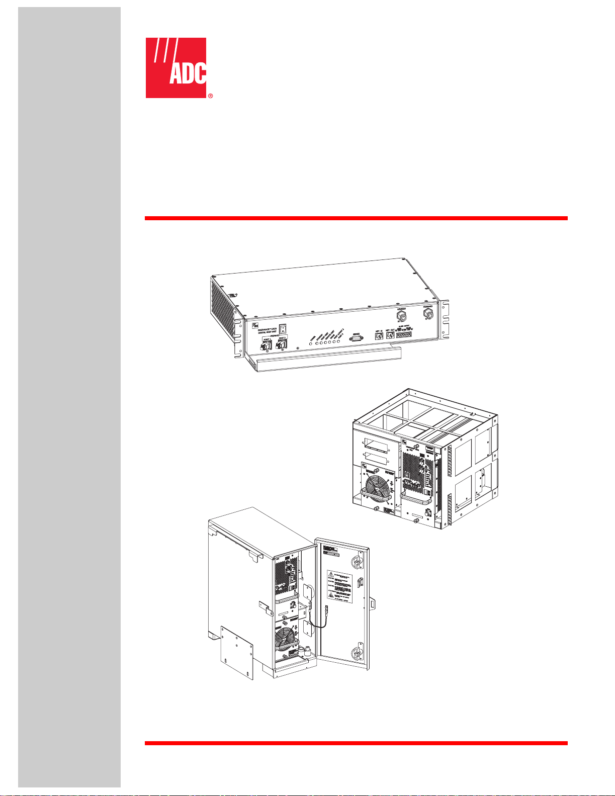
2 HOST UNIT
The HU, shown in Figure 2-1, serves as the BTS se rvicing uni t for the Digivance sy stem. Th e
HU provides the following basic functions:
• Provides a gain adjustable RF interface with the BTS.
• Provides a fiber optic interface with the RU.
ADCP-75-158 • Preliminary Issue A • June 2003 • Section 2: Description
• Digitizes the forward path composite RF signal.
• Converts the digitized forward path RF signal to a digital optical signal.
• Converts the digitized re verse path optical signal to a digitized RF signal.
• Converts the digitized re verse path RF signal to a composite RF signal.
• Signals alarm informat ion to an external alarm system through relay contact c losures
• Provides an RS-232 interface for connecting the EMS computer.
• Provides a CAN interface for networking multiple HUs.
2.1 Primary Components
The HU consists of an electronic circuit board assembly and a fan assembly that are mounted
within a powder-paint coated sheet metal enclosure. The enclosure provides a mounting point
for the circuit board and fan assemblies and controls RF emissions. The only user-replaceable
component is the fan assembly. The HU is designed for use within a non-condensing indoor
environment such as inside a wiring closet or cabinet. All controls, connectors, and indicators
(except the power terminal strip) are mounted on the HU front panel for convenient access.
Cable management functions for the coaxial cables and copper wiring are provided by a cable
management tray that ex tends outward from the HU front panel.
2.2 Mounting
The HU is intended for rack-mount applications. A pair of reversible mounting brackets is
provided that allow the HU to be mounted in either a 19-inch or 23-inch EIA or WECO
equipment rack. When installed, the front panel of the HU is flush with the front of the rack.
The cable management tray extends 3.9 inches (99 mm) beyond the front panel. Fasteners are
provided for secu ring the HU to the equipment rack.
© 2003, ADC Telecommunications , Inc.
Page 2-3
Page 25

ADCP-75-158 • Preliminary Issue A • June 2003 • Section 2: Description
3.5 INCHES
(89 mm)
15.3 INCHES
(389 mm)
11.4 INCHES
(290 mm)
2.3 Fault Detection and Alarm Reporting
The HU detects and reports various faults including host unit fault, optical fault, power fault,
temperature f ault, and RF fault. Various front panel Light Emitti ng Diode (LED) indicators turn
from green to red or yellow if a fault is detected. A set of alarm contacts (normally open and
normally closed) are provided for reporting an alarm to an external alarm system when a fault is
detected. Both major alarm (system operation seriously affected) and minor alarm (system
operation not affected or only slightly degrade d) contacts are provided.
17.2 INCHES
(437 mm)
Figure 2-1. Host Unit
FRONT PANEL
CABLE MANAGEMENT
TRAY
MOUNTING
BRACKET
(BOTH SIDES)
18531-A
The status of the HU, the alarm state (major or minor), and other alarm information is
summarized and reported over the service interface, the CAN interface, and also over the optical
interfa ce to the R U. In addit ion, the sta te of th e RU is received over the optical f iber and reported
over the service interface and the CAN interface. This detailed information may be accessed
remotely through the NOC/NEM interface or locally through the EMS software GUI.
2.4 RF Signal Connections
The RF signal connections between the HU and the BTS are supported through two N-type
female connectors. One connect or is used for the forward path RF signal. The other connector is
used for the reverse path RF signal. The current 20 Watt system does not support a diversity
reverse path. In most installations, it is usually necessary to install a Conditioning Panel and/or
Duplexing Panel (accessory items) to support the interface between the HU and the BTS. The
HU should be as close as possible to the BTS to minimize cable losses.
2.5 RF Signal Level Adjustments
The HU is equipped with several attenuators for adjusting the signal levels of the forward and
reverse path RF signals. The attenuators provide an attenuation adjustment range of 0 to 31 dB
and can be set in 1 dB increments. The attenuators are software controlled and are adjusted
thro ugh the NOC /N EM interfa c e o r th e E M S software G U I .
Page 2-4
© 2003, ADC Telecommunications , Inc.
Page 26

The host forward path attenuator adjusts the level of the input RF signal to the HU. Using the
forward path a ttenuator, an input signal with a nom inal composite signal level of –9 dBm to –40
dBm can be adjusted to produce maximum power output. Additional external attenuation is
required if the input signal level is greater than –9 dBm.
The host reverse pa th attenuator adjusts the level of the output RF signal and will add from
–1 dB of gain (attenuator set to 31 dB) to +30 dB of gain (attenuator set to 0 dB) to the RF
output signal at the HU.
2.6 Propagation Delay
The HU forward and reverse path propagation delays may be adjusted in 0.1 µsec increm ents
within a range of 0 to 63 µs. The propagation delay is software controlled and may be adjusted
thro ugh the NOC /N EM interfa c e o r th e E M S software G U I .
2.7 Optical Connection
Optical connections between the HU and the RU (STM) are supported through two SC-type
optical connector ports. One port is used for connecting the forward path optical signal and the
other port is used for connecting the primary reverse path optical signal.
ADCP-75-158 • Preliminary Issue A • June 2003 • Section 2: Description
2.8 Controller Area Network Interface Connection
Controller Area Network (CAN) interface connections between multiple HUs are supported by
a pair of RJ-45 jacks. One of the jacks is designated as the network IN port and the othe r jack is
designated as the network OUT port. The CAN interface allows up to 24 HUs to be connected
together (in daisy- chain fashion) and controlled through a single Digivance EMS computer.
2.9 Service Interface Connection
The service interface connection between the HU and the Digivance EMS computer is
supported by a single DB-9 female connector. The service connector provides an RS-232 DTE
interface. When multiple HUs are networked together, the supporting EMS computer may be
connected to the service con nector of any one of the networked HUs.
2.10 Powering
The HU is powered by ± 21 to ± 60 VDC power (nominal ± 24 or ± 48 VDC). The power is fed to
the HU through a screw-down type terminal strip located on the rear side of the unit. Power to
the HU must be supplied through a fuse panel such as the 20 position PowerWorx Fuse Panel
(accessory item). The power circuit for each HU must be protected with a 3 Amp GMT fuse. An
On/Off switch is pr ovided on the HU front panel.
© 2003, ADC Telecommunications , Inc.
Page 2-5
Page 27

ADCP-75-158 • Preliminary Issue A • June 2003 • Section 2: Description
2.11 Cooling
Continuous airflow for cooling is provided by dual fans mounted on the right side of the HU
housing. A minimum of 3 inches (76 mm) of clearance space must be provided on both the left
and right sides of the HU for air intake and exhaust. An alarm is provided if a high temperature
condition (>50º C/122º F) occurs. The fans may be field-replaced if either fan fails.
2.12 User Interface
The HU user interface consi sts of the v arious connectors, switches, termi nals, and LEDs that are
provided on the HU front and rear panels. The user interface points are indicated in Figure 2-2
and described in Table 2-1.
(1) DC POWER
ON/OFF SWITCH
(2)
PORT 1
NOTE: SHOWN WITHOUT
CABLE MANAGEMENT TRAY
(3)
PORT 2
(REFERENCE
ITEMS 4 - 9)
LED INDICATORS
Figure 2-2. Host Unit User Interface
Table 2-1. Host Unit User Interface
REF
NO
USER INTERFACE
DESIGNATION
DEVICE
1 I/0 On/Off rocker
switch
(10) SERVICE
INTERFACE
CONNECTOR
(14) REVERSE
RF OUT
CONNECTOR
(11) NET IN
(12) NET OUT
CONNECTOR
FUNCTIONAL
DESCRIPTION
Provides DC power on/off control.
(15) FORWARD
RF IN
(13) ALARM
OUTPUT
CONNECTOR
18532-A
2 PORT 1 SC connector
3 PORT 2 SC connector
4 POWE R Mult i- color ed L ED
5 STANDBY Multi-colored LED
6 HOST UNIT Multi-colored LED
Page 2-6
© 2003, ADC Telecommunications , Inc.
(single-mode)
(single-mode)
(green/yellow)
(green/yellow/red)
(green/yellow/red)
Output connection point for the forward path
optical fiber.
Input connection point for the reverse path primary optical fibe r.
Indicates if the HU is powered (green) or unpowered (off). See Note.
Indicate s if the system is in the Normal (off),
Standby (bli nking green), Test (blinking red), or
Program Load (blinking yel low) state. See Note.
Indicates if the HU is normal (green), ov erheated
(yellow), or fault y (red). See Note.
Page 28

ADCP-75-158 • Preliminary Issue A • June 2003 • Section 2: Description
Table 2-1. Host Unit User Interface, continued
REF
NO
7 REMOTE UNIT Multi-colore d LED
8 D R I V E Mult i- c o lored LED
9 PORT 1/PORT 2 Multi-colored LED
10 SERVICE DB-9 connector
11 NET IN RJ-45 jack (female) Connection point for CAN interface input cable.
12 NET OUT RJ-45 jack (female) Connection po int fo r CAN i nte rface o utpu t cable.
13 ALARM OUTPUT Screw-type terminal
14 REVERSE RF OUT N-type female RF
15 FORWARD RF IN N-type female RF
USER INTERFACE
DESIGNATION
DEVICE
(green/yellow/red)
(green/yellow/red)
(green/red)
(female)
connector (14–26
AWG)
coaxia l connector
coaxia l connector
Indica tes if no alar ms (green), a minor alarm
(yello w) , o r a majo r alar m ( re d) is r ep ort ed b y the
RU. See Note.
Indicate s if the level of the RF input signal to the
HU is normal (green), low (yellow), or high
(red). See Note.
Indicates if the reverse/forward pat h optical signals from the STM/HU are normal (green), if no
optical signals are detected (red), or if excessive
errors are detected (red). See Note.
Connection point for the RS-232 service interface cable.
Connection point for an external alarm system.
Includes normally open (NO), normally closed
(NC), and common (COM) wiring connections.
Output connection point for the primary reverse
path RF coaxial cable.
Input connection point for the forward path RF
coaxial cable.
FUNCTIONAL
DESCRIPTION
POWER 24–48 VDC
(Rear side - not shown)
Note: A more detailed des cription of LED operation is provided in Section 5.
3 REMOTE UNIT OUTDOOR CABINET
The R U cabinet, shown in Figure 2-3, is a NEMA-3R enclosure (with removable dust filters) that
provides the following basic functions:
• Houses the various electronic modules (STM and LPA) and accessories (WDM or
CWDM) and pro te cts th em fro m the w eath er.
• Provides elec trical interface connections for the STM and LPA modul es.
• Provides ve ntilation openings to allow f or entry of cool air and the escape of heated air .
• Provides a point for connecting the antenna cable and ground cable.
• Provides entry points for the fiber optic cable and AC power cable.
• Provides lightning protection
• Provides limited storage for fiber optic pigtails and patch cords.
• Provides elec trical connections for the CWDM
Screw-type terminal
strip
Connection point for the DC power wiring.
© 2003, ADC Telecommunications , Inc.
Page 2-7
Page 29

ADCP-75-158 • Preliminary Issue A • June 2003 • Section 2: Description
11.64 INCHES
(296 MM)
27.3 INCHES
(693 MM)
21.63 INCHES
(549 MM)
NOTE: EACH DIMENSION INCLUDES AN
ALLOWANCE FOR ANY COMPONENT THAT
PROJECTS OUTWARD FROM THE CABINET
SUCH AS THE DOOR LATCH.
3.1 Primary Components
The R U outdoo r cabine t consi st s of the e ncl osu re , mount ing sl ots for the ST M and LPA modules,
connectors and a wiring harness for interfacing the ST M and LPA modules, a mounting slot for
either the WDM or CWD M mo dule (acces sory items), lightning p ro tector, and two fiber storage
spools. The RU outdoor cabinet is designed for use in an outdoor environment. Opening the
hinged door provides full height and width access to the interior of the enclosure to facilitate
module and cable inst allation.
The enclosure is constructed of heavy gauge aluminum and is painted putty white for corrosion
protection. Connection and/or entry points are provided in the bottom of the enclosure for the
antenna coaxial cable, fiber optic cable, and AC power cable. Vent openings are provided in the
bottom of the enclosure to permit air exchange for cooling. The RU cabinet is weather-tight but
contact with salt-air mist should be avoided as it may degrade the Mean Time Between Failure
(MTBF) of the product. Drain holes in the bottom of the cabinet allow any moisture that does
enter the cabinet to drain out. The cabinet door is equipped with a sturdy latch so that the
enclosure may be padlocked to prevent unauthorized entry. A door open switch is provided so
that a major alarm is generated whenever the cabinet door is opened.
18564-B
Figure 2-3. Remote Unit Outdoor Cabinet
Page 2-8
© 2003, ADC Telecommunications , Inc.
Page 30

3.2 Mounting
The RU cabinet may be mounted on a flat vertical surface (such as the side of building) on a
utility pole, or on a pedestal. A special mounting bracket is provided with each enclosure.
Installation consists of securing the bracket to the mounting surface and then hanging the
enclosure from the bracket. The mounting bracket may be attached to a variety of surfaces such
as wood, concrete, or masonry. Various fasteners including hex-head capscrews, tee-nuts, and
concrete anchors are provided. A pole-mount kit (accessory item) is ava ilable for mounting the
cabinet from a utility pole. A pedestal-mounting kit (accessory item) is available for mounting
the cabinet on a flat horizonta l surface.
3.3 STM and LPA Module Installation
Two mounting slots are provided within the RU cabinet for installing the STM and LPA
modules. The mounting slots include tracks that guide each module into the installed position.
Separate mounting slots are provided for STM and LPA m odules. Two D-sub connectors (one
male, one fem ale) are lo cated at the rea r of each mo unting slo t. Each mou nting slot connector
mates with a corresponding D-sub connector located on the rear side of each module. A wiring
harness links the mounting slot connectors together. The connectors and the attached wiring
harness provi de the electrical int erface between th e STM and LPA modules. The mod ules are
held in the installed posi tion with captive screws.
ADCP-75-158 • Preliminary Issue A • June 2003 • Section 2: Description
3.4 WDM and CWDM Installation
A mounting slot is provided within the RU cabinet for installing a WDM or CWDM remote
module (accessory items). Each module is equipped with push-pull type fasteners for securing
the module to the mounting slot. A power cable is inclu ded with the cabinet for providi ng po wer
when a CWDM module is installed. Fiber storage spools are provided for storing excess pigtail
and/or patch cord slack.
3.5 Fiber Optic Cable Entry
A plastic cord connector is provided in the exterior bottom side of the RU cabinet for routing a
fiber optic cable into the enclosure. The cord connector provides cable strain relief and a
watertight seal at the fiber optic cable entry point. As the connector nut is tightened, a soft
neoprene bushing compresses to tightly grip the cable without applying excessive force to the
fibers. The cord co nnecto r can accommodate cable s that range from 0.375 to 0.875 inc hes (10 to
23 mm) in diameter. A spool is provided directly above the fiber optic cable entry hole for
storing exces s pigtail slack.
In a typical installation, the connectorized end of a mulit-fiber outside plant cable is routed into
the enclosure through the cord connector and the individual fibers are broken out into pigtails.
The pigta ils are connected t o t h e op t ical p orts o n t h e S T M a nd t he ex ce ss p ig ta il sl ack i s stored
on the fiber stora ge spool. The stub end of the cable is route d to an externa l spli ce enclosur e (not
provided) for splicing to the fiber optic cable.
© 2003, ADC Telecommunications , Inc.
Page 2-9
 Loading...