

Page 1
Preliminary
Preliminary Issue 3C
Digivance®Indoor Coverage Solution
800 MHz Single- or Multi-Mode Fiber
System Installation and Operation Manual
ADCP-75-130
August 2006
1371998 Rev 1
Page 2

Page 3

ADCP-75-130
Preliminary Issue 3C
August 2006
Digivance® Indoor Coverage Solution
800 MHz Single or Multi-Mode Fiber
System Installation and Operation Manual
1371998 Rev 1
Page 4

ADCP-75-130 • Issue 3C • August 2006 • Preface
COPYRIGHT
© 2006, ADC Telecommunications, Inc.
All Rights Reserved
REVISION HISTORY
ISSUE DATE REASON FOR CHANGE
Issue 1 03/2002 Original
Issue 2 09/2002 Updated to include new IC and UL certification statements, revised panel-type antenna designs, and
Issue 3 03/2004 Deleted all references to the LIU, inserted new references to the HPCP, added air quality specifications
Issue 3C 08/2006 Updated to include new specifications for the RF output signal level at the DRU.
new troubleshooting charts.
and warnings, and updated phone numbers and email addresses.
TRADEMARK INFORMATION
ADC, Digivance, and FiberGuide are registered trademarks of ADC Telecommunications, Inc.
LC is a trademark of Lucent Technologies Inc.
Telcordia is a registered trademark of Telcordia Technologies, Inc.
TORX is a registered trademark of Textron, Inc.
DISCLAIMER OF LIABILITY
Contents herein are current as of the date of publication. ADC reserves the right to change the contents without prior notice. In no
event shall ADC be liable for any damages resulting from loss of data, loss of use, or loss of profits and ADC further disclaims
any and all liability for indirect, incidental, special, consequential or other similar damages. This disclaimer of liability applies
to all products, publications and services during and after the warranty period.
This publication may be verified at any time by contacting ADC’s Technical Assistance Center at 1-800-366-3891, extension 73476
(in U.S.A. or Canada) or 1-952-917-3476 (outside U.S.A. and Canada), or by e-mail to wireless.tac@adc.com.
ADC Telecommunications, Inc.
P.O. Box 1101, Minneapolis, Minnesota 55440-1101
In U.S.A. and Canada: 1-800-366-3891
Outside U.S.A. and Canada: (952) 938-8080
Fax: (952) 917-1717
Page ii
Page 5

TABLE OF CONTENTS
Content Page
1 SYSTEM FUNCTIONAL OVERVIEW ..........................................................1
1.1 Basic System Components ......................................................... 1
1.2 Interface With BTS...............................................................1
1.3 Interface With Cellular Phones ...................................................... 1
1.4 Digital Fiber Optic Transport........................................................ 2
1.5 Capacity for Expansion and Extended Runs .............................................. 3
1.6 Power Requirements ............................................................. 3
1.7 Fault Detection and Alarm Reporting .................................................. 3
2 DIGITAL UNIT DESCRIPTION.............................................................. 3
2.1 Digital Host Unit Description........................................................ 3
2.2 Digital Remote Unit Description .....................................................7
2.3 Digital Expansion Unit Description................................................... 10
2.4 Terms and Definitions ........................................................... 13
2.5 Specifications................................................................. 13
3 INSTALLATION PLANNING AND SYSTEM DESIGN ............................................... 17
3.1 Base Station Interface Requirements ................................................. 17
3.2 Locating and Mounting Requirements ................................................ 19
3.3 Powering Requirements .......................................................... 20
3.4 Optical Options and Requirements................................................... 21
3.5 Coaxial Cable Requirements....................................................... 22
3.6 System Expansion Planning ....................................................... 23
3.7 DRU Antenna Options............................................................ 23
3.8 External Alarm System Reporting Requirements ......................................... 24
3.9 Maintenance Requirements ....................................................... 24
3.10 System Design Recommendations ................................................... 25
4 DIGITAL HOST UNIT INSTALLATION PROCEDURE ............................................... 28
4.1 System Plan Review and Pre-Installation Cable Routing .................................... 28
4.2 Tools and Materials............................................................. 28
4.3 Unpacking and Inspection......................................................... 29
4.4 Mounting Procecure ............................................................ 29
4.5 Chassis Ground Connections....................................................... 32
4.6 Coaxial Cable Connections ........................................................ 33
4.7 Modular Optical Transceiver Installation............................................... 34
4.8 Ports 1–6 Optical Connections......................................................
4.9 DC Power Connections ........................................................... 37
4.10 External Alarm System Connections .................................................. 38
4.11 AC Power Connections ........................................................... 39
4.12 Create As-Built Drawing .......................................................... 40
5 SYSTEM OPERATION.................................................................. 41
5.1 Tools and Materials............................................................. 41
5.2 Turn-Up System and Verify Operation ................................................. 41
ADCP-75-130 • Issue 3C • August 2006 • Preface
35
(continued)
© 2006, ADC Telecommunications, Inc.
Page iii
Page 6

ADCP-75-130 • Issue 3C • August 2006 • Preface
TABLE OF CONTENTS
Content Page
5.3 RF Input and Output Signal Level Adjustment ........................................... 44
5.4 Test System Performance ........................................................ 45
6 SYSTEM MAINTENANCE PROCEDURES ..................................................... 47
6.1 Tools and Materials ............................................................ 47
6.2 Fault Detection and Alarm Reporting................................................. 47
6.3 Fault Isolation and Troubleshooting ................................................. 48
6.4 Test Procedures ............................................................... 53
6.5 DHU or DEU Fan Replacement Procedure.............................................. 57
6.6 DHU or DEU Moudular Optical Transceiver Replacement Procedure ............................ 59
6.7 DRU Modular Optical Transceiver Replacement Proceudre.................................. 61
7 GENERAL INFORMATION............................................................... 64
7.1 Warranty/Software ............................................................. 64
7.2 Software Service Agreement ...................................................... 64
7.3 Repair/Exchange Policy.......................................................... 64
7.4 Repair Charges ............................................................... 65
7.5 Replacement/Spare Products ...................................................... 65
7.6 Returned Material ............................................................. 65
7.7 Customer Information and Assistance ................................................ 66
Page iv
© 2006, ADC Telecommunications, Inc.
Page 7

ABOUT THIS GUIDE
This installation and operation manual provides the following information:
• An overview of the Digivance Indoor Coverage Solution (ICS)
• A description of the basic system components including the Digital Host Unit (DHU),
Digital Expansion Unit (DEU), and the Digital Remote Unit (DRU).
• System requirements for planning the Digivance ICS installation.
• Procedures for installing the DHU.
• Procedures for operating and maintaining the Digivance ICS.
• Product warranty, repair, return, and replacement information
The procedures for installing the DEU and DRU are provided in other publications which are
referenced in the Related Publications section and at appropriate points within this manual.
RELATED PUBLICATIONS
ADCP-75-130 • Issue 3C • August 2006 • Preface
Listed below are related manuals and their publication numbers. Copies of these publications
can be ordered by contacting the ADC Technical Assistance Center at 1-800-366-3891,
extension 73476 (in U.S.A. or Canada) or 952-917-3476, (outside U.S.A. and Canada).
Title/Description ADCP Number
Digivance ICS Digital Expansion Unit Installation Instructions 75-111
Provides a description of the DEU and procedures for installation.
Digivance ICS Digital Remote Unit Installation Instructions 75-112
Provides a description of the DRU and procedures for installation.
Digivance ICS 800 and 1900 MHz High Power Conditioning
Panel User Manual 75-175
Provides a description of the 800 and 1900 MHz High Power Conditioning
Panel (HPCP) and procedures for installation.
Digivance ICS Single Band Remote Interface Unit
(800 and 1900 MHz Systems) User Manual 75-178
Provides a description of the RIU and procedures for installation.
© 2006, ADC Telecommunications, Inc.
Page v
Page 8

ADCP-75-130 • Issue 3C • August 2006 • Preface
ADMONISHMENTS
Important safety admonishments are used throughout this manual to warn of possible hazards
to persons or equipment. An admonishment identifies a possible hazard and then explains
what may happen if the hazard is not avoided. The admonishments — in the form of Dangers,
Warnings, and Cautions — must be followed at all times. These warnings are flagged by use
of the triangular alert icon (seen below), and are listed in descending order of severity of
injury or damage and likelihood of occurrence.
Danger: Danger is used to indicate the presence of a hazard that will cause severe personal
injury, death, or substantial property damage if the hazard is not avoided.
Warning: Warning is used to indicate the presence of a hazard that can cause severe
personal injury, death, or substantial property damage if the hazard is not avoided.
Caution: Caution is used to indicate the presence of a hazard that will or can cause minor
personal injury or property damage if the hazard is not avoided.
GENERAL SAFETY PRECAUTIONS
The following general admonishments apply throughout the procedures in this manual.
Warning: Wet conditions increase the potential for receiving an electrical shock when
installing or using electrically-powered equipment. To prevent electrical shock, never install
or use electrical equipment in a wet location or during a lightning storm.
Warning: Do not install the DRU in marine, industrial, or Intrinsic Safety (IS) environments
without an engineering review of the air quality including the presence of other constituent
gasses and dusts. Contact ADC for application assistance if necessary.
Warning: The DRU is powered by 48 VDC power which is supplied over customer-provided
wiring. To prevent electrical shock when installing or modifying the DRU power wiring,
disconnect the wiring at the power source before working with uninsulated wires or terminals.
Danger: This equipment uses a Class 1 Laser according to FDA/CDRH rules. Laser
radiation can seriously damage the retina of the eye. Do not look into the ends of any optical
fiber. Do not look directly into the optical adapters of any digital unit or exposure to laser
radiation may result. An optical power meter should be used to verify active fibers. A
protective cap or hood MUST be immediately placed over any radiating adapter or optical
fiber connector to avoid the potential of dangerous amounts of radiation exposure. This
practice also prevents dirt particles from entering the adapter or connector
Danger: Do not look into the ends of any optical fiber. Exposure to laser radiation may result. Do
not assume laser power is turned-off or the fiber is disconnected at the other end.
Danger: Always allow sufficient fiber length to permit routing without severe bends. Fibers may
be permanently damaged if bent/curved to a radius of less than 2 inches (50 mm).
Page vi
© 2006, ADC Telecommunications, Inc.
Page 9

STANDARDS CERTIFICATION
FCC: This equipment complies with the applicable sections of Title 47 CFR Part 22.
Caution: Modifications not expressly approved by the party responsible for compliance could
void the user’s authority to operate the equipment.
Part 15.5 General conditions of operation:
a. Persons operating intentional or unintentional radiators shall not be deemed to have any
vested or recognizable right to continue use of any given frequency by virtue of prior
registration or certificate of equipment.
b. Operation of an intentional, unintentional, or incidental radiator is subject to the
conditions that no harmful interference is caused and that interference must be accepted
that may be caused by the operation of an authorized radio station, by another intentional
or unintentional radiator, by industrial, scientific and medical (ISM) equipment, or by an
incidental operator.
c. The operator of a radio frequency device shall be required to cease operating the device
upon notification by a Commission representative that the device is causing harmful
interference. Operation shall not resume until the condition causing the harmful
interference has been corrected.
ADCP-75-130 • Issue 3C • August 2006 • Preface
UL/CUL: This equipment complies with UL and CUL 60950 Standard for Safety for
Information Technology Equipment, Including Electrical Business Equipment.
NEC/CEC: The DRU is suitable for use in environmental air space in accordance with
Section 300-22(c) of the National Electrical Code, and Sections 2-128, 12-010(3), and 12-100
of the Canadian Electrical Code, Part 1, C22.1.
FDA/CDRH: This equipment uses a Class 1 LASER according to FDA/CDRH Rules. This
product conforms to all applicable standards of 21 CFR Part 1040.
IC: This equipment complies with the applicable sections of RSS-131. The term “IC:” before
the radio certification number only signifies that Industry Canada Technical Specifications
were met.
LIST OF ACRONYMS AND ABBREVIATIONS
The acronyms and abbreviations used in this manual are detailed in the following list:
A Amperes
AC Alternating Current
AGC Automatic Gain Control
AMPS Advanced Mobile Phone Service
BTS Base Transceiver Station
CDMA Code Division Multiple Access
CDRH Center for Devices and Radiological Health
CEC Canadian Electrical Code
CUL Underwriters’ Laboratories of Canada
DAS Distributed Antenna System
© 2006, ADC Telecommunications, Inc.
Page vii
Page 10

ADCP-75-130 • Issue 3C • August 2006 • Preface
DC Direct Current
DEU Digital Expansion Unit
DHU Digital Host Unit
DRU Digital Remote Unit
EIA Electronic Industries Association
ERP Effective Radiated Power
ESD Electrostatic Discharge
FCC Federal Communications Commission
FDA Food and Drug Administration
HPCP High Power Conditioning Panel
ICS Indoor Coverage Solution
MM Multi-Mode
NEC National Electrical Code
NOC Network Operations Center
PWR Power
RIU Remote Interface Unit
RF Radio Frequency
RSSI Received Signal Strength Indication
RX Receive or Receiver
SM Single-Mode
TDMA Time Division Multiple Access
TX Transmit or Transmitter
UL Underwriters’ Laboratories
UPS Uninterruptible Power Supply
V Volts
VAC Volts Alternating Current
VDC Volts Direct Current
WECO Western Electric Company
Page viii
© 2006, ADC Telecommunications, Inc.
Page 11

1 SYSTEM FUNCTIONAL OVERVIEW
The Digivance ICS is a digitally distributed antenna system that provides in-building coverage
for cellular analog (AMPS) and digital (TDMA and CDMA) phone systems operating within
the 800 MHz frequency bands. Large buildings typically interfere with the transmission or
reception of cellular phone system signals by imposing high attenuation losses on RF signals.
The Digivance ICS is designed to overcome the attenuation losses that make cellular
communications within buildings or structures difficult or impossible. With the Digivance
ICS, cellular phone RF signals can be distributed to the interior areas of any building or
structure to eliminate dead spots and improve reception.
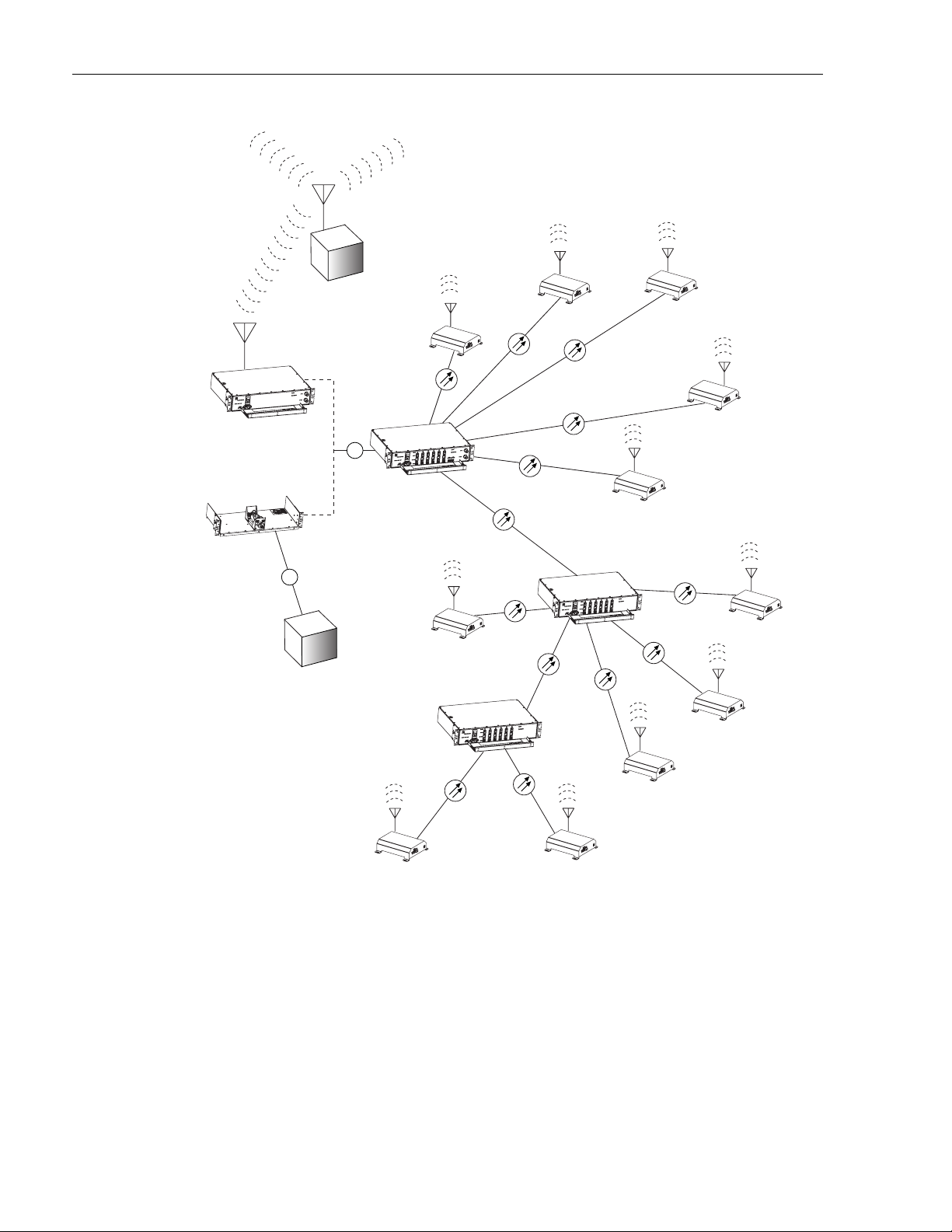
1.1 Basic System Components
The basic components of the Digivance ICS and their functions are shown in Figure 1. The
basic system consists of the Digital Host Unit (DHU), Digital Remote Unit (DRU), and when
additional capacity or longer fiber runs are required, the Digital Expansion Unit (DEU). In
addition, two accessory items, the High Power Conditioning Panel (HPCP) and the Remote
Interface Unit (RIU) may be used as needed to interface the DHU with the cellular system
Base Transceiver Station (BTS).
ADCP-75-130 • Issue 3C • August 2006
1.2 Interface With BTS
The DHU interfaces, either locally or remotely, with the BTS. As referenced in this
publication, the BTS could be either a microcell or a cell site base station. When the BTS is
co-located (microcell interface) with the DHU, a local interface over coaxial cable is possible.
An interface device, such as the HPCP, may be used to provide the proper input RF signal
level to the DHU. When the BTS is not co-located (cell site base station interface) with the
DHU, a remote interface using a donor antenna is required. An interface device, such as the
RIU, is used to provide the proper input and output RF signal levels between the donor
antenna and the DHU.
In the forward path, the DHU receives RF signals from the BTS. The DHU digitizes the RF
signals and then converts them to digital optical signals for transport to the DEU’s and
DRU’s. In the reverse path, the DHU receives digital optical signals from the DRU’s and
DEU’s. The DHU converts the optical signals back to the original RF signal format for the
interface with the BTS.
1.3 Interface With Cellular Phones
The DRU interfaces (through an external antenna) with the cellular phones. In the reverse
path, the DRU receives RF signals from each cellular phone. The DRU digitizes the RF
signals and then converts them to digital optical signals for transport to the DHU. In the
forward path, the DRU receives digital optical signals from the DHU. The DRU converts the
optical signals back to the original RF signal format for transmission to the cellular phones. A
small external antenna is connected to the DRU to transmit and receive RF signals to and from
the cellular phones.
© 2006, ADC Telecommunications, Inc.
Page 1
Page 12
ADCP-75-130 • Issue 3C • August 2006
HPCP
RIU
DRU
REMOTE
BTS
DRU
RF
RF
LOCAL
BTS
DHU
DRU
DEU
DRU
DRU
DRU
DRU
DRU
1.4 Digital Fiber Optic Transport
The DHU is connected to each DRU unit over a pair of multi-mode or single-mode
(depending on the type of optical transceiver specified) optical fibers. One fiber is used to
transport the forward path optical signal. The other fiber is used to transport the reverse path
optical signal. Because the optical signal is digital, no adjustments to the optical signal level
are required at the DRU or the DHU as long as the BER is adequate. Either 62.5 or 50 micron
core multi-mode optical fiber; or 9 micron core single-mode optical fiber may be used for the
DEU
DRU
DRU
DRU
Figure 1. System Overview Functional Block Diagram
16417-B
Page 2
© 2006, ADC Telecommunications, Inc.
Page 13

optical transport connection. With 62.5 micron core multi-mode fiber , the optical path may be
up to 500 meters in length. With 50 micron core multi-mode fiber, the optical path may be up
to 750 meters in length. With 9 micron core single-mode fiber, the optical path may be up to
10 kilometers in length. Single- and multi-mode fibers may be used in the same system. The
optical fibers must be terminated with duplex LC connectors for connection with the DHU,
DEU’s and DRU’s.
1.5 Capacity for Expansion and Extended Runs
The DEU enables 6-way expansion of any optical port. This makes it possible to add more
DRU’s without having to install additional DHU’s. Each DHU is equipped with six optical
ports. If more than six DRU’s are required by the application, a DEU may be connected to one
of the DHU optical ports which expands that port to six ports. If still more optical ports are
required, then a second DEU may be connected to the DHU; or a second DEU may be
connected to the first DEU. The ability to cascade DEU’s in parallel or in series provides
unlimited flexibility. It is physically possible to connect an unlimited number DRU’s to the
DHU through the installation of DEU’s. The maximum number of DRU’s that can connected
to the DHU is limited only by the cumulative noise effect caused by antenna combining.
ADCP-75-130 • Issue 3C • August 2006
1.6 Power Requirements
The DHU, DEU, and RIU are each powered by 120–240 VAC, 50/60 Hz, 2 Amp power which
is supplied through a standard three-conductor 120 VAC power cord. The DRU is powered by
34–48 VDC which is supplied by either the DHU, DEU, or an AC/DC wall-mount style
converter. When the DRU is powered by the DHU or DEU, the power is fed through a
category 3 or 5 cable terminated with male RJ-45 connectors.
1.7 Fault Detection and Alarm Reporting
LED indicators are provided on the front panel of the various units to indicate if the system is
normal or if a fault is detected. In addition, normally open and normally closed alarm contacts
(for both major and minor alarms) are provided at the DHU for connection to a customer
provided external alarm system. This could be a local system or automatic call-out system.
2 DIGTAL UNIT DESCRIPTION
This section provides a description of the functions and features provided by the units that comprise
the ICS system, a listing of terms used and their definition, and a table of specifications.
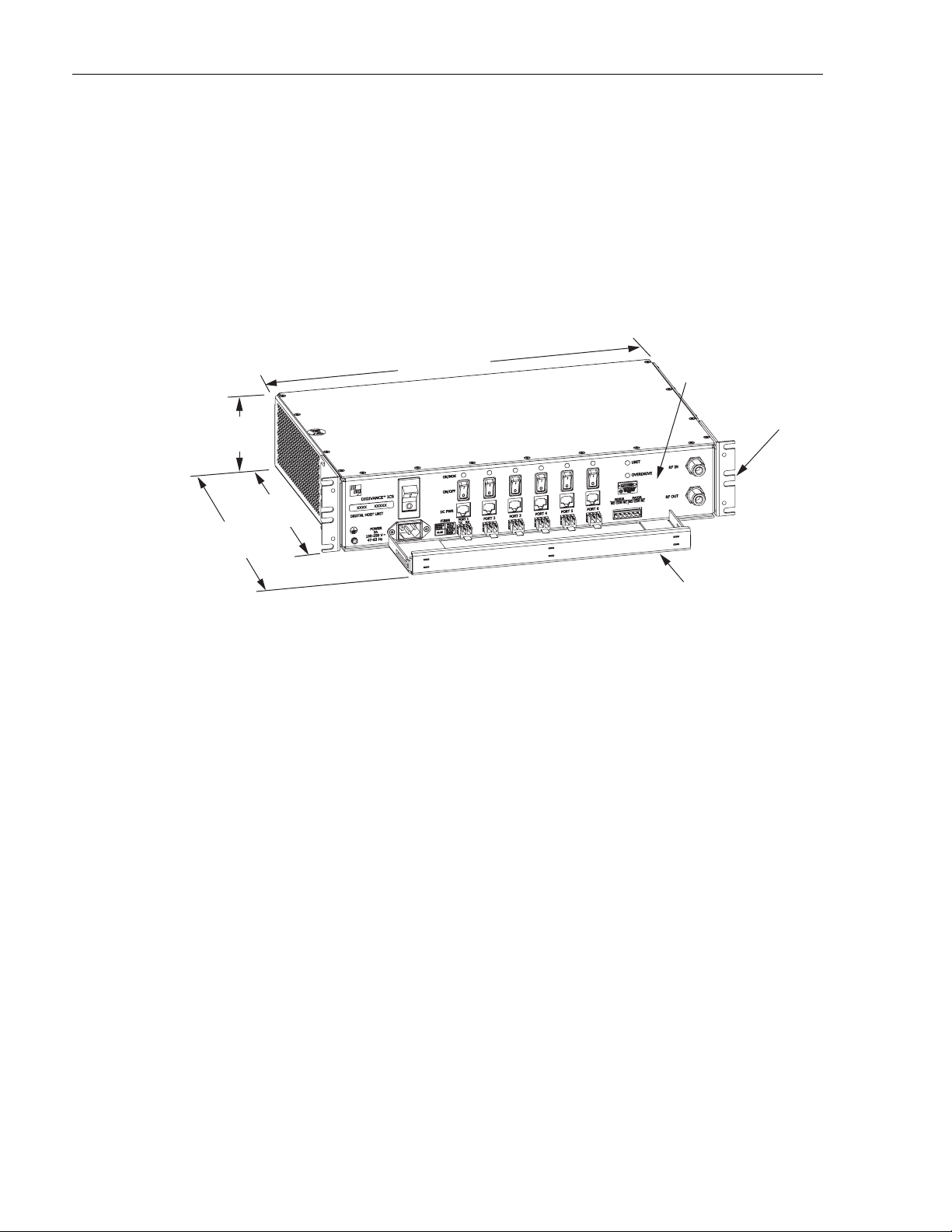
2.1 Digital Host Unit Description
The DHU, shown in Figure 2, serves as the BTS servicing unit for the Digivance ICS. The
DHU provides the following basic functions:
• RF inputs and outputs
• Optical interface to the DRU’s or DEU’s
© 2006, ADC Telecommunications, Inc.
Page 3
Page 14
ADCP-75-130 • Issue 3C • August 2006
• Digitizing of the cellular forward path RF signal
• Distribution of the digitized forward path RF signals into six digitized optical signals
• Conversion of up to six reverse path digitized optical signals to six digitized RF signals
• Combining of the six digitized RF signals into a single composite digitized RF signal
• Conversion of the combined digitized RF signal to a composite RF signal
• DC power for powering the DRU’s
• Relay contact closures to provide alarm information to an external alarm system
3.5 INCHES
(89 mm)
11.4 INCHES
(290 mm)
15.3 INCHES
(389 mm)
17.2 INCHES
(437 mm)
FRONT PANEL
MOUNTING
BRACKET
(BOTH SIDES)
17267-A
CABLE MANAGEMENT
TRAY
Figure 2. Digital Host Unit
2.1.1 Primary Components
The DHU consists of two electronic circuit board assemblies, a power supply assembly, and a
fan assembly that are mounted within a powder-coated sheet metal enclosure. The metal
enclosure provides a mounting point for the electronic assemblies, serves as a heat sink, and
controls RF emissions. Except for the fan units and optical transceivers, the DHU components
are not field replaceable. The DHU is designed for use within a non-condensing indoor
environment such as inside a wiring closet or cabinet. All controls, connectors, and indicators
are mounted on the DHU front panel for convenient access. Cable management functions for
the power and fiber optic cables are provided by a cable management tray that extends
outward from the DHU front panel.
2.1.2 Mounting
The DHU may be used in both rack-mount and wall-mount applications. For rack mount
applications, a pair of reversible mounting brackets is provided that allow the DHU to be
mounted in either a 19-inch or 23-inch EIA or WECO equipment rack. When rack-mounted,
the front panel of the DHU is flush with the front of the rack and the cable management tray
extends 3.9 inches (99 mm) beyond the front panel. For wall-mount applications, a pair of
holes is provided in the cable management tray which allow the DHU to be mounted on any
flat vertical surface. The DHU should be oriented with the front panel facing upward when
wall-mounted. Fasteners are provided for rack-mount applications.
Page 4
© 2006, ADC Telecommunications, Inc.
Page 15

ADCP-75-130 • Issue 3C • August 2006
2.1.3 Fault Detection and Alarm Reporting
The DHU detects internal circuitry faults and optical port faults. Various front panel Light
Emitting Diode (LED) indicators turn from green to red or yellow if a fault is detected or an
optical input is lost. A set of alarm contacts (normally open and normally closed) are also
provided for reporting an alarm to an external alarm system when a fault is detected. Both
major alarm (all fault conditions except high temperature) and minor alarm (high temperature
fault condition) contacts are provided.
2.1.4 RF Signal Connections
The RF signal connections with the BTS are supported through two N-type female connectors.
One connector is used for coaxial cable connection of the forward path RF signal. The other
connector is used for coaxial cable connection of the reverse path RF signal. In most
installations, the DHU will not connect directly to the BTS but will be connected to an
interface device such as the RIU or the HPCP. Additional information concerning the DHU to
BTS interface is provided in the Digivance ICS Remote Interface Unit User Manual (ADCP75-178) and in the Digivance ICS 800 and 1900 MHz High Power Conditioning Panel User
Manual (ADCP-75-175).
Maximum output at the DRU antenna port is obtained when the level of the composite
forward path RF signal input to the DHU is 1 dB below the DHU overdrive level. The
maximum signal level the DHU will accept is determined by the DHU overdrive limiter. If the
input signal level is above a specified level, the overdrive limiter will incrementally insert
attenuation. The overdrive limiter protects the system against excessive inputs but does not
function during normal operation. The level of the RF signal output at the DRU is dependent
on the modulation protocol and the number of carriers.
2.1.5 Optical and Electrical Connections
The optical and electrical connections with the DRU’s and DEU’s are supported by six optical
and six electrical ports. Each optical and electrical port consists of a status LED, an RJ-45 DC
power jack, a port enabled/disable switch, and a small form factor LC-type optical transceiver
(available separately). Each transceiver is color-coded to identify whether it supports singlemode (blue) or multi-mode (black/beige) fiber. An optical port may be connected to a DRU, a
DEU, or not used. An electrical port may be connected to a DRU or not used. Unused ports
are disabled via the corresponding port enable/disable switch. When disabled, the port LED is
off, the alarm reporting function is disabled, the laser is off, and the DC power is off. Enabling
the enable/disable switch activates all functions. The modular optical transceivers are
accessory items and are field replaceable.
2.1.6 Powering
The DHU is powered by 120–240 VAC (50/60 Hz) power which is supplied through a
standard three-conductor 120 VAC power cord. The power cord is provided with the DHU
and is 98 inches (2.5 meters) long. A resetable circuit breaker/On-Off switch is provided at the
unit front panel. The switch applies power to the DHU internal power supply.
© 2006, ADC Telecommunications, Inc.
Page 5
Page 16

ADCP-75-130 • Issue 3C • August 2006
2.1.7 Cooling
Continuous air-flow for cooling is provided by dual fans mounted on the right side of the
housing. A minimum of 3 inches (76 mm) of clearance space must be provided on both the
left and right sides of the DHU for air intake and exhaust. An alarm is provided that indicates
if a high temperature condition (>50º C/122º F) occurs. The fans may be field-replaced if
either fan fails.
2.1.8 User Interface
The DHU user interface consists of the various connectors, switches, terminals, and LEDs that
are provided on the DHU front panel. The DHU user interface points are described in Table 1
and indicated in Figure 3.
Table 1. Digital Host Unit User Interface
REF
No.
1
2 POWER 3-wire AC power
USER INTERFACE
DESIGNATION
DEVICE
FUNCTIONAL
DESCRIPTION
Ground stud Used for connecting a grounding cable to
the DHU chassis.
Used for connecting the AC power cord.
cord connector
3 I/O I/O rocker switch/
circuit breaker
4 OK/NOK (Ports 1–6) Multi-colored LED
(Red/Green/Yellow)
Provides AC power On/Off control and
AC power over current protection.
Indicates if the DRU or remote DEU connected
to the optical port is normal or faulty or if the
reverse path optical input from the DRU or
remote DEU is normal or lost. (see Note)
5 ON/OFF (Ports 1–6) I/O rocker switch Enables or disables corresponding
electrical and optical ports.
6 DC PWR (Ports 1–6) RJ-45 jack (female) Used for connecting a DRU cat 3 or 5 power
cable to the designated DC power jack.
7 FIBER (Ports 1–6) LC-type optical
transceiver
Used for connecting each DEU or DRU
forward path and reverse path optical fibers
to the designated optical port.
8 UNIT Multi-colored LED
(Red/Green/Yellow)
9 OVERDRIVE Multi-colored LED
(Red/Green/Yellow)
Indicates if the DHU is normal or faulty.
(see Note)
Indicates when the forward path RF input
power is overdriving the DHU digitizing
circuitry. (see Note)
10 MAJOR MINOR Screw-type terminal
connector
(14–26 AWG)
Used for connecting an external alarm system
to the DHU. Includes normally open (NO),
normally closed (NC), and common (COM)
wiring connections.
11 RF IN N-type female RF
coaxial connector
12 RF OUT N-type female RF
coaxial connector
Used for connecting the forward path RF
coaxial cable to the DHU.
Used for connecting the reverse path RF
coaxial cable to the DHU.
Note: A more detailed description of LED operation is provided in Section 5.
Page 6
© 2006, ADC Telecommunications, Inc.
Page 17

ADCP-75-130 • Issue 3C • August 2006
(1) GROUND
STUD
NOTE: SHOWN WITHOUT
CABLE MANAGEMENT TRAY
(3) AC POWER
ON/OFF SWITCH
(2) AC POWER CORD
CONNECTOR
(4) OPTICAL PORT
(6) ELECTRICAL PORT
DC POWER JACK
2.2 Digital Remote Unit Description
The DRU, shown in Figure 4, serves as the remote interface unit for the Digivance ICS. The
DRU provides the following basic functions:
• RF interface to the cellular users via an external antenna
• Optical interface to the DHU or DEU
• Conversion of the forward path digitized optical signal to a digitized RF signal
• Conversion of the digitized forward path RF signal to the original cellular RF signal
• Digitizing of the cellular reverse path RF signal
• Conversion of the digitized reverse path RF signal to a digital optical signal output
• Transports alarm status over the reverse path optical fiber
LED INDICATOR
(6 PLACES)
(6 PLACES)
(5) OPT/ELEC PORT
ENABLE/DISABLE
SWITCH (6 PLACES)
(7) OPTICAL PORT
OPTICAL TRANSCEIVER
TX-LEFT - RX-RIGHT
(6 PLACES)
(10) ALARM
CONNECTOR
RECEPTACLE
Figure 3. Digital Host Unit User Interface
(8) UNIT LED
INDICATOR
(11) RF INPUT
CONNECTOR
(9) OVERDRIVE
LED
INDICATOR
(12) RF OUTPUT
CONNECTOR
17264-A
2.1 INCHES
(53 mm)
7.3 INCHES
(185 mm)
7.0 INCHES
(178 mm)
Figure 4. Digital Remote Unit
FRONT PANEL
MOUNTING FOOT
(EACH CORNER)
17268-A
© 2006, ADC Telecommunications, Inc.
Page 7
Page 18

ADCP-75-130 • Issue 3C • August 2006
2.2.1 Primary Components
The DRU consists of an electronic circuit board assembly that is mounted within a powdercoated sheet metal enclosure. The metal enclosure provides a mounting point for the
electronic assembly, serves as a heat sink, and controls RF emissions. Except for the optical
transceiver, the DRU components are not field replaceable. The DRU is designed for use
within a non-condensing indoor environment such as inside a building. All controls,
connectors, and indicators (except the SMA antenna connector) are mounted on the DRU front
panel for convenient access.
2.2.2 Mounting
The DRU is equipped with four integral mounting feet that allow it to be mounted on any flat
horizontal or vertical surface. A typical location for mounting the DRU would be on a ceiling
or a wall. Slots are provided in the mounting feet for securing the DRU to the mounting
surface.
2.2.3 Fault Detection
The DRU detects internal circuitry faults or loss of system inputs. A front panel LED indicator
turns from green to red when a fault condition is detected or when the optical input is lost. The
DRU sends the fault information to the DHU or DEU over the reverse path optical fiber. A
corresponding port LED at the DHU or DEU turns from green to red when the DRU reports a
fault.
2.2.4 Antenna Connection
The RF signal interface between the DRU and the cellular users is provided through an
external antenna. An SMA connector is provided for connecting the DRU to the antenna. The
antenna must be ordered separately. Several types of antennas with various RF propagations
are available. Non-ADC antennas may also be used with the DRU to meet various application
requirements but must comply with equipment authorization for RF exposure compliance.
2.2.5 Optical Port
The DRU uses a small form factor LC-type optical transceiver for connecting the optical
fibers. Each transceiver is color-coded to identify whether it supports single-mode (blue) or
multi-mode (black/beige) fiber. Depending on the application requirements, the optical port
may be connected to either a DHU or a DEU. The modular optical transceiver is an accessory
item and is field replaceable.
2.2.6 Powering
The DRU is equipped with a female RJ-45 jack that provides a connection point for the DC
power cable. The DRU is powered by 34–48 VDC power which is supplied through the RJ-45
connector. Power to the DRU may be supplied by the DHU, DEU, or by a 120 VAC to 48
Page 8
© 2006, ADC Telecommunications, Inc.
Page 19

ADCP-75-130 • Issue 3C • August 2006
VDC power converter (available separately as an accessory item) plugged into a properly
grounded 120 VAC outlet. The AC/DC converter is a UL Listed stand-alone Limited Power
Supply (LPS) unit with a rated output of 48 VDC at 1.2 Amps. When powered by the DHU or
DEU, a category 3 or 5 twisted-pair cable terminated with RJ-45 connectors is required.
2.2.7 Cooling
The DRU is cooled by natural convection air-flow. The DRU mounting feet are designed to provide
clearance under the unit so that air can enter the DRU enclosure from the bottom and exit through
the top. A minimum clearance of 3 inches (76 mm) must be provided on all sides of the DRU
(except the bottom) to ensure there is adequate air circulation for cooling. In addition, at least one
surface of the DRU installation area must be open to the interior of the building.
2.2.8 User Interface
The DRU user interface consists of the connectors and LED that are provided on the DRU
front and rear panels. The DRU user interface points are described in Table 2 and indicated in
Figure 5.
Table 2. Digital Remote Unit User Interface
REF
No.
1 STATUS Multi-colored LED
USER INTERFACE
DESIGNATION
DEVICE
(Red/Green/Yellow)
FUNCTIONAL
DESCRIPTION
Indicates if the status of the DRU is normal
or faulty or if the forward path optical input
is normal or lost. (see Note)
2 48 VDC RJ-45 jack (female) Used for connecting a DC power cable.
3 FIBER
TX RX
4 – SMA-type coaxial
LC-type optical
transceiver
connector (female)
Used for connecting the forward path and
reverse path optical fibers.
Used for connecting the antenna coaxial
cable lead.
Note: A more detailed description of LED operation is provided in Section 5.
(2) 48 VDC POWER
CONNECTOR
(3) FIBER LINK
OPTICAL ADAPTERS
TX-LEFT - RX-RIGHT
(1) STATUS LED
REAR VIEWFRONT VIEW
(4) ANTENNA CONNECTOR
Figure 5. Digital Remote Unit User Interface
© 2006, ADC Telecommunications, Inc.
17269-A
Page 9
Page 20

ADCP-75-130 • Issue 3C • August 2006
2.3 Digital Expansion Unit Description
The DEU, shown in Figure 6, serves as a service expansion unit and line extender for the
Digivance ICS. The DEU provides the following basic functions:
• Optical interface to the DHU and up to six DRU’s or DEU’s
• Conversion of the forward path digitized optical signal to an electrical bit stream
• Splitting of the electrical bit stream into six separate bit streams
• Conversion of the six forward path electrical bit streams into six digital optical signals
• Conversion of up to six reverse path digital optical signals into six serial bit streams
• Combining of the six reverse path serial bit streams into a single digital composite signal
• Conversion of the single digital composite signal to a digital optical signal
• DC power for powering the DRU’s
• Alarm transport via the optical fibers
3.5 INCHES
(89 mm)
17.2 INCHES
(437 mm)
FRONT PANEL
MOUNTING
BRACKET
(BOTH SIDES)
11.4 INCHES
(290 mm)
15.3 INCHES
(389 mm)
CABLE MANAGEMENT
17270-A
TRAY
Figure 6. Digital Expansion Unit
2.3.1 Primary Components
The DEU consists of two electronic circuit board assemblies and a power supply that are
mounted within a powder-coated sheet metal enclosure. The metal enclosure provides a
mounting point for the electronic assemblies and serves as a heat sink. Except for the fan units
and optical transceivers, the DEU components are not field replaceable. The DEU is designed
for use within a non-condensing indoor environment such as inside a wiring closet or cabinet.
All controls, connectors, and indicators are mounted on the DEU front panel for convenient
access. Cable management functions for the power and fiber optic cables are provided by a
cable management tray that extends outward from the DEU front panel.
2.3.2 Mounting
The DEU may be used in both rack-mount and wall-mount applications. For rack mount
applications, a pair of reversible mounting brackets is provided that allows the DEU to be
Page 10
© 2006, ADC Telecommunications, Inc.
Page 21

ADCP-75-130 • Issue 3C • August 2006
mounted in either a 19-inch or 23-inch EIA or WECO equipment rack. When rack-mounted,
the front panel of the DEU is flush with the front of the rack and the cable management tray
extends 3.9 inches (99 mm) beyond the front panel. For wall-mount applications, a pair of
holes is provided in the cable management tray which allow the DEU to be mounted on any
flat vertical surface. The DEU should be oriented with the front panel facing upward when
wall-mounted. Fasteners are provided for rack-mount applications.
2.3.3 Fault Detection
The DEU detects internal circuitry faults or loss of system inputs. Various front panel Light
Emitting Diode (LED) indicators turn from green to red or yellow when a fault is detected or
when an optical input is lost. The DEU transports the fault information to the DHU or
supporting DEU over the reverse path optical fiber. A corresponding port LED at the DHU or
DEU turns from green to red when the DEU reports a fault.
2.3.4 Optical and Electrical Connections
The optical and electrical connections with the DRU’s and DEU’s are supported by six optical
and six electrical ports. Each optical and electrical port consists of a status LED, an RJ-45 DC
power jack, a port enable/disable switch, and a small form factor LC type optical transceiver
(available separately). Each transceiver is color-coded to identify whether it supports singlemode (blue) or multi-mode (black/beige) fiber. An optical port may be connected to a DRU, a
DEU, or not used. An electrical port may be connected to a DRU or not used. Unused ports are
disabled via the corresponding port enable/disable switch. When disabled, the port LED is off,
the alarm reporting function is disabled, the laser is off, and the DC power is off. Enabling the
enable/disable switch activates all functions. The DEU also provides one optical port (designated
as the host port ) for the optical interface with the DHU or a supporting DEU. The modular
optical transceivers are available as accessory items and are field replaceable.
2.3.5 Powering
The DEU is powered by 120–240 VAC (50/60 Hz) power which is supplied though a standard
three-conductor 120 VAC power cord. The power cord is provided with the DEU and is 98
inches (2.5 meters) long. A resetable circuit breaker/On-Off switch is provided at the unit
front panel. The switch applies power to the DEU internal power supply.
2.3.6 Cooling
Continuous air flow for cooling is provided by dual fans mounted on the right side of the sheet
metal housing. A minimum of 3 inches (76 mm) of clearance space must be provided on both
the left and right sides of the DEU for air intake and exhaust. An alarm is provided that
indicates if a high temperature condition (>50º C/122º F) occurs. The fans may be fieldreplaced if either unit fails.
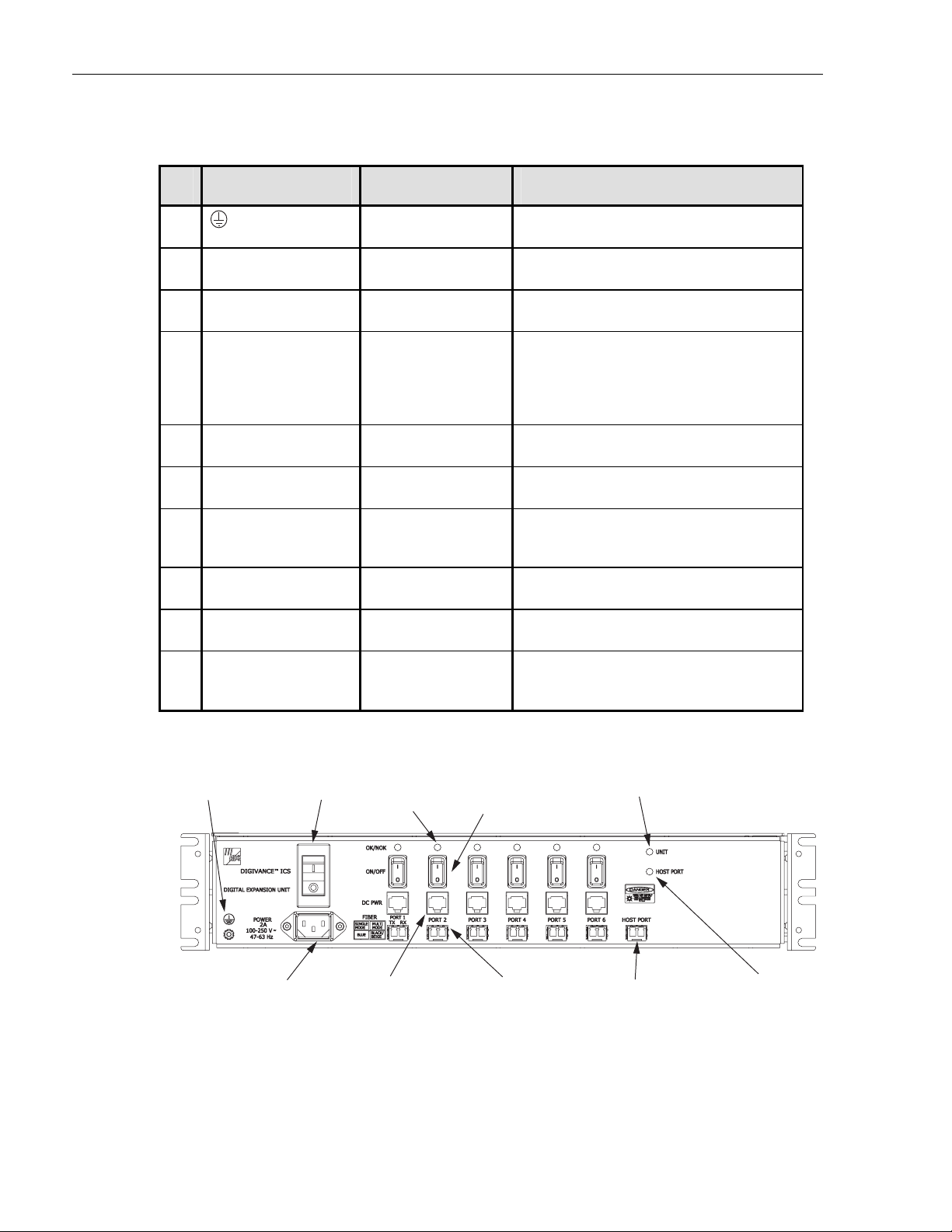
2.3.7 User Interface
The DEU user interface consists of the various connectors, switches, and LEDs that are
provided on the DEU front panel. The DEU user interface points are described in Table 3 and
indicated in Figure 7.
© 2006, ADC Telecommunications, Inc.
Page 11
Page 22
ADCP-75-130 • Issue 3C • August 2006
Table 3. Digital Expansion Unit User Interface
REF
No.
1
2 POWER 3-wire AC power
USER INTERFACE
DESIGNATION
DEVICE
FUNCTIONAL
DESCRIPTION
Grounding stud Used for connecting a grounding cable to
the DEU chassis.
Used for connecting the AC power cord.
cord connector
3 I/O I/O rocker switch/
circuit breaker
4 OK/NOK (Ports 1–6) Multi-colored LED
(Red/Green/Yellow)
Provides AC power On/Off control and
AC power over current protection.
Indicates if the DRU or remote DEU
connected to the optical port is normal or
faulty or if the reverse path optical input
from the DRU or remote DEU is normal
or lost. (see Note)
5 ON/OFF (Ports 1–6) I/O rocker switch Enables or disables corresponding
electrical and optical ports.
6 DC PWR (Ports 1–6) RJ-45 jack (female) Used for connecting a DRU cat 3 or 5 power
cable to the designated DC power jack.
7 FIBER (Ports 1–6) LC-type optical
transceiver
Used for connecting each DRU or remote
DEU forward path and reverse path optical
fiber to the designated optical port.
8 HOST PORT LC-type optical
transceiver
9 UNIT Multi-colored LED
(Red/Green/Yellow)
10 HOST PORT Multi-colored LED
(Red/Green/Yellow)
Used for connecting the DHU or supporting
DEU forward path and reverse path optical fiber.
Indicates if the DEU is normal or faulty.
(see Note)
Indicates if the forward path optical input
from the DHU or supporting DEU is
normal or lost. (see Note)
Note: A more detailed description of LED operation is provided in Section 5.
(1) GROUNDING
STUD
NOTE: SHOWN WITHOUT
CABLE MANAGEMENT TRAY
Page 12
© 2006, ADC Telecommunications, Inc.
(3) AC POWER
ON/OFF SWITCH
(2) AC POWER CORD
CONNECTOR
(4) OPTICAL PORT
LED INDICATOR
(6 PLACES)
(6) ELECTRICAL PORT
DC POWER JACK
(6 PLACES)
(5) OPT/ELEC PORT
ENABLE/DISABLE
SWITCH (6 PLACES)
(7) OPTICAL PORT
OPTICAL TRANSCEIVER
TX-LEFT - RX-RIGHT
(6 PLACES)
(9) UNIT LED
INDICATOR
(8) HOST PORT
OPTICAL TRANSCEIVER
TX-LEFT - RX-RIGHT
Figure 7. Digital Expansion Unit User Interface
(10) HOST PORT
LED
INDICATOR
17266-A
Page 23

2.4 Terms and Definitions
Refer to Table 4 for a listing of the terms used in this manual and their definition.
TERM DEFINITION
Alarm Response The response to an alarm input.
Base Transceiver Station The radio equipment that transmits and receives the voice and control
Composite Signal A signal that is the sum of several signals.
Digital Expansion Unit The unit that extends a single optical interface to multiple optical
Digital Host Unit The unit that converts and provides the digital source signal to all DEU’s
Digital Remote Unit The unit that interfaces the in-building user to the Digivance optical transport.
Digitized RF Signal The RF signal in a digitized form.
Forward Path Signal A signal that travels from the base station to the cell phone.
Major Alarm An alarm condition that applies when any fault (except high
Minor Alarm The alarm condition that applies when a high temperature condition
Mute To force a forward path RF signal to a “no signal” state.
Normal State The operating state after power-up is completed and no faults are detected.
Port An RF, optical, or electrical interface point.
Port Alarm A fault that affects only the unit or units connected to that port.
Power-Up State The period between the application of power to a unit and the normal
Reverse Path Signal A signal that travels from one or more cell phones to the base station.
Transport Alarm Signal An alarm signal transported over the reverse path optical fiber.
Unit Alarm A fault within a unit that usually affects all connected ports.
ADCP-75-130 • Issue 3C • August 2006
Table 4. Terms and Definitions
channels to and from the cellular handsets.
interfaces or that extends an optical run.
and DRU’s and converts summed inputs from DEU’s and DRU’s.
temperature) occurs.
occurs. (> 50º C/122º F)
Indicates no optical input to port.
state. This period includes time for circuit stabilization and
initialization operations.
2.5 Specifications
Refer to Table 5 for the Digivance ICS system specifications. All specifications apply after a
five minute warm-up period.
© 2006, ADC Telecommunications, Inc.
Page 13
Page 24

ADCP-75-130 • Issue 3C • August 2006
PARAMETER SPECIFICATION REMARKS
Table 5. System Specifications
Optical – All Units
Fiber type
Multi-mode: 50 or 62.5 micron core
Two fibers per transport link
Single-mode: 9 micron core
Maximum fiber length
for guaranteed
performance
500 m (1,641 ft)
750 m (2461 ft)
10 km (32,808 ft)
With 62.5 micron core MM fiber
With 50 micron core MM fiber
With 9 micron core SM fiber
Optical output power –10 to –3 dBm
Optical wavelength 850 nm for multi-mode use
1310 nm for single-mode use
Environmental
Operating temperature
0º to 50º C (32º to 122º F)
Storage temperature –30º to +70º C (–22 to 158º F)
Humidity No condensation
Weather resistance NEMA 1, IEC 529 IP30 Indoor installation only
Airborne contaminants
(DRU only)
At or below levels established in Telecordia Standard, GR-63-CORE,
Network Equipment-Building System (NEBS) Requirements: Physical
Protection, Section 4.5 Airborne Contaminants, Table 4-11, Indoor
Contaminant Levels.
RF Forward Path
System bandwidth
25 MHz
800 MHz (A and B bands) US Cellular 869 to 894 MHz
Output power See Table 6 Maximum composite output signal
requires maximum input signal
Gain +33 dB nominal At room temperature
Gain variation < 6 dB
< 1.5 dB variation per 1.25 MHz
CDMA channel
Over frequency, temperature, and
unit to unit. May have up to 2 dB
variation at upper band edge.
OIP3 +35 dBm typical At max. composite output power
CDMA ACPR1 < –45 dBc
Spurious Output < –40 dBm
Maximum RF input
signal level (composite)
RF Reverse Path
System bandwidth
Approximately –10 dBm Will vary depending on access protocol
and number of carriers
25 MHz
800 MHz (A and B bands) US Cellular 824 to 849 MHz
Gain +10 dB nominal
Gain Variation < 6 dB
< 1.5 dB variation per 1.25 MHz
CDMA channel
Automatic Gain Limiting Enabled for composite RF input
>
–40 dBm
Over frequency, temperature, and
unit to unit.
Prevents A/D saturation with large
inputs.
Page 14
© 2006, ADC Telecommunications, Inc.
(continued)
Page 25

ADCP-75-130 • Issue 3C • August 2006
Table 5. System Specifications, continued
PARAMETER SPECIFICATION REMARKS
Noise Figure < 8 dB + 10 log N where N = # of
remotes
DHU RF output signal
–30 dBm maximum With a –40 dBm composite
level
Physical/Electrical – DHU
Weight
18.5 lbs (8.4 kg)
< 8 dB typical. See Note at end of
table.
maximum input signal at the DRU
RF connection Type N Female
Alarm connection Screw terminals (14–26 AWG) NO, NC, and COM (form C relay
contacts)
Optical connection Duplex LC transceiver
DC power output
RJ-45 Female
connection
Power input 120–240 VAC, 50/60 Hz
AC power connection IEC 320 Male
Power consumption 250 W Maximum
Current rating 2 Amps at 120 VAC
Physical/Electrical – DEU
Weight
18.5 lbs (8.4 kg)
Optical connection Duplex LC transceiver
DC pwr output connection RJ-45 Female
Power input 120–240 VAC, 50/60 Hz
AC power connection IEC 320 Male
Power consumption 250 W Maximum
Current rating 2 Amps at 120 VAC
Physical/Electrical – DRU
Weight
1.5 lbs (708 g)
RF connection SMA Female
Antenna types Ceiling mount omni directional
90º directional panel
Ceiling mount hallway
2.5 dBi gain
7.5 dBi gain
4 dBi gain
Optical connection Duplex LC transceiver
DC pwr input connection RJ-45 Female
Power input 34 to 48 VDC
DC power cable length
(Cat-3 or -5 cable)
500 meters (1,641 ft) maximum Any distance beyond 500 meters
requires alternate power sourcing
Power consumption 17 W Typical
Current rating 400 mA at 48 VDC
Note : The noise from all remotes is added at the host. Given N units with identical gain and noise, the formula
applies exactly. Slight unit to unit noise figure and gain variations make this a very useful approximation.
© 2006, ADC Telecommunications, Inc.
Page 15
 Loading...