

Page 1

Appendix
– Cables, Connectors, and
A
Accessories
This section provides information about cables, connectors, and accessories that an
LGCell application might require. LGC Wireless can provide these components, or
the customer can. If the customer provides them, they must be on-site when LGC
Wireless personnel arrive.
Information in this section includes the following topics:
• A description of the cables and connectors needed for the installation
• Relative system gain over varying cable lengths
Contents
Appendix A – Cables, Connectors, and Accessories
Cables and Connectors. . . . . . . . . . . . . . . . . . . . . . . . . . . . . . . . . . . . . . . . . . . . . . 3
LGCell Accessories . . . . . . . . . . . . . . . . . . . . . . . . . . . . . . . . . . . . . . . . . . . . . . . . 7
Page 2

A-2 Appendix A – Cables, Connectors, and Accessories
Page 3
Cables and Connectors
The following cables and connectors are required for connecting
not provided with the LGC
prior to the LGC
and connectors.
Determine which cables (and their length) and connectors you need, then order
them through a cable vendor or installer.
installation. LGC wireless can provide and install these cables
ell
equipment and must be on site or installed at the site
ell
LGCell.
Coaxial Cable – RF Transmission
Standard Coaxial Cable for Duplex RF Connections
• Connects the Main Hub to a roof-mounted antenna, repeater, or duplex MBS.
• Provides bi-directional downlink and uplink transmission with one cable for
duplex RF connections.
Standard Coaxial Cable for Simplex RF Connections
• Connects a Main Hub to a simplex MBS, a simplex roof-mounted antenna, or
repeater.
• Provides unidirectional downlink and uplink signals on separate cables for
simplex RF connections.
They are
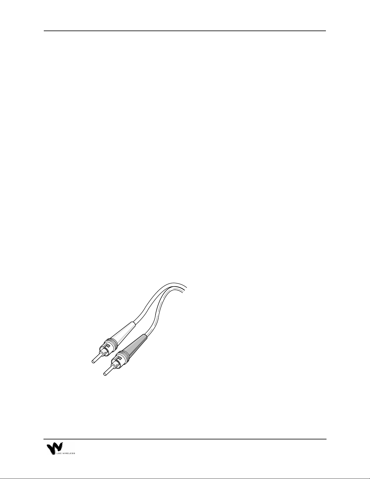
MMF Cable with ST-Connectors –
RF Transmission (Vertical Run)
Standard Multi-Mode Fiber Optic Cable
• Connects Main Hub to Expansion Hubs
a028
• Transmits (downlink) and receives (uplink)
MMF
Cable
• Accommodates distances up to 1 km.
cellular and/or PCS signals.
A-3
Page 4

UTP/STP Cable with RJ-45 connectors –
RF Transmission (Horizontal Run)
RJ-45
Connector
Standard Category 5 Unshielded or Shielded Twisted
Pair
• Connects the Expansion Hub to the RAUs.
• Transmits (downlink) and receives (uplink) cellular
and PCS signals.
UTP/STP
Cable
• Delivers electrical power to RAUs.
a029
• Accommodates distances up to 60 meters.
LGC Wireless recommends plenum-rated CAT 5 UTP/STP cable and connectors.
A-4 Appendix A – Cables, Connectors, and Accessories
Page 5
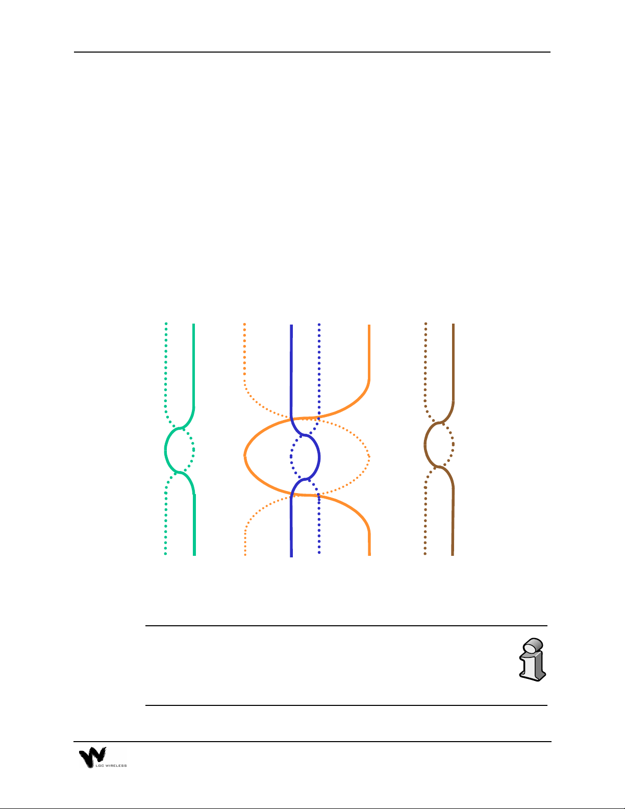
Unshielded Twisted Pair Cable Termination
All UTP (Unshielded Twisted Pair) shall be terminated according to the TIA/EIA
568-A standard. The following diagram describes how the four pairs should be
terminated.
Top View of the Wiring Map for Category 5 (CAT 5) UTP Cable
(TIA/EIA 568-A Standard)
Straight Connect
12 3 45 6 78
Green/
White
Green Orange
The UTP/STP cable can be any length from 10 meters up to 60 meters. (Per
TIA/EIA specifications, UTP/STP cable must be at least 10 meters.) For
cables longer than 60 meters, system specifications are slightly degraded.
When using high quality UTP/STP cable, lengths up to 60 meters can be
used without degrading system performance.
Orange/
White
Blue
Blue/
White
Brown/
White
Brown
A-5
Page 6

The next two tables show how system gain on the uplink and downlink vary as a
function of cable length (horizontal run, measured with 1 km of Multi-Mode Fiber).
LGCell System Gain vs. UTP/STP Cable Length (800 MHz, iDEN, 900 MHz)
UTP Cable Length (feet) Relative System Uplink and Downlink Gain (dB)
0 No change in gain
10 No change in gain
20 No change in gain
30 No change in gain
40 No change in gain
50 No change in gain
60 No change in gain
70 No change in gain
80 No change in gain
90 No change in gain
100 No change in gain
110 No change in gain
120 No change in gain
130 No change in gain
140 No change in gain
150 No change in gain
160 No change in gain
170 No change in gain
180 -0.6
190 -1.3
200 -2.0
210 -2.7
220 -3.4
230 -4.1
240 -4.8
250 -5.5
260 -6.2
270 -6.9
280 -7.6
290 -8.3
300 -9.0
310 -9.7
320 -10.4
330 -11.1
A-6 Appendix A – Cables, Connectors, and Accessories
Page 7

LGCell System Gain vs. UTP/STP Cable Length
for 1800 MHz or 1900 MHz
(Horizontal run, measured with 1 km of Multi-Mode Fiber)
UTP Cable Length (feet) Relative System Uplink and Downlink Gain (dB)
0 No change in gain
10 No change in gain
20 No change in gain
30 No change in gain
40 No change in gain
50 No change in gain
60 No change in gain
70 No change in gain
80 No change in gain
90 No change in gain
100 No change in gain
110 No change in gain
120 No change in gain
130 No change in gain
140 No change in gain
150 No change in gain
160 No change in gain
170 No change in gain
180 -0.6
190 -1.3
200 -2.0
210 -2.7
220 -3.4
230 -4.1
240 -4.8
250 -5.5
260 -6.2
LGC
ell
Accessories
LG
provides a full range of accessories that might be required for LG
Cell
applications. Please see your LG
for the accessory list.
Price Book or contact your account manager
Cell
Cell
A-7
Page 8

A-8 Appendix A – Cables, Connectors, and Accessories
Page 9

Appendix
This appendix is a summary of the TIA/EIA 568-A Commercial Building
Telecommunications Cabling Standard.
The TIA/EIA 568-A commercial building cabling standard addresses the need for
a common criterion covering cabling in commercial buildings. The standard was
drafted to ensure support for a wide variety of applications, devices, and vendor
products.
The TIA/EIA 568-A standard assures a flexible cabling scheme which permits the
planning and installation of communications cable without prior knowledge of the
user's needs. This is especially valuable for new building construction and
renovation where it is less costly and less disruptive to install a universal cabling
system prior to occupancy.
The need for a building cabling standard was recognized in the early 1980s. It
resulted from the changes brought on by new technologies. The purpose of the
original drafting committee was to provide a non-proprietary cabling system for
both new and existing facilities.
– TIA/EIA 568-A Cabling Standard
B
In 1985, the Computer Communications Industry Association approached the
Electronic Industry Association (EIA) in regard to the market's confusion over
cabling systems. The EIA and later its offspring, the Telecommunications Industry
Association (TIA), addressed this via technical working groups comprised of
industry participants. The resulting standard 568 addressed performance and safety
issues related to technology and utilized many recognized and proven standards.
The TIA/EIA 568-A standard defines the categories of UTP cabling, the categories
of connecting hardware, patch cables, and provides guidelines on cabling practices.
The TIA/EIA 568-A standard describes six sub-systems within a facility
telecommunications cabling system summarized below. (This is intended as a
summary only and is meant to provide a better comprehension of the standard. The
complete TIA/EIA 568-A standard is available for purchase. Call 1-800-854-7179.)
Page 10

Horizontal Wiring
The horizontal cable is the portion of the cabling system which extends from the
work area outlet to the telecommunications closet. The horizontal cabling is a star
topology, with a maximum cabling run of 90 meters (295 feet), independent of
media type.
Voice Data
4-pair 100 ohm UTP cable 4-pair 100 ohm UTP/STP
2-pair 150 ohm STA
62.5/125 µm fiber optic cable
The horizontal cable amounts to the greatest quantity of individual cables in the
building. Although the TIA/EIA 568-A standard helps limit cabling options,
consideration should be given to media type in order to support possible future
needs. The cable selected should accommodate more than one network planning
period.
Backbone Wiring
The backbone cabling provides the interconnection between the telecommunications closets and the equipment rooms and entrance facilities. The
backbone cabling is also a star topology with the maximum cable length being
media and applications dependent.
The backbone cable is typically second to horizontal cables in terms of amount of
cable deployed. The cable selected should accommodate a minimum of one to
several network planning periods.
B-2 Appendix B – TIA/EIA 568-A Cabling Standard
Page 11
Multi-Mode Optical Fiber Cable
62.5/125 micron Optical Fiber Cable
62.5/125 µm Optical Fiber Cable
3000m (9843 ft.)
HC
500m
(1640 ft.)
100Ohm UTP Cable for Voice
IC
2500m
(8202 ft.)
800m (2624 ft)
Maximum
TC
500m
(1640 ft.)
Maximum
HC Horizontal Cross-Connect MC Main Cross-Connect IC Intermediate Cross-Connect
Note 1
When the HC to IC distance is less than maximum,
the IC to MC distance for optical fiber can be
increased accordingly but the total distance from the
HC to the MC shall not exceed the maximum of
2000m (6560 ft.).
IC
300m
(984 ft.)
Note 2
MC
MC
HC
100Ohm UTP Cable for Data
HC
150Ohm STP-A Cable for Data
HC
Note 2
When the HC to IC distance is less than maximum,
the IC to MC distance for UTP cable can be
increased accordingly but the total distance from the
HC to the MC shall not exceed the maximum of
800 m (2624 ft). For voice applications only.
2000m (6560 ft.)
Maximum
500m
(1640 ft.)
Maximum
90m (295 ft)
Maximum
90m (295 ft)
Maximum
IC
MC
1500m
(4920 ft.)
Note 1
IC/
MC
IC/
MC
Work Area
The work area interconnects the horizontal cabling at the wall outlet to the desktop
devices. The maximum allowable distance for patch cables is three meters (9.8
feet), based on the cable being of the same type as the horizontal cable.
Telecommunications Closet
The telecommunications closet is the area in a building dedicated to
telecommunication equipment. The functions which take place in the closet include
the interconnection point between horizontal and backbone cabling systems, the
interconnection of two or more backbone cabling systems, and/or the
interconnection of the entrance facility to the overall telecommunications cabling
system.
B-3
Page 12

Equipment Room
The equipment room is the area in a building where telecommunications equipment
is located. Parts of or all of the telecommunications cabling system terminate here.
Entrance Facilities
The entrance facility is where outside telecommunications service enters the
building, and interconnects with the building's internal telecommunications
systems. In a campus or mul ti-building environment, t he entranc e facilit y may also
contain the building's backbone interconnects.
Unshielded Twisted Pair Cable Termination
All UTP (Unshielded Twisted Pair) shall be terminated according to the TIA/EIA
568-A standard.
B-4 Appendix B – TIA/EIA 568-A Cabling Standard
Page 13

Appendix
– Compliance Information
C
All LGCell systems comply with Optical Fiber Safety Standard IEC/EM60825-2.
The LGCell distributed antenna system is rated as a Class 1 laser hazard system. It
has an absolute maximum output power of -11.5 dBm at 1300 nanometers (nm).
There are no restriction on the location or use of an LGCell system. No special
precautions are required if standard work practices are followed. Additional
information on the safe use of optical fiber communications systems is at the end of
this appendix.
The following provides LGC Wireless’ LGCell system approval status for various
countries around the world. Some European countries require National Type
Approval to their national standards (such as Germany).
DAS9M-2-W:
Telecom: A200296L (BAPT 222 ZV 15/ETS 300 609-4) and ETS 300 609-4,
October 1998
EMC: EN 300 339, June 1998, EN 61009-4-6, 1996, and EN55022/CISPR
22 Class B
Safety: Power Supplies, Astec International Ltd., Model LPS 43, Universal
Micro Electronics Co. Ltd., Model UPO651S-02, and International
Power Sources, Inc., Model UPO651S-02 all have CB scheme
certifications.
Markings: The German Type Approval mark is required as well as the UK
approval number. The CE mark is also required.
DAS18M-2-W:
Telecom: ETS 300 609-4, October 1998
EMC: EN 300 339, June 1998
Safety: Power Supplies, Astec International Ltd., Model LPS 43, Universal
Micro Electronics Co. Ltd., Model UPO651S-02, and International
Power Sources, Inc., Model UPO651S-02 all have CB scheme
certifications.
Markings: The UK approval number and the CE mark are required.
Page 14

DAS8M-2-W:
Telecom: FCC: NOO-DAS800-1 (FCC Part 22.901d) Non-Broadcast
Transmitter
Industry Canada: 3077281151A for the “Cellular 800” (RSS128,
Issue 1)
EMC: FCC: Class A, Part 15, Subpart B
Industry Canada: Same as FCC
Safety: UL 1950, 3rd Edition and the cUL mark for the Canadian equivalent.
NEBS: This is a customer driven conformance certification and typically
desired of equipment that is intended to be installed in a Central
Office environment. LGC products are intended as Customer
Premise Equipment and it is not anticipated that they will be
installed in a Central Office environment, therefore NEBS
conformance certification has not been pursued at this time.
Markings: The FCC approval number and the FCC logo are required. The word
Canada followed by the Canadian approval number is required. The
UL mark is required.
DAS19M-2-W:
Telecom: FCC: NOO-DAS800-1 (FCC Part 24E) Distributed Antenna System
(Repeater)
Canada: 3077331163A for the “PCS 1900” (RSS-133, Issue 1)
EMC: FCC: Class A, Part 15, Subpart B
Industry Canada: Same as FCC
Safety: UL 1950, 3rd Edition and the cUL mark for the Canadian equivalent.
NEBS: This is a customer driven conformance certification and typically
desired of equipment that is intended to be installed in a Central
Office environment. LGC products are intended as Customer
Premise Equipment and it is not anticipated that they will be
installed in a Central Office environment, therefore NEBS
conformance certification has not been pursued at this time.
Markings: The FCC approval number and the FCC logo are required. The word
Canada followed by the Canadian approval number is required. The
UL mark is required.
C-2 Appendix C – Compliance Information
Page 15

FCC Regulatory Notice:
This device complies with Part 15 of the FCC Rules. Operation is subject to the
following two conditions:
• This device may not cause harmful interference.
• This device must accept any interference received, including interference that
may cause undesired operation.
Industry Canada Regulatory Notice:
This Class B (or Class A, if so indicated on the registration label) digital apparatus
meets the requirements of the Canadian Interference-Causing Equipment
Regulations.
Cet appareil numerique de la Classe B (ou Classe A, si ainsi indique sur l’etiquette
d’enregistration) respecte toutes les exigences du Reglement sur le Materiel
Brouilleur du Canada.
C-3
Page 16
C-4 Appendix C – Compliance Information
Page 17

C-5
Page 18

IEC/EN 60825-2 - Safe Use of Optical Fiber
Communication Systems
Part 2 of IEC 60825 provides requirements and specific guidance for the safe use of
optical fiber communications where optical power may be accessible at some
distance from the optical source. In this part of IEC 825, light emitting diodes
(LED’s) are included whenever the word “laser” is used.
Description of LG
The LG
A Main Hub, which is connected by dual mode fiber optic cables to one or more
Expansion Hubs. Each Expansion Hub is connected by UTP CAT 5 cable to a
Remote Antenna Unit. Because LED’s are used to send a signal over the fiber optic
cable, the LG
is a distributed antenna system. It consists of three main components.
Cell
Cell
System
is covered under the IEC 60825 specification.
Cell
Requirements under IEC 60825
Under IEC 60825, LGC Wireless is required to determine the Class of operation of
the LG
instructions that must be included in an operators manual as well as any warning
labels that may be required on the LG
The LG
3.2 enclosed system:
radiation is totally enclosed, by light proof cabinets, components, total internal
reflection or optical fiber cables and connectors.
3.3 end user:
the manner the system was designed to be used. The user cannot necessarily control
the power generated and transmitted within the system.
system, the Hazard level of the LG
Cell
system.
Cell
is covered only under these definitions of section 3 of 60825
Cell
A system in which, during normal operation, the optical
The person or organization using the optical fiber communication in
system and any special
Cell
.
3.4 hazard level 1:
communication system at which, under reasonably foreseeable circumstances,
human access to laser radi ation in excess of the accessible emission limits (AEL) of
class 1 for the applicable wavelengths and emission duration will not occur.
3.10 light emitting diode (LED):
to produce electromagnetic optical radiation in the wavelength range from 180nm
to 1mm. (The optical radiation is produced by the process of spontaneous emission,
although some stimulated emission may be present.)
3.13 location with controlled access:
housing (enclosure) is controlled and is accessible only to authorized persons who
have received adequate training in laser safety and servicing of the system involved.
Examples include optical cable ducts and switching centers.
C-6 Appendix C – Compliance Information
A hazard level 1 is allocated to any part within an optical fiber
Any semiconductor device which can be made
A location where access to the protective
Page 19

3.14 location with restricted access:
housing is restricted and not open to the public. Examples include industrial and
commercial premises, PBX rooms, computer system rooms, and optical test sets.
Distributed fiber networks may pass through unrestricted public areas, restricted
areas within premises, as well as controlled areas or they may be deployed entirely
within restricted business premises.
A location where access to the protective
3.18 optical fiber communication system:
generation, transference, and reception of optical radiation arising from lasers in
which the transference is by means of optical fiber for communication purposes.
3.19 reasonable foreseeable event:
circumstances can be predicted fairly accurately, and the occurrence of which is a
possibility. Examples of reasonably foreseea ble events might include the following:
fiber cable break, optical connector disconnection, operator error or inattention to
safe working practices. Reckless use or use for completely inappropriate purposes
is not to be considered as a reasonably foreseeable event.
An event, the occurrence of which under given
An engineered assembly for the
Installation Notes
The LGCell is covered under these parts of section 5 of 60825
5.2.1.3 Test Equipment:
system, only test equipment of laser Class 1 should be used.
5.2.1.5 Installation Rules:
optical fiber cable communication system should observe all rules, procedures and
practices established for the safe operation of optical fiber communication systems.
During installation or testing of an optical fiber cable or
Each person engaged in the installation or service of an
Evaluation of LGC System
The LGCell is covered under Annex A of 60825
The LG
communication system that would be safe under normal operating conditions
because the optical radiation is totally enclosed and contained under intended
operation. However, because of the extended nature of the system, the optical
power may be accessible a kilometer from the optical source. The LG
contains LED's, which are the source of radiation covered under IEC 825. Usually
a whole fiber optical communication system would not be classified under IEC 8252 in the same way required under IEC 825-1. This is because, under intended
operation, the optical power is totally enclosed, and it could be argued that an
interpretation of IEC 825-1 would give a class 1 to all systems, which may not
accurately reflect the hazard potential of some systems. If the emitter can be
operated separately, it should be classified according to IEC 825-1. However, the
power output level of the LG
1 hazard level even under 100% modulation conditions. The absolute maximum
allowed at 1300nm is +9.5 dBm. The absolute maximum accessible output of the
system is a self contained product that contains an optical fiber
Cell
system is so low that it always falls into the c lass
Cell
Cell
system
C-7
Page 20

LG
location of use of the LG
fiber optic system is -11.5 dBm. Therefore there is no restriction as to
Cell
Cell
Suggested Work Practices
system and there is no labeling requirement.
The LG
is covered under these parts of section D7 of 60825
Cell
The following working practices are suggested for working on the LG
Viewing Fiber:
•
Do not stare with unprotected eyes at the connector ends of the
fibers or the ports of the hub.
Test Fibers Cables:
•
When using test fiber optical cables, the optical power
source shall be the last to be connected and the first to be disconnected.
Fiber ends:
•
Any unconnected fiber ends should be covered with an approved
cap. Do not use tape.
Broken Fiber Cables:
•
Do not stare with unprotected eyes at any broken ends
of the fibers. Report and have any broken fiber cables replaced.
Cleaning:
•
Modification:
•
Use only approved methods for cleaning optical fiber connectors.
Do not make any unauthorized modifications to this fiber
optical system of associated equipment.
Live work:
•
Signs:
•
Test Equipment:
•
No warning signs are required.
Live work is permitted on the LG
Use class 1 test equipment.
as it is a class 1 hazard.
Cell
Cell
system:
C-8 Appendix C – Compliance Information
Page 21

Appendix
– Services
D
This appendix gives an overview of services that LGC Wireless provides.
LGC Wireless offers a full range of professional services to ensure cost-effective
and timely deployment of wireless networks. The seasoned staff of dedicated
service professionals at LGC Wireless combine wireless system design and
implementation expertise with a commitment to customer satisfaction unequalled
in the industry. LGC offers a “Coverage Guarantee” and full access to its experts
any time, 7 days a week and 24 hours a day.
For both small and large installations, LGC can deliver specific services or a full,
turnkey package that frees the customer from all the implementation details. LGC
Wireless offers the following services:
• Application Development
• Preliminary System Design
• Site Surveys
• Installation and Commissioning
• Project Management
• Turnkey Implementation
• Maintenance
Page 22

Page 23

Appendix
This appendix describes the Alarm Report Monitor (ARM2000) system, an option
that you can order separately, for monitoring LGCell, PCS Extender, and Fiber
Extender alarms.
If your LGCell is connected to a microcellular base station, see the Integration
Module Installation and Reference Manual for installation and operation of alarm
devices and connectivity for that system.
– Alarm Report Monitor (ARM2000)
E
Contents
Appendix E – Alarm Report Monitor (ARM2000)
Description of the ARM2000 System . . . . . . . . . . . . . . . . . . . . . . . . . . . . . . . . . . 3
ARM2000 System Basics . . . . . . . . . . . . . . . . . . . . . . . . . . . . . . . . . . . . . . . . . . . 4
ARM2000-RU (Remote Unit) Installation . . . . . . . . . . . . . . . . . . . . . . . . . . . . . . 4
PCARM Installation for ARM2000. . . . . . . . . . . . . . . . . . . . . . . . . . . . . . . . . . . . 7
Security Setup . . . . . . . . . . . . . . . . . . . . . . . . . . . . . . . . . . . . . . . . . . . . . . . . . . . 12
Alarm and Device Setup . . . . . . . . . . . . . . . . . . . . . . . . . . . . . . . . . . . . . . . . . . . 16
PCARM Operations. . . . . . . . . . . . . . . . . . . . . . . . . . . . . . . . . . . . . . . . . . . . . . . 21
Page 24

E-2 Appendix E – Alarm Report Monitor (ARM2000)
Page 25

Description of the ARM2000 System
The Alarm Report Monitor (ARM2000) software is used to display, manage, and
record the alarm monitoring activity of one or more remote-ARM (ARM2000-RU)
alarm monitoring and remote control units. The software provides a graphical
display of up to 255 of these units and enables the user to identify and acknowledge
alarm events, reset alarms, maintain event history, and page field service personnel.
The system supports multiple users and tracks responsibility through log-in and logout procedures, using four security levels to protect critical system functions.
Alarm Report Monitor Features
The ARM2000 system has the following features:
•
Graphic Color Status Display
front panels with animation of all alarm reporting functions.
•
Remote System Reset Control
status is color keyed for on/off and pulsing conditions.
•
Alarm History and Control Logs
view and print reports for the entire system, one specific device, or one channel
of any unit.
•
Security Code Management
system. Four levels of security are available, with log-in and log-out
procedures to track responsibility.
•
Journal Printer
All activity is time and date stamped.
option keeps an active record of all alarm and control events.
shows the entire system and individual device
uses point-and-click mouse control. Reset
keep track of all system events. You can
allows restrictions to sensitive areas of the
Hardware and Operating System Requirements
To run ARM2000, you need the following hardware and operating system:
• IBM Pentium or compatible PC
• Windows 95 or Windows 98 with MS-DOS prompts
• VGA card with a minimum of 1024 Kbytes video RAM
• 8 Mbytes of conventional memory
• Hard disk storage space: at least 10 Mbytes. Additional storage space allows
larger history logs.
• One Com port
• US Robotics External 56Kbps modem (connects to COM1 port)
• Mouse
• Parallel printer (optional)
E-3
Page 26

ARM2000 System Basics
The ARM2000 system is an alarm monitoring, reporting, and remote control
system. Up to 8,160 individual alarm points can be mo nitored, displayed and logged
by the system. The system consists of up to 255 remote-ARM monitoring units that
can monitor up to 2,040 LGC systems (LG
a Pentium PC running the ARM software.
These remote-ARM units communicate with the ARM software through dial-up
modem connections. Each remote-ARM unit can use an external or internal
modem. A database of these devices is set up in the PC, each device having a unique
address. This address is set on the device and programmed into the PC using the
Device Setup utilities of the software.
The next figure illustrates both the direct connection of a single ARM unit and
multiple units connected via a dial network.
Multiple Remote-ARM Over Dial-up Network
Cell
, PCS Extender, Fiber Extender) and
Remote ARM with Internal Modem
Dial-up
Network
Remote ARM with Internal Modem
ARM2000-RU (Remote Unit) Installation
The ARM2000-RU is rack mounted in the same rack as the LG
This remote-ARM unit has an “octopus” cable that enables it to monitor up to 8
LG
it will monitor due to the cable length.
The ARM unit has an external power supply that requires a 110 VAC receptacle.
Connect the power to the ARM unit after all cable and telephone connections are
completed.
Main Hubs. The ARM unit needs to be within 4 feet of each Main Hub that
Cell
Cell
Main Hub(s).
E-4 Appendix E – Alarm Report Monitor (ARM2000)
Page 27

Modem Connections
Communications to or from the remote ARM can be configured in either of two
ways:
• Internal modem (inside remote-ARM unit)
The internal modem must be a North American qualified modem for use in
telephone networks that use North American standard call progress tones. This
modem is inside the remote-ARM unit and requires an analog phone line
connection with an RJ-11 male connector. Connect the phone line to the port
marked “Line” in COM1, at the back of the remote ARM.
• External modem (via RS-232 COM1)
LGC Wireless recommends a US Robotics External modem qualified in the
country of use. To install this modem, you need a DB-25 to RJ-45 converter
cable and a cable with RJ-45 male connectors on both ends.
If you are in a country that does not use North American standard call progress
tones, you need to use an external modem with the ARM2000-RU unit.
If you use the US Robotics External modem, you need to prepare the modem with
initialization commands before you use it, as “Preparing the PC Modem” on page 7
describes. Take the following steps to install the modem:
1
Connect the phone line to the phone line marking at the rear of the modem.
2
If you choose to be notified by a phone ring of an incoming call, then connect
the phone to the phone marking at the rear of the modem via RJ-11 male
connectors on both ends.
3
Connect the DB-25 to RJ-45 converter at the rear of the modem.
4
Run the other end of the RJ-45 cable to the RS-232 COM1 port at the rear of
the remote ARM.
Alarm Cable Connections
To connect the LG
connector cable. Make the following connections to monitor the following alarms:
Connector
J1 Alarms 1,2 - Main Hub 1
J2 Alarms 3,4 - Main Hub 2
J3 Alarms 5,6 - Main Hub 3
J4 Alarms 7,8 - Main Hub 4
Main Hub(s) to the remote ARM, use the two-to-eight-port
Cell
Alarm Monitored
J5 Alarms 9,10 – Main Hub 5
E-5
Page 28

J6 Alarms 11,12 – Main Hub 6
J7 Alarms 13,14 – Main Hub 7
J8 Alarms 15,16 – Main Hub 8
Input Alarm input to ARM unit
Output Remote Reset from ARM unit
Alarm Cable and Connectors
Test Setup
After the ARM unit is powered up, the unit should be reset and ready for
communicating to the PCARM system for final programing.
When the ARM is powered, wait 15 seconds and then press the TEST button on the
left front of the unit. All 16 circuit alarm LEDs on the front panel should light and
toggle to green momentarily. If this does not occur, power down the ARM unit for
15 seconds and start over.
The LED final state should be green to indicate a proper connection and a no-fault
condition for each Main Hub that is also powered up. Each Main Hub has 2 LEDs
assigned to it. Alarm circuits that do not have an “octopus” cable connected will be
red.
E-6 Appendix E – Alarm Report Monitor (ARM2000)
Page 29

PCARM Programming Information
If multiple ARM200-RU units are installed that will be controlled by one PCARM
system, then each ARM200-RU unit must be configured with a unique device ID
(1-255) for programming by the PCARM system. Each ARM unit must have a
different device ID if it will be controlled by one PCARM system. There is a label
on each ARM unit that indicates what device ID it has be configured for. The device
number and which Main Hub(s) it has been connected to, is important information
that must be provided to the person programming the PCARM.
PCARM Installation for ARM2000
The PCARM software runs the ARM2000 system. This section describes how to
install the PCARM software and configure it for running the ARM2000, with a
subsection on each of the following steps:
1
PC modem preparation
2
Remote programming of a remote-ARM unit
3
PCARM software installation
4
Modem connections
5
Testing of communications between PCARM and a remote-ARM unit
Preparing the PC Modem
To communicate with the internal modem of the remote-ARM unit (ARM2000RU), prepare the US Robotics 56K external modem for the Intel Pentium PC that
will be running the PCARM software via the following steps:
1
Install the US Robotics 56K external modem in the COM1 port of the Intel
Pentium PC. (Follow the installation instructions that accompany the modem.)
2
Enter the AT comma nds to initializ e the 56K modem to communic ate with the
internal modem of the remote ARM.
To enter the AT commands
1
Choose Accessories from Programs on the Start menu.
2
Click HyperTerminal.
3
Double click HyperTerminal.exe.
4
Enter a name of connection (“Test”, for example).
5
When prompted to enter a phone number, select direct to COM1 from the
“CONNECT USING
COM 1 properties.
” pull-down menu and click OK. Then click OK on
E-7
Page 30

Once connected to COM1, enter AT and press Enter. (You will see OK displayed
at this point and will not see any characters.) Then enter the following AT
commands.
•“AT&F”
•“AT&A0”
•“AT&B1”
•“AT&K0”
•“AT&M0”
•“AT&N3”
•“AT&W”
After you enter these commands, your PCARM modem is ready for communication
with the internal modem of the remote ARM. Exit HyperTerminal. (You do not
need to save this session).
Remote Programming of a Remote-ARM Unit
To program the remote-ARM unit with the phone number to dial out to the PCARM
modem when an alarm condition occurs, make sure that the remote-ARM unit is
connected to an analog dial-up line and is powered up. Call from the PCARM,
taking the following steps. (Make sure the US Robotics 56K modem is installed in
the PCARM before programming.)
1
Click Start.
2
Click Programs.
3
Click Accessories.
4
Click HyperTerminal.
5
Double click HyperTerminal.exe.
6
Type connection name (“TEST”, for example) and click Enter.
7
Type the phone number of the line to which the remote-ARM unit is
connected.
8
Click OK.
9
Click Connect.
When a connection is established to the remote-ARM unit, the HyperTerminal
status bar will indicate the connection time.
10
After a connection is established, type “P” and then press the Enter key.
A prompt appears on the screen asking you to enter the phone number:
(ENTER PHONE NUMBER)
E-8 Appendix E – Alarm Report Monitor (ARM2000)
Page 31

Enter the dial-up number (the PCARM modem number) that the remote ARM
11
will dial to establish communications with the PCARM. If you need to enter a
digit to access an outside line (such as 9), separate this digit from the phone
number with a comma for a pause. Enter 1 for long distance if required.
End the session by entering “ATH0”.
12
Exit HyperTerminal. You do not have to save the session.
13
PCARM Software Installation
To install the PCARM files
Place the PCARM disk in the A (or appropriate) drive.
1
Open Windows Explorer from the Program menu under the START Button.
2
Make directory PCARM under the C drive.
3
Make two sub-directories in the PCARM folder, labeled ARCHIVE and
4
BACKUP.
Exit Windows Explorer.
5
From the START Button RUN A:\PCARM.exe. Press OK.
6
The WinZip program will extract and unzip the PCARM files.
Save the unzipped PCARM files to the C:\PCARM directory.
7
Close the WinZip window.
8
Take out the PCARM disk and store in a safe place.
9
After you install these files, verify that the files are in the PCARM directory
10
via Windows Explorer, then exit Explorer.
To create a shortcut for PCARM
Right click the mouse on the Windows 95 desktop.
1
Place the mouse pointer over NEW.
2
Another menu pops up.
Click Shortcut.
3
Click Browse.
4
Double click PCARM.exe.
5
Click Next.
6
Click Next (again).
7
Double click the desired icon.
8
A “PCARM.exe” icon appears on the desktop.
E-9
Page 32

To set up PCARM software
Double click the PCARM.exe shortcut icon that you created.
1
The System View screen appears.
Click setup.
2
Click Configure ARM Manager (change the configurations to desired
3
settings). Make sure “use modem” is YES. Once changes have been made,
save the changes and exit.
Click Setup (again).
4
Click Device.
5
Click Remote Arm.
6
Enter the device address (0001, for example).
7
Enter the location (LGC Wireless, for example).
8
Enter the phone number for the remote-ARM unit (assigned to that hardware
9
device number).
Enter appropriate alarm names, short names, alarm & clear states, and pager.
10
Select no for pager for all alarms entered. (See Inputs sample screen.) If you
are in Device 0001, alarm names are already set. This is the default database.
Save the data you entered. (You will not see any indicator of saved data.)
11
Click Program Outputs.
12
Enter the appropriate number of devices, and Energize and De-Energize states.
13
(See Outputs sample screen). If you are in Device 0001, there is default data
present.
Save data once entered.
14
Once data has been saved, exit out of setup. (This will take you to the Device
15
View screen.)
To receive alarms from the remote-ARM unit or units, leave the PCARM running
continuously on the PC. The System View screen indicates the status of each device
(REMOTE ARM UNIT).
E-10 Appendix E – Alarm Report Monitor (ARM2000)
Page 33

Modem Connections
Communications to or from the remote-ARM unit can be configured in either of
two ways:
• The internal modem (inside the remote-ARM unit) uses North American call
progress tones.
• External Modem (via RS-232 COM1) used for International locations when
North American call progress tones are not used.
Internal Modem:
ends)
The internal modem is situated inside the remote-ARM unit. The phone line
connection is connected to the port marked, “Line” in COM1, at the back of remoteARM unit.
External Modem:
RJ-45 converter, cable with RJ-45 male connectors on both ends)
If you choose to use an external modem, use a US Robotics 56K external modem.
If this modem is used, plea se prepa re the m odem with the i nitia liz ation comm ands
given in the modem preparation section prior to usage. Connect the phone line to
the phone line marking at the rear of the modem. Connect the DB-25 to RJ-45
converter at the rear of the modem, and run the other end of the RJ-45 cable to the
RS-232 COM1 port at the rear of the remote-ARM unit. Verify that you are using
a remote-ARM unit that does not have an internal modem (part number ARM2000RU-EXT).
(Required parts: cable with RJ-11 male connectors on both
(Required parts: US Robotics External modem, DB-25 to
Testing Communications Between PCARM and Remote-ARM Unit
To test communications between the two modems, the PCARM software needs to
be running. (Install the software and configure it, if not done.)
1
Turn on the PC and wait for Windows 95 to load.
2
Click the PCARM.exe shortcut icon to run the PCARM program.
This puts you at the System View screen.
3
On the System View screen, click the device with which you want to
communicate.
This puts you at the Device View screen. To find the device, place the mouse
pointer over the cell for the device.
4
On the Device View screen, click Test to test communications between the
PCARM and the remote-ARM unit.
An alarm condition prompts the remote-ARM unit to dial the PCARM (alternate
method of test).
E-11
Page 34

Security Setup
To access the security utility, click Setup on the Device View or System View
screen. Choose the desired security system by placing the cursor in the appropriate
box and clicking. For a secure system you will need to enter a name, password
(security code), and clearance level for each individual who will use the system. In
a secure system at least one operator must have a Level 3 security clearance. If the
system is set up to be Tracked, or Secured, an operator can log on and log off from
the Setup menu on the Device View or System View screen.
E-12 Appendix E – Alarm Report Monitor (ARM2000)
Page 35
Security Setup Utility Overview
The Security Setup Utility enables the user to setup the various security feature s of
the ARM. It is made up of two different screens. One to select the system wide
security options and the other to enter the system operators.
Access to the Security Setup Utility
You can access the Security Setup Utility from the System View or Device View
screen or the Control Panel. From any of th ese, select Setup / Security. If the system
is in tracked or secured mode, you must have Level 3 security clearance. If the
operator who is currently logged on does not have Level 3 clearance, an error
message is displayed. In a secured system, you need to enter a second security code
to access this utility.
E-13
Page 36

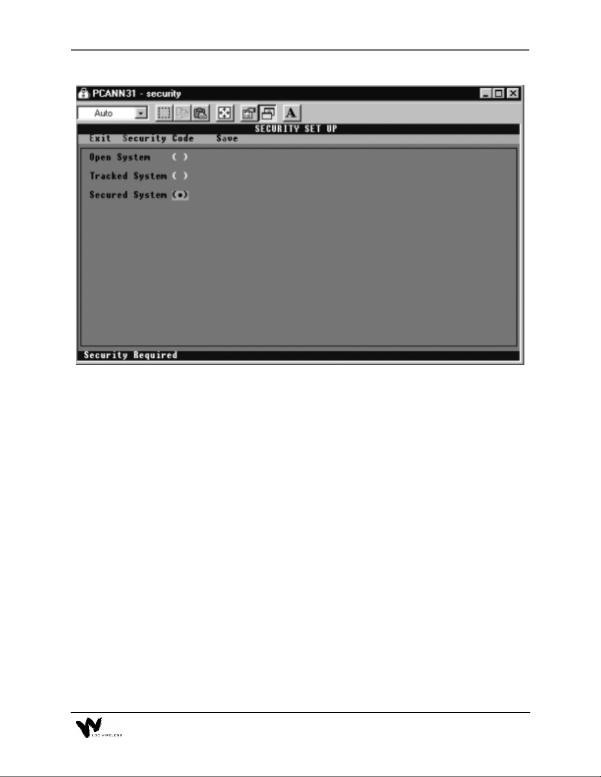
Security Options Screen
Security Options Fields
To select a Security Setup field, use the SPACEBAR key or position the cursor over
the field you want and click the left mouse button. You can set up the security of
the system in one of three ways:
• Open system
In an open system, all functions are availa ble a t all time s. No log-on or lo g-off
procedure is required. This is the least secure system.
• Tracked system
In a tracked system, each user is assigned a security level and an access code.
There are four levels of security, each with progressively more access to the
system. After a user logs on at a given level, all functions for that level are
available to the user.
• Secure system
A secure system functions in the same way as a tracked system, except that level
3 functions (archive and system management) require reentry of the security
code.
E-14 Appendix E – Alarm Report Monitor (ARM2000)
Page 37

Security Codes Screen
The Security Codes screen enables the system supervisor (highest security, Level
3) to change or add operator names and security codes and assign individual
security levels.
Security Code Levels
• Level 0
Allows a user to view status and history screens and to print reports. At this
level, the user will not be able to acknowledge alarms. Any attempt to perform
a function will result in a prompt for a higher security code or log on.
• Level 1
All of Level 0 plus the ability to acknowledge alarms.
• Level 2
All of Level 1 plus the ability to control the remote-ARM relays.
• Level 3
Manager Level. Unrestricted access to all system functions. This level is
required for all setup functions.
E-15
Page 38

Alarm and Device Setup
During the initial test after you complete the setup, PCARM displays the
appropriate clear and alarm conditions. To acknowledge these conditions, click the
ACK button on the Device View screen. During initial setup, all 16 devices are
assumed to be enabled.
Disabling Alarms and Devices
To disable an alarm, place the mouse pointer over the alarm and right click.
PCARM displays a dialog box that asks if you want to be reminded to enable after
an elapsed time. Make your selection of time and press Enter. The alarm is disabled
at this point, both in PCARM and on the REMOTE UNIT display panel.
You can also enable a device in this manner from the System View screen.
Enabling Alarms and Devices
To enable an alarm, place the mouse pointer over the desired alarm and right click.
PCARM displays a dialog box that gives you options to enable or cancel. Click the
enable options, or press E on the keyboard to enable them. (If you attempt to enable
an alarm when appropriate conditions have not been met, the alarm indicator (red
LED) flashes and the PC buzzer sounds.)
You can also enable a device in this manner from the System View screen.
E-16 Appendix E – Alarm Report Monitor (ARM2000)
Page 39

E-17
Page 40

Resetting the Main Hub Remotely
The remote-ARM unit is designed not only to monitor the alarm conditions, but also
to reset the Main Hub from a remote site. When an alarm condition occurs, you can
clear the alarm from the PCARM via the control menu and then reset the Main Hub.
To reset an alarm condition remotely
1
From the Device View screen, click Control Menu to go to the Control Panel
screen.
2
Choose a hub to reset by clicking that hub.
PCARM displays the Control Relay dialog box, which gives you the option to
pulse or change the state of the relay.
3
Click Pulse to reset the hub.
PCARM displays the Pulse Duration dialog box, which asks you for a pulse
time and displays the following message:
ONLY ONE (1) SECOND PULSE IS REQUIRED TO RESET THE HUB.
E-18 Appendix E – Alarm Report Monitor (ARM2000)
Page 41

Choose your time and press Enter
4
If the alarm condition has cleared, the PC buzzer sounds and a status box
appears on your screen.
Click Go To.
5
PCARM displays the Device View screen, on which the cleared alarm(s) flash
green.
To acknowledge the clear condition, click ACK.
6
The flashing green indicator or indicators become solid green.
Control Relay Dialog Box
E-19
Page 42

Pulse Duration Dialog Box
Control Panel Status Box
E-20 Appendix E – Alarm Report Monitor (ARM2000)
Page 43

PCARM Operations
To display, manage, and record alarm monitoring activity in PCARM, you can
perform operations from the System View, Device View, and Alarm View screens.
You can also enable and disable alarms and devices from the System View and
Device View screens.
System View Screen
Overview of the System View Screen
The System View screen displays the current status for all of devices in the entire
system. On the screen, 255 windows display the status for each device in the
system. When no alarms are present, the windows for all of the active devices are
green. If an alarm occurs, the window of the particular device flashes red and the
PC’s buzzer sounds. A status bar at the bottom of the screen displays the current
status of the communications port and operator. At the top of the s creen is a menu
bar for program navigation.
E-21
Page 44

Window Status Indicators
Window State Condition
Green All circuits clear and acknowledged.
Red Alarm condition on one or more channels. All alarms are acknowl-
edged.
Green Flashing Unacknowledged clear event on one or more channels.
Red Flashing Unacknowledged alarm on one or more channels.
Red/Green Flashing Both alarms and clears that are unacknowledged.
Blue Flashing Unit is not responding to polls.
Yellow The device is output only.
Gray Unit is not programmed.
Black Device has been disabled.
Device Selection
To view a particular device, position the cursor over the window of the device and
click the right button. This transfers the program into the device view mode. See
“Device View Screen” on page 25.
Disabling Devices
You can disable devices to allow maintenance of the monitored equipment
without receiving false alarms. To disable a device, position the cursor over the
device and click the right mouse button. PCARM displays a dialog box that
prompts you to enter a reminder time. Enter a desired amount for timer (in
minutes) to be reminded that the device has been disabled, or 0 for no reminder.
Enabling Devices
To enable a device, position the mouse over the desired disabled device and
click the right mouse button. This will cause a confirmation dialog box to be
displayed. To enable the device, click the Enable button on the dialog box or
press the ‘E’ on the keyboard. To cancel, click the Cancel button, press the
‘ESC’ or ‘C’ key on the keyboard.
E-22 Appendix E – Alarm Report Monitor (ARM2000)
Page 45

Status Bar
The status bar is located on the bottom of the System View screen. It displays the
current status of the system. It has three status windows. The function of each of
these windows is described in the following sections:
Communications Port Status
This window is used to display the current status of the communications port. If the
system is configured to be directly connected to a device it will display “Direct
Connect”. If the system is configured to use a modem it displays the current status
of the modem.
Operator Status:
This window is used to display the operator status. In an open system, it displays
“Open System”. In tracked and secured systems, it displays the name of the operator
that is currently logged on or “Please Log On” if no operator is logged on.
System View Menus
The System View menus are located on top of the screen. Descriptions of the menu
choices follow:
•
File
This selection displays a pull down menu with the following choices:
Archive
This selection displays a sub-menu that allows clearing the active Alarm and/or
Control Log and saving the current contents to an Archive file. The data from
the Alarm and/or Control Log are stored in the sub directory archive. These files
are Dbase III compatible. In a tracked or secured system, the user must have a
Level 3 security code.
Exit
This selection terminates the ARM program and returns to DOS.
•
History
This selection displays an Alarm History Screen that lists a full chronological
history of all events (alarms\clears) for the entire system.
E-23
Page 46

•
Setup
This selection displays a pull down menu with the following five choices:
Config ARM
:
This selection accesses the ARM configuration utility.
Device
:
This selection displays a sub-menu that allows access to the device setup
utilities as described below.
REMOTE-ARM
:
This selection accesses the remote-ARM setup utility.
Security
:
This selection accesses the Security Setup utility.
Log On
:
This selection displays the Log On Dialog Box.
Log Off
:
This selection displays the Log Off Dialog Box.
•
Operator Log
This selection displays an Operator History Log that lists a full chronological
history of all operators that have logged into and logged out of the system.
•
Print Current Alarms
This selection generates a report showing all current alarm conditions in the
system.
E-24 Appendix E – Alarm Report Monitor (ARM2000)
Page 47

Device View Screen
Overview of the Device View Screen
The Device View screen displays a Graphic Color Status Display of any individual
front panel with animation of all alarm reporting functions. Each Device View has
the location name of the device printed at the top of the screen (LGC Wireless in
the example above). When no alarms are present all channel LED’s are green, there
is a message ‘ALL CLEAR’, and the time. Each LED has an associated name
(Short Name) printed above it. There is a status bar at the bottom of the screen that
displays the system status. There is a menu bar at the top of the screen for program
navigation.
When an alarm occurs, its associated LED begins to flash red and the PC’s buzzer
sounds until the alarm is acknowledged. Below the front panel, the alarm name,
status, and time/date the alarm occurred is displayed.
When the alarm clears, its associated LED flashes green and the PC’s buzzer
sounds three beeps. When the clear is acknowledged, the channel LED is steady
green.
E-25
Page 48

When you are at the Device View screen, if an event occurs on another device, a
New Event dialog box will pop up over the Device View screen. The New Event
dialog box offers the following choices:
•
Go To
Select to display the device that is alarming.
•
System View
Select to display System View screen.
•
Continue
Select to continue with the device that is presently displayed.
Acknowledging Alarms
Alarms and Clears are both acknowledged in the same manner. Simply position the
cursor over the ACK button and click the left mouse button. If the system has been
configured as an open system and the Require Initials on Acknowledgment option
has been enabled, the Enter Initials dialog box will be displayed. Simply enter your
initials followed by the enter key and the alarm is acknowledged. In tracked and
secured systems, an operator with a security level of one or greater must be logged
on in order to acknowledge and alarm or clear. If no one has logged on prior to
clicking the acknowledge button, the Log on dialog box will be displayed. The ESC
key will cancel the log on procedure without acknowledging the alarm.
Disabling Channels
Individual alarm channels can be disabled to allow equipment maintenance without
causing false alarms. To disable an alarm channel, position the cursor over the
desired disabled channel’s LED and click the right mouse button. A dialog box will
then pop prompting to enter a reminder time. Enter the desired timer (in minutes)
for the disabled reminder to pop up. Enter 0 if no reminder is required.
Enabling Channels
To enable the channel, position the cursor over the desired channe l’s LED and click
the right mouse button. This will cause a confirmation dialog box to be displayed.
To enable the channel, click the Enable button or press the E key. To cancel, click
the Cancel button or press the ESC or C key.
Alarm View Dialog Box
The Alarm View dialog box has been provided as a quick way of viewing the last
two events that occurred on a given channel. To display the Alarm View dialog
box, position the cursor over the desired channel’s LED and click the left mouse
button. This is a non modal dialog box, clicking another channel or anything else
on the screen will close the dialog box and perform the selected function. If the
selected channel has no alarms an error box will be displayed.
E-26 Appendix E – Alarm Report Monitor (ARM2000)
Page 49

Communications Test Function
A communications test function has been provided to test communications between
ARM and the remote-ARM unit and update the status. This should be done after a
new device is installed. To test a device, position the cursor over the test butt on and
click the left mouse button and ARM will call the remote-ARM unit. When the test
is complete a dialog box stating the result of the test will be displayed.
Status Bar
There is a status bar located at the bottom of the screen. This status bar displays the
current status of the system.
Alarm View Screen Overview
The Alarm View Screen provides a quick view of all the alarms (acknowledged and
unacknowledged) in the entire system. The alarms are displayed in chronological
order from the newest to the oldest. The unacknowledged alarms are displayed in
red, and the acknowledged alarms are displayed in blue. Clicking any of the alarms
in this view causes the program to switch to the device view of the selected alarm.
A scroll bar on the right hand side of the screen is provided to scroll through the
alarm list. A menu bar, at the top of the screens, is provided to navigate to other
screens. The contents of this screen can be printed to a printer or file.
E-27
Page 50

Reports
You can display the following reports in PCARM:
• Alarm History Log
• Alarm History by Device
• Alarm Detail
Alarm History Log
The Chronological Alarm History screen displays the entire contents of the Alarm
History Log in chronological order (newest to oldest). A scroll bar on the right hand
side of the screen is provided to scroll through the alarm log. The scroll bar thumb
shows the current position in the file. A menu bar located on the top of the screen
is provided to navigate through the program.
This screen shows the location of the alarm, channel name, and status. For a more
detailed view of an individual alarm, position the cursor over the desired alarm and
click the left mouse button. This causes the Alarm Detail dialog box to be displayed.
In addition to the alarm information, this screen also displays any loss of
communications and restoration of communications.
Alarm History by Device
The Device History screen displays the chronological alarm history (newest to
oldest) of one specific remote-ARM device. A scroll bar on the right hand side of
the screen is provided to scroll through the alarms. The thumb of the scroll bar
shows the position in the file. A menu bar located at the top of the screen is provided
to navigate through the ARM.
This screen shows the channel name, status, and time the event occurred. For a more
detailed view of the event, position the cursor over the desired event and click the
left mouse button and the Alarm Detail Dialog Box will be displayed.
Alarm Detail Dialog Box
The Alarm Detail dialog box is displayed when you click any event in the Alarm
History logs. This dialog box displays the following information for the selected
event:
• Location name
• Channel name
• Status of the channel
• Time the event occurred
E-28 Appendix E – Alarm Report Monitor (ARM2000)
Page 51

• Time the event was acknowledged
• Initials of who acknowledged the event
Operator Log
The Operator Log is a chronological history (newest to oldest) of the operators who
have logged on to the system. This screen contains columns to display the operator
name, time logged on, and the time logged off.
You can access the Operator Log only from the System View screen. Select
Operator Log from the main menu.
Report Printing
PCARM provides the ability to print any of the Alarm, Control, and Operator logs
to either a printer (connected to LPT1) or a file. To print a log, select Print from the
menu of the displayed log. This pops up the following dialog box.
In this dialog box, click the square button next to either LPT1 or FILE. To start
printing, click the OK button. If you select FILE, PCARM displays a second dialog
box in which you can enter the name of the file (up to 13 characters).
When printing begins (to file or printer), PCARM displays the Print Progress dialog
box. You can abort the print job at any time by clicking the Cancel button.
E-29
Page 52

Alarm Logs
To print an alarm log, select the log you want and then select Print from the log
screen’s menu.
Control Logs
To print a control log, display the log and then select Print from the log screen’s
menu.
Current Alarms
ARM provides the ability to print a list of all current alarms (acknowledged and
unacknowledged) to a printer. To print all current alarms, select Print Current
Alarms from the menu on the System View screen.
Operator Log
To print the Operator Log, select Print from the Operator Log menu.
E-30 Appendix E – Alarm Report Monitor (ARM2000)
 Loading...