

Page 1

WaveNet Link CX User Manual
(FCC Certified Version)
Part Number 100757-001
5/02 Version A
Page 2

The products described in this document are products of interWAVE Communications, Inc. or its licensers.
No part of this document may be photocopied, reproduced, translated, transferred, disclosed or otherwise
provided to third parties without the prior written consent of an officer of interWAVE Communications, Inc.
This document applies to the interWAVE Communications, Inc. release of the WaveNet Link product line and
to all subsequent versions and releases of the hardware or software unless otherwise indicated in a new
version or an update package for this edition.
Publications requests should be addressed to your local sales support office.
interWAVE Communications, Inc. reserves the right to make changes to any products described herein at any
time without notice. interWAVE Communications, Inc. does not assume any responsibility or liability arising
out of the application or use of any product described herein, except as expressly agreed to in writing by
interWAVE Communications, Inc. nor does the purchase or use of a product from interWAVE Communications, Inc. convey a license under any patent rights, copyrights, trademark rights, or any other of the
intellectual property rights of interWAVE Communications, Inc. or third parties.
Use, duplication, or disclosure by the U.S. Government is subject to restrictions of FAR 52.227-14 (g) (2)
(6/87) and FAR 52.227-19 (6/87), or DFAR 252.227-7015 (b) (6/95) and DFAR 227.7202-3 (a).
The software described in this document is furnished under a license agreement or nondisclosure
agreement. The software may be used or copied only in accordance with the terms of the agreement. It is a
violation of interWAVE Communications, Inc. proprietary rights to copy the software on any medium except
as specifically allowed in the license or nondisclosure agreement. interWAVE and interWAVE Communications, Ltd. hold the following United States Patents: No. 5,577,029, No. 5,654,968, No. 5,682,403,
No. 5,721,735, No. 5,734,699, No. 5,734,979, No. 5,761,195, No. 5,781,582, No. 5,818,824,
No. 5,842,138, No. 5,887,256, No. 5,953,651, No. 5,957,464, No. 5,999,813, No. 6,070,071,
No. 6,078,823, No. 6,081,716, No. 6,101,400, No. 6,169,907, No. 6,173,177, No. 6,212,395,
No. 6,269,255, No. USP D 391,967, No. USP D 391,968, No. USP D 397,693.
Trademark Acknowledgment
interWAVE, WaveNet, WaveNet Access, WaveNet Link, WaveNet Transport, Broadband Without Boundaries,
StarPort, and StreamNet are trademarks or registered trademarks of interWAVE Communications, Inc. All
other trademarks, service marks and product names mentioned in this document are the property of their
respective owners.
©2002 interWAVE Communications, Inc. All Rights Reserved.
ii
Page 3
United States Federal Communications Commission Required User Documentation
This equipment complies with Part 15 of the FCC Rules. Operation is subject to the following two conditions:
(1) this device may not cause harmful interference, and (2) this device must accept any interference received,
including interference that may cause undesired operation.
Changes or modifications not expressly approved by interWAVE in writing can void the user’s authority to
operate this equipment.
This device must be professionally installed.
This device is to be exclusively used for fixed point-to-point operation
with directional antennas.
iii
Page 4

(this page intentionally left blank)
iv Link CX User Manual, Version A
Page 5

Table of Contents
Welcome! . . . . . . . . . . . . . . . . . . . . . . . . . . . . . . . . . . . . . . . . . . . . . . . . . . . . . . . . . . . . . . . . . . . . . . . . ix
Document Organization . . . . . . . . . . . . . . . . . . . . . . . . . . . . . . . . . . . . . . . . . . . . . . . . . . . . . . . . . . . . . ix
Microwave Radiation Warnings . . . . . . . . . . . . . . . . . . . . . . . . . . . . . . . . . . . . . . . . . . . . . . . . . . . . . . . . ix
Related Documentation . . . . . . . . . . . . . . . . . . . . . . . . . . . . . . . . . . . . . . . . . . . . . . . . . . . . . . . . . . . . .xii
Customer Support Services . . . . . . . . . . . . . . . . . . . . . . . . . . . . . . . . . . . . . . . . . . . . . . . . . . . . . . . . . xiii
Conventions Used in this Manual . . . . . . . . . . . . . . . . . . . . . . . . . . . . . . . . . . . . . . . . . . . . . . . . . . . . . xv
Chapter 1 System Description . . . . . . . . . . . . . . . . . . . . . . . . . . . . . . . . . . . . . . . . . . . . . . . . . . . . . . .1
1-1 General . . . . . . . . . . . . . . . . . . . . . . . . . . . . . . . . . . . . . . . . . . . . . . . . . . . . . . . . . . . . . . . . . . . . . . 1
1-1.1 Products . . . . . . . . . . . . . . . . . . . . . . . . . . . . . . . . . . . . . . . . . . . . . . . . . . . . . . . . . . . . 1
1-1.2 Applications . . . . . . . . . . . . . . . . . . . . . . . . . . . . . . . . . . . . . . . . . . . . . . . . . . . . . . . . . . 2
1-2 System Overview . . . . . . . . . . . . . . . . . . . . . . . . . . . . . . . . . . . . . . . . . . . . . . . . . . . . . . . . . . . . . . 2
1-3 Features . . . . . . . . . . . . . . . . . . . . . . . . . . . . . . . . . . . . . . . . . . . . . . . . . . . . . . . . . . . . . . . . . . . . . 5
1-4 Link CX Basic Structure . . . . . . . . . . . . . . . . . . . . . . . . . . . . . . . . . . . . . . . . . . . . . . . . . . . . . . . . . 6
1-4.1 Radio Links . . . . . . . . . . . . . . . . . . . . . . . . . . . . . . . . . . . . . . . . . . . . . . . . . . . . . . . . . . 6
1-4.2 Data Stream . . . . . . . . . . . . . . . . . . . . . . . . . . . . . . . . . . . . . . . . . . . . . . . . . . . . . . . . . . 6
1-4.3 Link CX Models . . . . . . . . . . . . . . . . . . . . . . . . . . . . . . . . . . . . . . . . . . . . . . . . . . . . . . . 6
1-4.4 Mounting and Antenna Alignment . . . . . . . . . . . . . . . . . . . . . . . . . . . . . . . . . . . . . . . . 7
1-4.5 Interface Connectors and Indicators . . . . . . . . . . . . . . . . . . . . . . . . . . . . . . . . . . . . . . . 7
1-4.6 Cables . . . . . . . . . . . . . . . . . . . . . . . . . . . . . . . . . . . . . . . . . . . . . . . . . . . . . . . . . . . . . . 9
1-4.7 Integral Antenna . . . . . . . . . . . . . . . . . . . . . . . . . . . . . . . . . . . . . . . . . . . . . . . . . . . . . 10
1-4.8 External Antenna . . . . . . . . . . . . . . . . . . . . . . . . . . . . . . . . . . . . . . . . . . . . . . . . . . . . . 11
1-4.9 Configuration, Operation, and Monitoring . . . . . . . . . . . . . . . . . . . . . . . . . . . . . . . . . 13
1-4.10 SNMP . . . . . . . . . . . . . . . . . . . . . . . . . . . . . . . . . . . . . . . . . . . . . . . . . . . . . . . . . . . . 13
1-4.11 Link CX Network Management Architecture . . . . . . . . . . . . . . . . . . . . . . . . . . . . . . . 13
1-4.12 NMS Connectivity . . . . . . . . . . . . . . . . . . . . . . . . . . . . . . . . . . . . . . . . . . . . . . . . . . . 14
1-4.13 Web-Based GUI Access Security . . . . . . . . . . . . . . . . . . . . . . . . . . . . . . . . . . . . . . . . 14
1-4.14 GUI Functions . . . . . . . . . . . . . . . . . . . . . . . . . . . . . . . . . . . . . . . . . . . . . . . . . . . . . . 15
1-5 Typical Applications . . . . . . . . . . . . . . . . . . . . . . . . . . . . . . . . . . . . . . . . . . . . . . . . . . . . . . . . . . . 16
1-5.1 Internet (ISP) . . . . . . . . . . . . . . . . . . . . . . . . . . . . . . . . . . . . . . . . . . . . . . . . . . . . . . . . 17
1-5.2 Private Network Wireless Bridged LANs and WANs . . . . . . . . . . . . . . . . . . . . . . . . . . 17
1-5.3 PCS/PCN and Cellular Networks . . . . . . . . . . . . . . . . . . . . . . . . . . . . . . . . . . . . . . . . . 17
1-5.4 Wireless Local Loop Networks and Local Exchange Bypass . . . . . . . . . . . . . . . . . . . . 17
1-5.5 Business Bypass and Local Exchange Bypass . . . . . . . . . . . . . . . . . . . . . . . . . . . . . . . 17
1-5.6 Backhaul for Wireless MTU and MTU Access . . . . . . . . . . . . . . . . . . . . . . . . . . . . . . . 18
1-5.7 Wireless Mesh Backhaul Networks . . . . . . . . . . . . . . . . . . . . . . . . . . . . . . . . . . . . . . . 19
1-5.8 Wireless ATM Mesh Distribution with StreamNet . . . . . . . . . . . . . . . . . . . . . . . . . . . . 20
1-6 Specifications . . . . . . . . . . . . . . . . . . . . . . . . . . . . . . . . . . . . . . . . . . . . . . . . . . . . . . . . . . . . . . . . 20
Chapter 2 Installation Steering Guide . . . . . . . . . . . . . . . . . . . . . . . . . . . . . . . . . . . . . . . . . . . . . . . . .21
2-1 Installation Flow Chart . . . . . . . . . . . . . . . . . . . . . . . . . . . . . . . . . . . . . . . . . . . . . . . . . . . . . . . . . 21
v
Page 6

Chapter 3 Installation Planning . . . . . . . . . . . . . . . . . . . . . . . . . . . . . . . . . . . . . . . . . . . . . . . . . . . . . .23
3-1 Planning a Link CX Network . . . . . . . . . . . . . . . . . . . . . . . . . . . . . . . . . . . . . . . . . . . . . . . . . . . . . 23
3-2 Site Planning . . . . . . . . . . . . . . . . . . . . . . . . . . . . . . . . . . . . . . . . . . . . . . . . . . . . . . . . . . . . . . . . . 28
3-3 Planning Element and Network Management Ethernet Links . . . . . . . . . . . . . . . . . . . . . . . . . . . . 28
3-4 Planning DS-3 Links . . . . . . . . . . . . . . . . . . . . . . . . . . . . . . . . . . . . . . . . . . . . . . . . . . . . . . . . . . . 30
3-5 Power Planning . . . . . . . . . . . . . . . . . . . . . . . . . . . . . . . . . . . . . . . . . . . . . . . . . . . . . . . . . . . . . . . 30
3-6 Transmit Power Planning . . . . . . . . . . . . . . . . . . . . . . . . . . . . . . . . . . . . . . . . . . . . . . . . . . . . . . . 31
3-6.1 Maximum Link CX Power Output . . . . . . . . . . . . . . . . . . . . . . . . . . . . . . . . . . . . . . . . . 31
3-6.2 Calculating the Required Transmit Power . . . . . . . . . . . . . . . . . . . . . . . . . . . . . . . . . . 31
3-7 Radio Link Planning . . . . . . . . . . . . . . . . . . . . . . . . . . . . . . . . . . . . . . . . . . . . . . . . . . . . . . . . . . . 32
Chapter 4 Installing the Link CX . . . . . . . . . . . . . . . . . . . . . . . . . . . . . . . . . . . . . . . . . . . . . . . . . . . . .35
4-1 Before Installing . . . . . . . . . . . . . . . . . . . . . . . . . . . . . . . . . . . . . . . . . . . . . . . . . . . . . . . . . . . . . . 36
4-1.1 General Guidelines . . . . . . . . . . . . . . . . . . . . . . . . . . . . . . . . . . . . . . . . . . . . . . . . . . .36
4-1.2 Equipment and Unpacking . . . . . . . . . . . . . . . . . . . . . . . . . . . . . . . . . . . . . . . . . . . . . . 37
4-1.3 Packing Lists and Orderable Parts . . . . . . . . . . . . . . . . . . . . . . . . . . . . . . . . . . . . . . . . 37
4-1.4 Installation Tools and Materials . . . . . . . . . . . . . . . . . . . . . . . . . . . . . . . . . . . . . . . . . . 40
4-2 Initial Configuration . . . . . . . . . . . . . . . . . . . . . . . . . . . . . . . . . . . . . . . . . . . . . . . . . . . . . . . . . . . . 41
4-2.1 Connecting a Craft PC to the Link CX . . . . . . . . . . . . . . . . . . . . . . . . . . . . . . . . . . . . . 41
4-2.2 Logging In to the Link CX Built-In Web Server . . . . . . . . . . . . . . . . . . . . . . . . . . . . . . 42
4-3 Mounting the Link CX . . . . . . . . . . . . . . . . . . . . . . . . . . . . . . . . . . . . . . . . . . . . . . . . . . . . . . . . . . 48
4-3.1 Installing the Link CX Mounting Bracket . . . . . . . . . . . . . . . . . . . . . . . . . . . . . . . . . . . 48
4-3.2 Attaching the Link CX to the Mounting Bracket . . . . . . . . . . . . . . . . . . . . . . . . . . . . . . 53
4-4 External Antenna Installation (Optional) . . . . . . . . . . . . . . . . . . . . . . . . . . . . . . . . . . . . . . . . . . . . 56
4-4.1 Installing a Factory-Supplied 4 Foot (122 cm) Antenna Mounting Bracket . . . . . . . . . 56
4-5 Completing the Link CX Installation . . . . . . . . . . . . . . . . . . . . . . . . . . . . . . . . . . . . . . . . . . . . . . . 70
4-5.1 Mounting the Lightning Arrestor . . . . . . . . . . . . . . . . . . . . . . . . . . . . . . . . . . . . . . . . . 70
4-5.2 Routing the Data and Power Cables from the Lightning Arrestor . . . . . . . . . . . . . . . . 70
4-5.3 Grounding the Link CX and Antenna . . . . . . . . . . . . . . . . . . . . . . . . . . . . . . . . . . . . . . 71
4-5.4 Sealing the Data and Power Cable Connectors . . . . . . . . . . . . . . . . . . . . . . . . . . . . . .72
4-6 Aligning the Antenna . . . . . . . . . . . . . . . . . . . . . . . . . . . . . . . . . . . . . . . . . . . . . . . . . . . . . . . . . . 73
4-6.1 Integral Antenna on a Single Adjustable Elevation Mount . . . . . . . . . . . . . . . . . . . . . . 73
4-6.2 Integral Antenna on a Dual Adjustable Elevation Mount . . . . . . . . . . . . . . . . . . . . . . . 74
4-6.3 External Antenna on Antenna-Specific Mount . . . . . . . . . . . . . . . . . . . . . . . . . . . . . . .75
4-7 Acceptance Testing . . . . . . . . . . . . . . . . . . . . . . . . . . . . . . . . . . . . . . . . . . . . . . . . . . . . . . . . . . . 77
Chapter 5 Final Link CX Setup . . . . . . . . . . . . . . . . . . . . . . . . . . . . . . . . . . . . . . . . . . . . . . . . . . . . . . .81
Chapter 6 Monitoring and Trend Analysis . . . . . . . . . . . . . . . . . . . . . . . . . . . . . . . . . . . . . . . . . . . . .83
6-1 Built-In Web Server Interface . . . . . . . . . . . . . . . . . . . . . . . . . . . . . . . . . . . . . . . . . . . . . . . . . . . . 83
6-2 SNMP Network and Element Management Systems . . . . . . . . . . . . . . . . . . . . . . . . . . . . . . . . . . 83
6-2.1 SNMP Details . . . . . . . . . . . . . . . . . . . . . . . . . . . . . . . . . . . . . . . . . . . . . . . . . . . . . . . . 83
6-2.2 Monitoring Error Messages and Traps . . . . . . . . . . . . . . . . . . . . . . . . . . . . . . . . . . . . . 84
Chapter 7 Troubleshooting the Link CX . . . . . . . . . . . . . . . . . . . . . . . . . . . . . . . . . . . . . . . . . . . . . . .85
7-1 Troubleshooting Tables . . . . . . . . . . . . . . . . . . . . . . . . . . . . . . . . . . . . . . . . . . . . . . . . . . . . . . . . 85
vi Link CX User Manual, Version A
Page 7

7-2 Using the Link CX LEDs . . . . . . . . . . . . . . . . . . . . . . . . . . . . . . . . . . . . . . . . . . . . . . . . . . . . . . . . 86
7-3 Using RSSI . . . . . . . . . . . . . . . . . . . . . . . . . . . . . . . . . . . . . . . . . . . . . . . . . . . . . . . . . . . . . . . . . . 86
7-4 Using a Web Browser . . . . . . . . . . . . . . . . . . . . . . . . . . . . . . . . . . . . . . . . . . . . . . . . . . . . . . . . . 86
Appendix 1 Interface Cable Pinouts . . . . . . . . . . . . . . . . . . . . . . . . . . . . . . . . . . . . . . . . . . . . . . . . . . 87
A1-1 DS-3 Cable . . . . . . . . . . . . . . . . . . . . . . . . . . . . . . . . . . . . . . . . . . . . . . . . . . . . . . . . . . . . . . . . 87
A1-2 Ethernet Data Cable . . . . . . . . . . . . . . . . . . . . . . . . . . . . . . . . . . . . . . . . . . . . . . . . . . . . . . . . . 87
A1-3 DC Power Cable . . . . . . . . . . . . . . . . . . . . . . . . . . . . . . . . . . . . . . . . . . . . . . . . . . . . . . . . . . . . 88
A1-4 Ethernet Crossover Cable . . . . . . . . . . . . . . . . . . . . . . . . . . . . . . . . . . . . . . . . . . . . . . . . . . . . . 88
A1-5 External Antenna Cable . . . . . . . . . . . . . . . . . . . . . . . . . . . . . . . . . . . . . . . . . . . . . . . . . . . . . . . 89
A1-6 RS-232 Craft Cable . . . . . . . . . . . . . . . . . . . . . . . . . . . . . . . . . . . . . . . . . . . . . . . . . . . . . . . . . . 89
A1-7 StreamNet ATM Switch Cable . . . . . . . . . . . . . . . . . . . . . . . . . . . . . . . . . . . . . . . . . . . . . . . . . . 90
Appendix 2 Technical Specifications . . . . . . . . . . . . . . . . . . . . . . . . . . . . . . . . . . . . . . . . . . . . . . . . . 91
A2-1 Link CX Radio . . . . . . . . . . . . . . . . . . . . . . . . . . . . . . . . . . . . . . . . . . . . . . . . . . . . . . . . . . . . . . 91
A2-2 Factory-Supplied Antennas . . . . . . . . . . . . . . . . . . . . . . . . . . . . . . . . . . . . . . . . . . . . . . . . . . . . 97
Appendix 3 Using the Web-Based GUI User Interface . . . . . . . . . . . . . . . . . . . . . . . . . . . . . . . . . . . . 99
A3-1 Web Browser Requirements . . . . . . . . . . . . . . . . . . . . . . . . . . . . . . . . . . . . . . . . . . . . . . . . . . . 99
A3-2 Connecting A Web Browser . . . . . . . . . . . . . . . . . . . . . . . . . . . . . . . . . . . . . . . . . . . . . . . . . . . 99
A3-3 Accessing the Link CX Web Pages . . . . . . . . . . . . . . . . . . . . . . . . . . . . . . . . . . . . . . . . . . . . . . 99
A3-4 Link CX Web Pages . . . . . . . . . . . . . . . . . . . . . . . . . . . . . . . . . . . . . . . . . . . . . . . . . . . . . . . . . . 99
Appendix 4 Grounding and Lightning Protection . . . . . . . . . . . . . . . . . . . . . . . . . . . . . . . . . . . . . . . 107
A4-1 Overview . . . . . . . . . . . . . . . . . . . . . . . . . . . . . . . . . . . . . . . . . . . . . . . . . . . . . . . . . . . . . . . . . 107
A4-2 Grounding . . . . . . . . . . . . . . . . . . . . . . . . . . . . . . . . . . . . . . . . . . . . . . . . . . . . . . . . . . . . . . . . 108
A4-3 Lightning Protection . . . . . . . . . . . . . . . . . . . . . . . . . . . . . . . . . . . . . . . . . . . . . . . . . . . . . . . . 109
A4-4 Bibliography . . . . . . . . . . . . . . . . . . . . . . . . . . . . . . . . . . . . . . . . . . . . . . . . . . . . . . . . . . . . . . 110
Appendix 5 Enterprise MIBs and Traps . . . . . . . . . . . . . . . . . . . . . . . . . . . . . . . . . . . . . . . . . . . . . . 111
A5-1 Enterprise MIB . . . . . . . . . . . . . . . . . . . . . . . . . . . . . . . . . . . . . . . . . . . . . . . . . . . . . . . . . . . . 111
A5-2 Enterprise Traps . . . . . . . . . . . . . . . . . . . . . . . . . . . . . . . . . . . . . . . . . . . . . . . . . . . . . . . . . . . 122
Index . . . . . . . . . . . . . . . . . . . . . . . . . . . . . . . . . . . . . . . . . . . . . . . . . . . . . . . . . . . . . . . . . . . . . . . . . 125
vii
Page 8

(this page intentionally left blank)
viii Link CX User Manual, Version A
Page 9

Welcome!
This manual is intended for the technical personnel who will install and operate the U-NII (Unlicensed
National Information Infrastructure) and ISM (Industrial, Scientific and Medical) Link CX. Such personnel
are typically experienced and skilled technicians familiar with on site, physical installation and
connection of equipment, including maintenance work. It is also intended for system administration
personnel performing initial configuration and subsequent system reconfiguration, as well as current
system maintenance activities.
Document Organization
This manual provides a detailed description of the Link CX components, and operating, installation and
management procedures.
• Chapter 1 provides an overview and briefly describes typical applications.
• Chapter 2 provides an installation steering guide with references to subsequent installation
sections.
Preface
• Chapter 3 describes how to plan the Link CX network, radio links, and remote element and
network management links, and individual Link CX radios.
• Chapter 4 provides detailed hardware installation and acceptance test procedures.
• Chapter 5 describes final configuration procedures and the Web browser user interface.
• Chapter 6 presents procedures for monitoring and performing trend analysis on the
Link CX.
• Chapter 7 provides instructions for troubleshooting the Link CX.
• Appendixes provide detailed technical information for carrying out the installation and main-
tenance activities described in the other chapters of this manual.
Microwave Radiation Warnings
Radio Warning
Under normal operating conditions, Link CX radio equipment complies with the limits for human
exposure to radio frequency (RF) fields adopted by the Federal Communications Commission (FCC). All
interWAVE Communications, Inc. microwave radio equipment is designed so that under normal working
conditions, microwave radiation directly from the radio is negligible when compared with the
permissible limit of continuous daily exposure recommended in the United States by ANSI/IEEE
C95.1-1991 (R1997), Safety Levels with Respect to Human Exposure to Radio Frequency Electromagnetic Fields, 3 kHz to 300 GHz.
ix
Page 10
Microwave signal levels that give rise to hazardous radiation levels can exist within transmitter power
amplifiers, associated RF multiplexers, and antenna systems.
Antenna Warning
Designed for point-to-point operation, the Link CX microwave radio system uses directional antennas to
transmit and receive microwave signals. These directional antennas are usually circular or rectangular,
are generally located outdoors, and are usually mounted with the Link CX on a tower or mast.
The Link CX is classified as a fixed installation product, and per FCC policy guidelines regarding
maximum permissible exposure (MPE), antennas used for this interWAVE radio must be installed to
provide a separation distance of 2 m (79 in.) or more from all persons during normal operation to satisfy
FCC RF exposure limits. As the Link CX is typically mounted on a building or mast high enough to clear
ground-level path obstructions, the general population will be further than 2 m (79 in.) from the radio
antenna, and the FCC RF exposure limits will be met.
interWAVE Communications, Inc. fully supports the FCC’s adopted MPE limits, and recommends that
personnel stay 2 m (79 in.) or more from the front of all directional microwave antennas. Should you
have questions about Link CX microwave signal radiation, please contact interWAVE Customer Support.
Never look into the front of an open RF connection or RF antenna as eyes
are particularly vulnerable to radiation. Do not disconnect RF coaxial
connectors, open microwave units, or break down any microwave
screening while the radio equipment is operating.
FCC Regulatory Information
The Link CX is certified for use in the 5.3 GHz and 5.8 GHz unlicensed bands in the United States.
The 5.3 GHz version of the Link CX is certified under FCC part 15.407, U-NII regulations covering the
frequency band of 5250-5350 MHz.
5.3 GHz (5.25-5.35 GHz)
5.3 GHz Link CX radios are equipped with an integral antenna only, and operate under the FCC Part 15,
subpart E, U-NII license-exempt regulations, which certify the radios for –1.0 dBm average, or
+7.4 dBm peak transmit power. The 5.3 GHz Link CX radios have been certified in the following
configuration:
• Link CX, 5.3 GHz, integral antenna
The following table summarizes the technical specifications of the 5.3 GHz version of the Link CX.
x Link CX User Manual, Version A
Page 11

Table 1 5.3 GHz Link CX Specifications
Parameter Description
FCC Identifier OEWCX-DS3-53G
Frequency Band 5250 – 5350 MHz, U-NII per 15.407
Mode of Operation Full Duplex, 100% duty cycle
Channel Spacing 16 MHz
Transmit / Receive Separation 60 MHz
Number of Channel Pairs 2
Channel Pair 1 5262 MHz / 5322 MHz
Channel Pair 2 5278 MHz / 5338 MHz
Modulation 16 QAM, α = 0.15
Emission Bandwidth (26 dB) 13.9 MHz
Frequency Stability +/- 5.0 PPM
Maximum Output Power -1.0 dBm average (+7.4 dBm peak)
Antenna Type Integral flat panel
Antenna Gain 21 dBi
User Interfaces
5.8 GHz (5.725-5.825 GHz)
The 5.8 GHz Link CX radios operate under the FCC Part 15.247 band regulations, which certify the
radios for +16 dBm average or +24.1 dBm peak transmit power for intentional radiators in a
point-to-point configuration. The 5.8 GHz Link CX radios are equipped with an integral or an external
antenna. The 5.8 GHz Link CX radios have been FCC certified in the following configurations:
• Link CX, 5.8 GHz, integral antenna
• Link CX, 5.8 GHz, 2 ft. (61 cm) external Radio Waves, Inc. Model SP2-5.2 parabolic antenna
• Link CX, 5.8 GHz, 2 ft. (61 cm) external Gabriel Electronics, Inc. Model SSP2-52B parabolic
antenna
• Link CX, 5.8 GHz, 4 ft. (122 cm) external Gabriel Electronics, Inc. Model SSP4-52B para-
bolic antenna
See the following table summarizing the technical specifications for the 5.8 GHz version of the Link CX.
DSX3 coaxial, 10/100 base-T Ethernet, Craft PC RS-232
interface
xi
Page 12

Table 2 5.8 GHz Link CX Specifications
Parameter Description
FCC Identifier OEWCX-DS3-58G
Frequency Band 5725 – 5850 MHz, per 15.247, revised 5/16/02
Mode of Operation Full Duplex, 100% duty cycle
Channel Spacing 16 MHz
Transmit / Receive Separation 60 MHz
Number of Channel Pairs 2
Channel Pair 1 5737 MHz / 5797 MHz
Channel Pair 2 5753 MHz / 5813 MHz
Modulation 16 QAM, α = 0.15
Emission Bandwidth (26 dB) 13.9 MHz
Frequency Stability +/- 5.0 PPM
Maximum Output Power +16 dBm average (+24.1 dBm peak)
Integral flat panel, 2 ft. parabolic – Radio Waves, Inc.
Antenna Types
Model SP2-5.2, 2 ft. parabolic – Gabriel Electronics, Inc.
Model SSP2-52B
4 ft. parabolic – Gabriel Electronics, Inc. Model SSP4-52B
Antenna Gains 21 dBi, 28.3 dBi, and 34.6 dBi
User Interfaces
Note that any references in this manual referring to external antennas, or external antenna mounting
only apply to the 5.8 GHz version of the Link CX. The 5.3The 5.8 GHz Link CX radios are equipped with
an integral or an external antenna, GHz version is certified for use with the integral antenna only.
Related Documentation
All interWAVE manuals are available in an online format on our protected Internet site. To order documentation, please contact interWAVE Communications, Inc. Sales department online at
http://www.iwv.com.
Updates to this manual will be posted on the interWAVE Communications, Inc. Customer Support
website at http://www.iwv.com/custsupport. Registered interWAVE customers can access the
interWAVE online information and support service, available 24 hours a day, seven days a week. The
interWAVE online service provides users with a wealth of up-to-date information, with documents being
added or updated each month.
DSX-3 coaxial, 10/100 base-T Ethernet, Craft PC RS-232
interface
xii Link CX User Manual, Version A
Page 13

Customer Support Services
interWAVE has regional Customer Support centers that handle day-to-day customer issues. Each center
is staffed with a local technical support group. The exact services to be performed by the interWAVE
Customer Support department are specified in a support contract. Below is an example of the types of
services available:
• Telephone support
• Site surveys
• Installations
• Off-line and online commissioning
• Network integration activities
• Troubleshooting and fault isolation
• Escalation of problems to appropriate interWAVE technical departments
interWAVE can physically perform all or a portion of these processes for the operator, as specified in
the support contract. The Customer Support department can also provide documentation outlining
corrective and preventive maintenance procedures and troubleshooting guides for fault isolation.
Contact your local Sales Support office
http://www.iwv.com.
If possible, please have the following information available when making a call:
• Site number or name
• Full description of product(s) (e.g., model and part number) and configuration
• Serial number of product(s)
• Purchase order number
• Contact name and telephone number
• Ship to address
• Bill to address
For support on installing or configuring all interWAVE equipment, contact your Regional interWAVE
Customer Support Center at:
• +852.2574.1922 or asia_support@iwv.com.hk -- Asia and Pacific Rim
• +1.866.306.1263 or usa_support@iwv.com -- North and South America, Europe, Africa,
and Middle East
or via the Internet at http://www.iwv.com/custsupport.
, or interWAVE headquarters directly via the Internet at
xiii
Page 14

Return Materials Authorization
In the event that a depot repair or hardware replacement is required after contacting Customer Support,
please contact interWAVE for return authorization. The following information is required by interWAVE:
• Full description of the product(s): model and part number
• Serial number of the product(s)
• Purchase order number
• Quantity that needs to be returned to interWAVE, if applicable
• Description of observed problem
All interWAVE products carry a one year manufacturing warranty from the date of shipment. At the time
of a request for a return authorization, if the product has exceeded the warranty period, interWAVE will
require a new purchase order number to cover the cost of non-warranty repair.
Contact Sales Operations via the Internet at http://www.iwv.com or email at rma@iwv.com.
Traini ng
interWAVE has developed an extensive series of training courses designed to teach you how to use our
products. The courses are developed by a combination of subject matter experts and training specialists
in order to create highly technical materials in modern training format. Each of our course offerings are
designed around specific learning objectives that keep our classes on track to learning specific job skills
related to interWAVE products.
The interWAVE training catalog contains a listing of the interWAVE training services available along with
descriptions of each course. Our training materials are divided into specific subsystem training series,
depending upon the topic and job requirements.
Contact Customer Support via the Internet at http://www.iwv.com or email at training@iwv.com.
xiv Link CX User Manual, Version A
Page 15
Conventions Used in this Manual
The following type and style conventions are used in this manual:
sssssssssssss ssssssssssssss sssssssssssss ssssssssssssss sssssssssssss sssssssssssssss ssssssssssss sssssssssssssss ssssssssssss sssssssssssss ssssssssssss sssssssssssssss ssssssssssss sssssssssssssss ssssssssssss sssssssssssssss ssssssssssss sssssssssssssss ssssssssssss sssssssssssssss sssssssssssssss ssssssssssss sssssssssssssss ssssssssssss sssssssssssssss ssssssssssss sssssssssssssss ssssssssssss sssssssssssssss ssssssssssss sssssssssssssss sssssssssssss ssssssssssssss sssssssssssss ssssssssssssss sssssssssssss ssssssssssssss sssssssssssss ssssssssssssss sssssssssssss ssssssssssssss sssssssssssssss ssssssssssss sssssssssssssss sssss
sssssssssssss ssssssssssssss sssssssssssss ssssssssssssss sssssssssssss sssssssssssssss ssssssssssss sssssssssssssss ssssssssssss sssssssssssss ssssssssssss sssssssssssssss ssssssssssss sssssssssssssss ssssssssssss sssssssssssssss ssssssssssss sssssssssssssss ssssssssssss sssssssssssssss sssssssssssssss ssssssssssss sssssssssssssss ssssssssssss sssssssssssssss ssssssssssss sssssssssssssss ssssssssssss sssssssssssssss ssssssssssss sssssssssssssss sssssssssssss ssssssssssssss sssssssssssss ssssssssssssss sssssssssssss ssssssssssssss sssssssssssss ssssssssssssss sssssssssssss ssssssssssssss sssssssssssssss ssssssssssss sssssssssssssss sssss
sssssssssssss ssssssssssssss sssssssssssss ssssssssssssss sssssssssssss sssssssssssssss ssssssssssss sssssssssssssss ssssssssssss sssssssssssss ssssssssssss sssssssssssssss ssssssssssss sssssssssssssss ssssssssssss sssssssssssssss ssssssssssss sssssssssssssss ssssssssssss sssssssssssssss sssssssssssssss ssssssssssss sssssssssssssss ssssssssssss sssssssssssssss ssssssssssss sssssssssssssss ssssssssssss sssssssssssssss ssssssssssss sssssssssssssss sssssssssssss ssssssssssssss sssssssssssss ssssssssssssss sssssssssssss ssssssssssssss sssssssssssss ssssssssssssss sssssssssssss ssssssssssssss sssssssssssssss ssssssssssss sssssssssssssss sssss
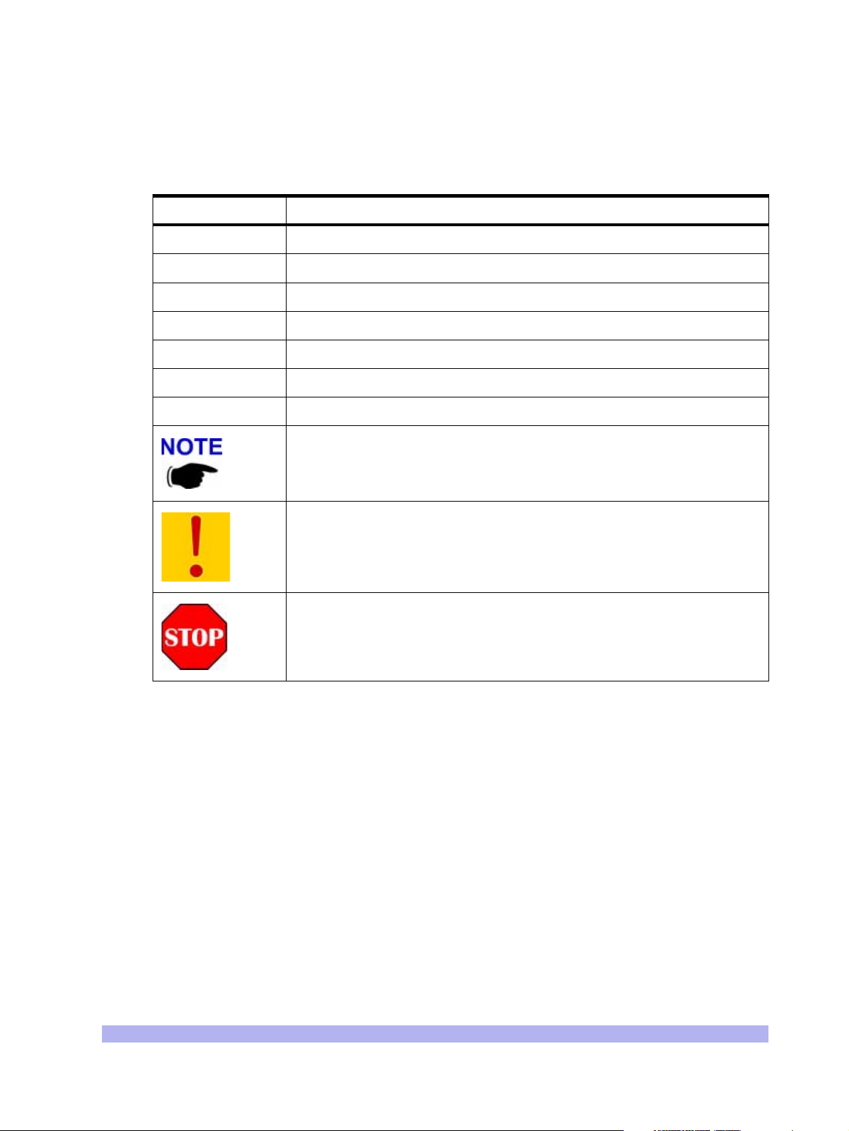
Table 3 Conventions Used in This Manual
Convention Meaning
sssssssssssss ssssssssssssss sssssssssssss sssssssssssssss ssssssssssss sssssssssssssss ssssssssssss sssssssssssssss ssssssssssss sssssssssssss ssssssssssss sssssssssssssss ssssssssssss sssssssssssssss ssssssssssss sssssssssssssss ssssssssssss sssssssssssssss sssssssssssss ssssssssssssss sssssssssssssss ssssssssssss sssssssssssssss sssssssssss
Body text
Bold
Used for regular body text
Indicates a menu or button choice
Command Indicates computer generated text and prompts
User Input Indicates user input
<hostname> In command syntax, indicates user-specified command line parameters
<variable> In body text, indicates user-specified command line parameters
[BRACKETS] Indicates a key on the keyboard or instrument
Provides relevant additional information
Provides important warning information that may affect operation of or
maybe a potential threat to the system
Used to tell the reader to
STOP what they are doing and to read
important instructions that are vital to prevent equipment or software
damage
xv
Page 16

(this page intentionally left blank)
xvi Link CX User Manual, Version A
Page 17

One
System Description
10000
This chapter contains a functional description of the Link CX product family, and contains the following
sections:
• Section 1-1, General
• Section 1-2, System Overview
• Section 1-3, Features
• Section 1-4, Link CX Basic Structure
• Section 1-5, Typical Applications
Welcome to the interWAVE WaveNet Link Series product family. This manual is designed to introduce
you to the Link CX products, and to provide you with information necessary to plan, install, operate and
maintain a Link CX wireless communication system.
The Link CX is intended for professional installation only. However, this manual is also designed for
personnel who plan, operate and administer the Link CX communication system. Please review the
entire manual before powering up or deploying any Link CX.
1-1 General
1-1.1 Products
The Link CX products are cost-effective, all-outdoor, pole-mounted, high-capacity, line-of-sight (LOS)
digital radio transmission systems, each operating in the license-exempt 5.25-5.35 GHz (5.3 GHz) or
5.725-5.825 GHz (5.8 GHz) frequency bands. The Link CX can be used for the following applications:
point-to-point or building-to-building, WLL (wireless local loop), backup solutions, temporary links, and
mesh cellular backhaul.
• The 5.3 GHz Link CX-DSX DS-3 and 10/100 versions conform to the FCC (Federal Commu-
• The 5.8 GHz Link CX-DSX DS-3 and 10/100 versions conform to the FCC Part 15.247
Both Link CX-DSX versions provide either a standard DS-3 (44.736 Mbps) interface adhering to
Bellcore GR-499-CORE (DSX-3) standards, or provides two Ethernet 10/100Base-T interfaces adhering
to IEEE 802.3 standards, with a combined nominal line rate of 45 Mbps.
nications Commission) Part 15.407 Subpart E describing U-NII (Unlicensed National
Information Infrastructure) operation. It operates at up to -1.0 dBm average transmit power,
and is intended for short-distance use.
describing intentional radiators. It operates at up to +16 dBm average power, and is
intended for use over longer distances.
System Description 1
Page 18

Each Link CX is powered by an external ±21 to ±60 VDC power supply.
1-1.2 Applications
The Link CX product line is designed to serve the following communications markets:
• Internet Access and Backhaul Systems: Used by Internet Service Providers (ISPs).
• Private Networks: Wireless Bridged LANs and WANs.
• PCS/PCN and Cellular Networks: High speed links between base stations.
• Wireless Local Loop Networks: Fixed wireless, used by Local Exchange Carriers (LECs).
• Business Bypass or Local Exchange Bypass: Provided by Competitive Access Providers
(CAPs) and Competitive Local Exchange Carriers (CLECs).
• When used with interWAVE StreamNet ATM Switches, the Link CX can provide the radio
links in a self-healing wireless mesh backhaul network to support broadband communications, including DSL (Digital Subscriber Line) and Cellular over ATM (Asynchronous Transfer
Mode).
1-2 System Overview
Each Link CX consists of a Link CX radio, with integral antenna (5.3 GHz or 5.8 GHz versions) or an
optional external antenna (5.8 GHz versions), as shown in Figure 1-1, along with external power and
data cabling. In a typical installation, the Link CX radio and antenna are mounted outdoors, usually on a
tower or building. If so equipped, the external antenna connects to the Link CX radio through a
factory-supplied coaxial cable.
See Figure 1-1. A radio system, or link, contains two Link CX radios each equipped with either an
integral or external antenna, installed at each end of the link, separated by a line of sight transmission
path. Frequency band, terrain, actual line-of-sight and environmental conditions influence the range of
operation and path performance.
The Link CX carries one full-duplex DS-3 or Ethernet channel, and is powered by a 30-watt external
±21 to ±60 VDC power supply.
2 Link CX User Manual, Version A
Page 19
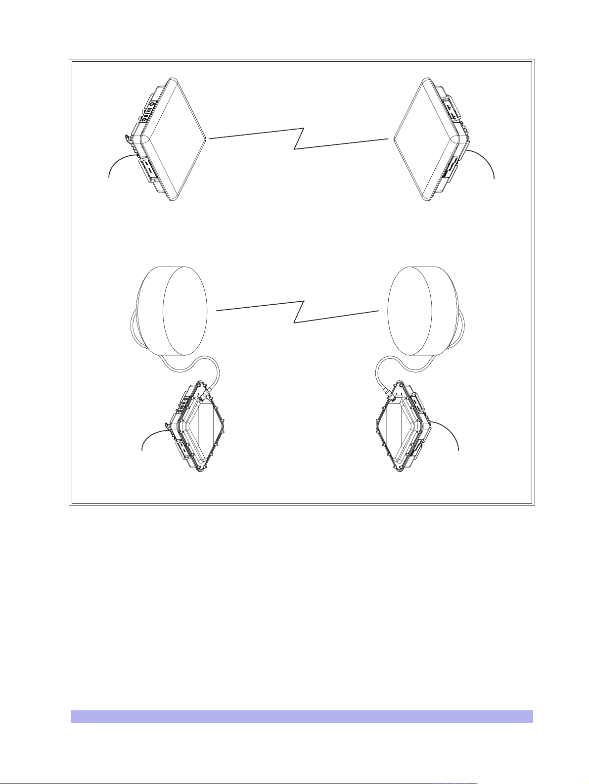
Line of Sight
Transmission Path
DS-3 or
Ethernet Data
A. Radio Link using 5.3 GHz or 5.8 GHz Link CX with Integral Antennas
DS-3 or
Ethernet Data
Line of Sight
Transmission Path
Ethernet Data
B. Radio Link using 5.8 GHz Link CX with External Antennas
DS-3 or
DS-3 or
Ethernet Data
IW140201
Figure 1-1 Typical Radio Link Configurations
System Description 3
Page 20
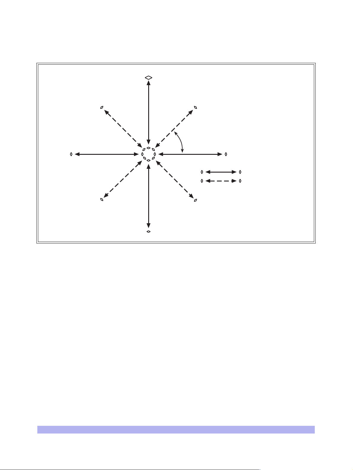
Because the Link CX can be ordered in two different bands, with high and low channels, and can be
installed with horizontal or vertical polarization, up to eight Link CXs can be mounted at a each hub, or
node, to form part of a star or mesh network. See Figure 1-2.
1H 5.8
2H 5.31V 5.3
a
2V 5.8
2H 5.31V 5.3
1H 5.8
Figure 1-2 CX-UNII and CX-ISM Star Network
2V 5.8
a =
1H =
2V =
Link CX 5.8
Link CX 5.3
0 - 90°
Channel 1,
Horizontal
Channel 2,
Vertical
IW134204
4 Link CX User Manual, Version A
Page 21

1-3 Features
The Link CX offers the following features:
• Robust outdoor all-outdoor enclosure.
• Integral or external antenna.
• Sturdy radio mounting systems for quick, accurate and reliable integral antenna alignment.
• Operates in the license-exempt 5.25-5.35 GHz (5.3 GHz) or 5.725-5.825 GHz (5.8 GHz)
• Conforms with FCC Part 15.247 rules (5.725-5.825 GHz) or Part 15.407 rules
• Full-duplex transmission:
• Easy configuration, installation, operation, and maintenance.
• Integral web server for configuring, operating, and monitoring using an HTML-based web
• Ethernet interface used with NMSs (Network Management Systems) or EMSs (Element
bands.
(5.25-5.35 GHz).
• DS-3 (DSX-3, per Bellcore GR-499-CORE)
• Ethernet 10/100Base-T (per IEEE 802.3)
browser GUI.
Management Systems) using SNMP (Simple Network Management Protocol) traps. Supports
MIB-II (Management Information Base II) and interWAVE enterprise MIB.
• ATPC (Automatic Transmit Power Control).
• Self Test, BER test mode, RF and digital loopbacks.
• Reed Salomon Forward Error Correction (FEC).
• Operating and backup software versions contained in Link CX memory, operator-selectable.
System Description 5
Page 22

1-4 Link CX Basic Structure
1-4.1 Radio Links
Each radio link includes two Link CX terminals. Each terminal consists of a Link CX radio with an integral
flat-panel antenna, or a Link CX radio with an external antenna (see Figure 1-1). Generally, the Link CX
terminals are mounted outdoors on a tower or building.
1-4.2 Data Stream
The DS-3 or Ethernet data signals enter the Link CX, and are modulated into the RF data stream. The RF
radio signal radiates from the local antenna and propagates to the remote antenna. At the remote
terminal, the received signal is demodulated and demultiplexed, separating the payload data and the
overhead management data.
1-4.3 Link CX Models
The Link CX is manufactured in many configurations:
• Versions with DS-3 or Ethernet carried over 5.3 GHz or 5.8 GHz links.
• Each version available with either an integral 30 x 30 cm (12 x 12 in.) antenna, or with an
N-type connector for a factory-supplied 61 cm (2 ft.) or 122 cm (4 ft.) external antenna, or
an N-type connector for a customer-supplied external antenna.
Link CX models are described in Table 1-1.
Table 1-1 Link CX Models
Model
M100746-101
M100747-101
M100748-101
M100749-101
M100748-102
M100749-102
M100746-201
M100747-201
M100748-201
M100749-201
M100748-202
M100749-202
Transm i
t Band
Low
High
Low
High
Low
High
Low
High
Low
High
Low
High
Frequency Band Link Carries Antenna
5.25-5.35 GHz DS-3 Integral
5.725-5.825 GHz DS-3 Integral
5.725-5.825 GHz DS-3 External, 61 or 122 cm (2 or 4 ft.)
5.25-5.35 GHz
5.725-5.825 GHz
5.725-5.825 GHz
Ethernet
(45 Mbps)
Ethernet
(45 Mbps)
Ethernet
(45 Mbps)
Integral
Integral
External, 61 or 122 cm (2 or 4 ft.)
6 Link CX User Manual, Version A
Page 23
1-4.4 Mounting and Antenna Alignment
To ensure proper mounting and antenna alignment interWAVE sells mounting brackets designed for use
with the Link CX. The single bracket mounts one Link CX, while the dual bracket mounts two Link CXs
back-to-back. Both brackets are designed to provide rugged mounting for the Link CX, while allowing
fine adjustment for antenna alignment.
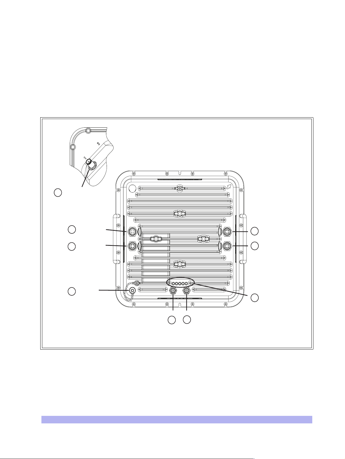
1-4.5 Interface Connectors and Indicators
See Figure 1-3 for a view of the Link CX external connectors and indicators. The Link CX connectors
and indicators are described in Table 1-2.
8 External Antenna
(on far side,
if equipped)
1 POWER
2 CRAFT
3 RSSI
4 OUT
5 IN
Figure 1-3 Link CX Interface Connectors and Indicators
7 ETHERNET 1
6 ETHERNET 2
9 LEDs
IW060203
System Description 7
Page 24

Table 1-2 Link CX Interface Connectors and Indicators
No. Name Component Description From Note
1POWER
2 CRAFT
3 RSSI
4OUT
5IN
6 ETHERNET 2
7 ETHERNET 1
Male 4-Pin
Circular
Connector
Female 4-Pin
Circular
Connector
Female BNC
Connector
Female TNC
Connector
Female TNC
Connector
Female 4-Pin
Circular
Connector
Female 4-Pin
Circular
Connector
Power input plug Power Supply
RS-232
receptacle
Receive Signal
Level Indicator
DS-3 data from
the radio link
DS-3 data to the
radio link
10/100Base-T
transmit and
receive
receptacle
10/100Base-T
transmit and
receive
receptacle
Asynchronous
laptop port
Voltmeter
DS-3 data
equipment
DS-3 data
equipment
Ethernet
equipment
Ethernet
equipment
Accepts ±21 to
±60 VDC
1200 to 115,200 baud,
used only for tech
support troubleshooting
Verifies RF signal
strength, used to align
antenna
--
--
For Ethernet data or link
to SNMP or Web
manager, or use to
daisy-chain Ethernet
port to next Link CX in
cascade
(Same as ETHERNET 2)
8
9
ANTENNA
PORT (Opt.)
PWR/LCL ALM
RF LINK
DATA
ENET 2
ENET 1
Female
N-type
Connector
Green LED
Green LED
Green LED
Green LED
Green LED
50 Ohm RF
receptacle
Power/Local
Alarm Status
Radio Link Status
DS-3 Status
Ethernet Status
Ethernet Status
External
antenna
--
Only equipped on
external-antenna
models, on far side of
chassis
ON = Power OK, no
alarm, Flashing = Local
alarm, OFF = Power off.
ON = Rcv. OK,
OFF = Link Alarm.
ON = OK (no LOS),
OFF = LOS.
ON = OK, Flashing =
data, OFF = No conn.
ON = OK, Flashing =
data, OFF = No conn.
Note: For connector pinouts, refer to Appendix 1.
8 Link CX User Manual, Version A
Page 25
1-4.6 Cables
To ensure longevity in a outdoor environment, interWAVE sells various cables designed for use with the
Link CX. interWAVE offers the following weather-resistant cables:
• DS-3 and Ethernet data cables and the power cables are offered in 25 m (82 ft.), 50 m
(164 ft.), and 100 m (328 ft.) lengths.
• A 6 m (19.7 ft.) Ethernet cable is available to route the Ethernet signal between two Link CXs
in the same location, or when you are configuring the Link CX from a Craft PC.
• For models to be used with external antennas, a 2 m (6.6 ft.) N-to-N RF cable is available to
connect the external antenna to the Link CX.
• A 6 m (19.7 ft.) RS-232 4-pin Circular-to-DB9 Craft cable is available to connect a Craft PC
to a Link CX for future CLI applications.
• When the Link CX is to be used with a StreamNet ATM Switch for a mesh backhaul network,
a 6 m (19.7 ft.) dual TNC-to-TNC cable is available to connect each StreamNet ATM Switch
to a Link CX.
All of the cables described above include weather-resistant connectors
and moisture-excluding gel inside the cable sheaths. For this reason,
interWAVE recommends that customers and installers not attempt to
shorten or splice the factory-supplied cables.
System Description 9
Page 26
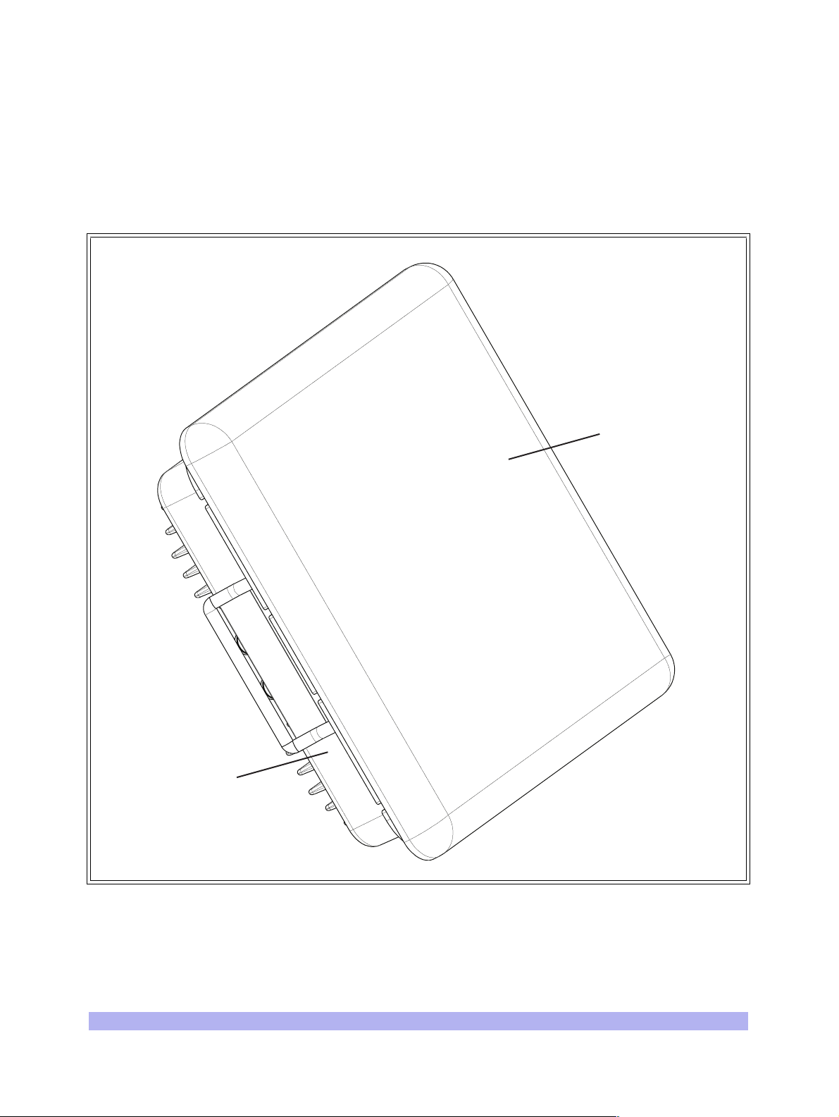
1-4.7 Integral Antenna
The integral antenna is a 30 cm x 30 cm (12 in. x 12 in.) flat-panel antenna mounted directly on the
5.3 GHz or 5.8 GHz Link CX radio chassis, as shown in Figure 1-4. All RF connections between the
integral antenna and the Link CX radio are made internally, eliminating the need for external coaxial
cabling. Because the integral antenna is sealed onto the Link CX chassis, the Link CX and integral
antenna are mounted as a unit, and share the same environmental protection. An arrow on the
connector side of the Link CX chassis indicates the antenna polarization (either vertical or horizontal).
Integral
Antenna
Link CX
Radio
IW060201
Figure 1-4 Integral Antenna and Link CX Radio
10 Link CX User Manual, Version A
Page 27

1-4.8 External Antenna
Some 5.8 GHz Link CX models use an external antenna to radiate and receive RF signals. The antenna
attaches to the Link CX via a factory-supplied cable. The following sections describe factory- and
customer-supplied external antennas.
Factory-Supplied
The following external antennas are offered for use with the Link CX:
• 61 cm (2 ft.) parabolic type
• 122 cm (4 ft.) parabolic type
Figure 1-5 shows a typical 61 cm external antenna with N-type connector cabled to the Link CX radio.
The antenna type should be selected according to local regulatory rules and system gain requirements.
For the available antenna models refer to Table 1-3. Complete antenna specifications are provided in
Appendix 2.
Table 1-3 Antenna Models
Model Description
091-455524-101 Parabolic antenna, 5.725-5.825 GHz, 61 cm (2 feet)
091-455548-101 Parabolic antenna, 5.725-5.825 GHz, 122 cm (4 feet)
Customer-Supplied
The Link CX can be ordered with a coaxial cable to be connected to a customer-supplied external
antenna. In this case, refer to the external antenna user documentation for specifications and model
numbers.
System Description 11
Page 28
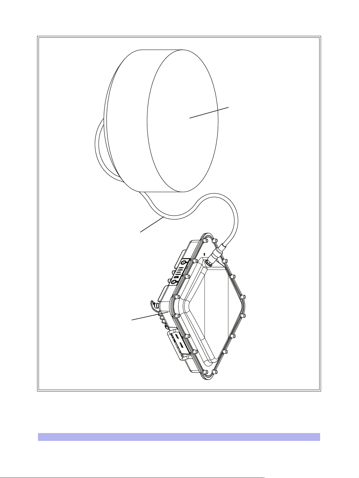
FactorySupplied
Coaxial Cable
External
Antenna
Link CX
Radio
IW060204
Figure 1-5 Typical Factory-Supplied External Antenna and 5.8 GHz Link CX Radio
12 Link CX User Manual, Version A
Page 29
1-4.9 Configuration, Operation, and Monitoring
The Link CX and radio link are configured, operated and monitored through one of five user interfaces.
The five interfaces are:
• A built-in web server GUI hosted by the Link CX, which can be accessed by any local or
remote computer equipped with a web browser. This is the interface most operators will use
to interact with the Link CX. The web browser can access the Link CX built-in web server
through either the ETHERNET 1 or ETHERNET 2 port.
Note that the ETHERNET 1 and ETHERNET 2 ports are functionally
equivalent, and that they are both served by an onboard Ethernet
controller. The controller automatically switches polarity on the transmit
and receive pairs when they are reversed, eliminating the need for
crossover cables.
• SNMP traps, which communicate with MIB-II compliant NMSs (Network Management
Systems) and EMSs (Element Management Systems). This interface is used by operators
who want real-time notification of radio problems. The Link CX sends SNMP traps to NMSs
and EMSs over Ethernet links through either the ETHERNET 1 or ETHERNET 2 port.
• An ASCII command line interface, accessible through the RS-232 CRAFT port, or through
the ETHERNET 1 or ETHERNET 2 port using telnet. This interface is primarily used by operators and interWAVE technical support personnel when performing detailed troubleshooting.
• The RSSI port, providing a DC voltage level proportionate to the received RF signal level, and
allowing installers to use a DC voltmeter to fine-tune antenna alignment. This interface is
primarily used during installation, but the current RSSI measurement is also available via the
Link CX built-in web server or via SNMP polls.
• Five LEDs that provide visual alarm status. They verify proper operation of the Ethernet
ports, DS-3 ports, and radio link, and indicate proper power input and radio operation.
These LEDs are usually used during installation to provide a quick product verification.
1-4.10 SNMP
The Link CX radio supports SNMP network management. SNMP is a protocol that defines the method of
communicating with and controlling network devices.
Devices that support the SNMP protocol can be queried for their status and other device information.
Some devices allow changing device settings or configurations using SNMP commands. The device
settings and other device data are available as variables. They are defined in the standard Management
Information Base (MIB) file, provided by the device manufacturer. The SNMP manager uses a database
to hold lists of variables that can be accessed for each device on the network. The device data can be
displayed in tables, graphs, or saved in a file.
1-4.11 Link CX Network Management Architecture
Link CX software network management is comprised of two main items:
• SNMP based Network Management System (NMS) application in the network management
workstation.
System Description 13
Page 30

Polling
Traps
• SNMP agent in the Link CX.
The workstation manages all Link CXs assigned unique IP addresses. The workstation also provides a
graphical display of the network objects showing the status, performance, and configuration parameters
of each Link CX radio.
The SNMP local agent is a standard MIB-II compliant software module that resides in each Link CX. The
agent collects information from different Link CX components as defined in the Management
Information Base (MIB) structure. The Link CX incorporates both standard and private MIBs.
Different Link CXs are distinguished by their customer-assigned IP addresses. The Web browser
communicates with the Link CX using TCP/IP and HTTP protocol.
The NMS data transfer between the manager and the agents is accomplished using either polling or
trapping techniques.
The NMS polls each Link CX SNMP agent at specific intervals. These are set according to user
requirements during SNMP NMS configuration.
The Link CX agent sends an SNMP trap to the manager whenever a predefined event occurs. Groups of
traps can be defined according to their level of severity. The operator can choose to enable or disable
any traps or group of traps according to their level of severity (and his or her own security level). Traps
can be logged using any standard SNMP manager.
1-4.12 NMS Connectivity
The NMS workstation can access any Link CX using its IP address. The NMS workstation can connect to
each Link CX using any of the following methods:
• 10/100 Base-T Ethernet - accessing Link CXs via a LAN through hubs, switches or routers.
• Cascading Ethernet links transport NMS information between colocated Link CXs. This is
done by daisy-chaining the ETHERNET 1 and ETHERNET 2 ports between Link CX radios
using straight-pinned or crossover Ethernet cables.
1-4.13 Web-Based GUI Access Security
Access to the Web-based GUI (graphical user interface) is limited by username and password, which is
available at different levels of security as follows:
• User - Read only privilege.
• Administrator - Read/partial write privilege. The administrator cannot cause an radio link to
reset by changing critical parameters.
• Supervisor - Full read/write privilege.
14 Link CX User Manual, Version A
Page 31

1-4.14 GUI Functions
The Web-based GUI monitors and controls the main functions of the Link CX. These functions are listed
below and detailed in the following sections:
• Configuration management
• Status and fault management
• Test activation and monitoring
• Software downloading
• Performance monitoring
Refer to Appendix 3 for Link CX GUI operating instructions.
Configuration Management
The NMS software can be used to configure the parameters of the Link CX radio, although this is
normally done using a web browser GUI. This includes the setup of templates with predetermined
default values, relating to both the parameters of common element types and the validation of
parameter values. It also includes saving and loading configuration files for individual Link CX radios.
The NMS also controls the uploading and downloading of individual parameter values, and complete
configuration setups.
Parameter configuration is terminal-oriented. Every configuration session deals with the Link CX as
accessed by its particular IP address. Some of the parameters, such as RF channel number, link ID, etc.
affect the Link CXs on both ends of the radio link. Special care should be taken to activate the new
parameter values consistently on both ends of the radio link.
Status and Fault Management
Status and fault management involve a selective display of failures alerting the user to take actions
according to a decision making tree.
Some status indications and alarms may report conditions that pertain to both ends of the radio link.
These ends are commonly referred to as local and remote.
Note that the ‘local’ system is the Link CX you are logged into, and the
‘remote’ Link CX is the one at the far end of the radio link. Thus, when
you are logged into the far end Link CX on a radio link that terminates
at your current physical location, the far end Link CX is ‘local’ and the
near end Link CX is ‘remote’.
Test Activation and Monitoring
Following is a brief description of the tests that can be invoked and monitored by the Web based NMS.
Loopbacks
The loopbacks are incorporated into the radio to assist in detecting equipment/component/cable failure
during both installation and normal operations. Loopbacks are user initiated. Link CX supports RF and
various interface loopbacks.
System Description 15
Page 32

BER Test
The following Bit Error Rate (BER) test is provided by Link CX:
• Pseudo random signal generator - capable of inserting a standard test signal for BER
measurements, and local- and remote-end loopback functions.
• BER measurements of radio link performance under normal operating conditions.
Software Downloading
The Web-based user interface enables off-line operation and SNMP updates of files. Alternatively, when
on-line, configuration can be updated from the NMS to the Link CX agent. Another way to upgrade
multiple Link CXs is to use FTP.
Note that the Link CX can hold two software loads in memory, which facilitates upgrading and reverting
to a previous software version.
Certain factory default software settings are always retained at the Link CX to safeguard against complete
failure of communications caused by equipment restart.
Performance Monitoring
Each Link CX gathers various statistics regarding radio link performance. The Web based user interface
can retrieve and analyze these statistics upon demand. In addition, the Web based user interface
manager processes its own general statistical data, based on the information that is received. Current
BER, Receive Signal Strength Indicator (RSSI), and other performance monitors are available for the
radio link.
The Web-based user interface is designed to easily interface with optional graph management software
packages for sophisticated performance presentation.
1-5 Typical Applications
Link CX gives the user great flexibility in setting up point-to-point radio links on a very cost effective
basis, because it avoids unnecessary outlays in expensive leased lines or fiber optic land-based lines.
Low cost of ownership makes return on investment (ROI) attractive compared to leased lines.
Link CX advantages over copper/fiber alternatives include: short installation time, easy maintenance
using NMS software, independence of competing PTTs, avoiding the need to secure normal
right-of-way and/or physical installation permits, and redeployable depending on changing needs.
The simplicity of the Link CX installation makes it easy for the user to implement Link CX in a variety of
applications. It also means that the user can conveniently move a previously installed Link CX to a new
location to meet the requirements of a changing system. Link CX enables seamless future software
upgradability, protecting customer investment, reducing logistics, spare parts and product stocking. The
following sections briefly describe typical applications.
16 Link CX User Manual, Version A
Page 33

1-5.1 Internet (ISP)
The appetite for higher Internet access speeds require faster ISP access and backhaul and ISP
connections to businesses. The Link CX radio is perfectly suitable for both backbone and direct
end-user connectivity.
1-5.2 Private Network Wireless Bridged LANs and WANs
Link CX radios are also used to provide communications links for private networks. For companies
requiring frequent communications into areas without extensive telecommunications infrastructure or in
areas where the cost of local access is high, installing and maintaining a Link CX radio network can be
very cost effective. Typical users of private networks include: government agencies such as land
management, municipal agencies, and universities; large utilities such as oil, gas, and electric concerns;
and companies with widely deployed assets such as railroads and timber resource managers.
1-5.3 PCS/PCN and Cellular Networks
Cellular operators mainly use Link CX radio links for Base Transceiver Station (BTS) interconnections,
BTS to Base Station Controller (BSC), and BSC to BSC interconnections.
1-5.4 Wireless Local Loop Networks and Local Exchange Bypass
Wireless systems in emerging markets were originally deployed to provide premium services to a
mobile subscriber base. However, middle and lower income countries have driven mobile network
providers into a new business - the substitution of wireless service for fixed service, so-called fixed
wireless networks, providing a cost-effective solution in situations where no wireless infrastructure
exists. Wireless local loop (last mile) networks are implemented mostly by Local Exchange Carriers
(LECs).
Alternative carriers, such as Competitive Access Providers (CAPs) and Competitive Local Exchange
Carriers (CLECs) use radio links to establish standard telecommunications links between their
customers’ sites and their own backbone networks. This way CAPs and CLECs provide their customers
with cost-effective local area telephone service and cheaper long distance services.
1-5.5 Business Bypass and Local Exchange Bypass
The Link CX radio is a perfect solution for Business Bypass and Local Exchange Bypass applications.
System Description 17
Page 34

1-5.6 Backhaul for Wireless MTU and MTU Access
The Link CX radio can be used as an infrastructure element in wireless Multiple Tenant Unit (MTU) and
Multiple Dwelling Unit (MDU) applications, when used with interWAVE StreamNet products. Figure 1-6
shows a typical wireless MTU/MDU access configuration.
To AT M
Network
StreamNet
2400
Link CX
Radio
45 Mbps
Link CX
Radio
ATM-Fed
DSLAM
DS-3
Link CX
Radio
Link CX
Radio
StreamNet
2400
10-BaseT
IAD IAD
POTS x 16
Figure 1-6 Typical Wireless MTU/MDU Access Configuration
45 Mbps
Link CX
Radio
StreamNet
10-BaseT
2400
POTS x 16
IW142201
18 Link CX User Manual, Version A
Page 35

1-5.7 Wireless Mesh Backhaul Networks
2.5G and 3G cellular systems, which integrate voice and data, require higher-capacity backhaul, QoS
(Quality of Service), BoD (Bandwidth on Demand), ability to dynamically load balance bursty traffic, and
provide support for legacy 1G and 2G systems. When used with interWAVE StreamNet ATM Switches,
the Link CX can provide the radio links for a self-healing wireless mesh backhaul network to support
broadband ATM communications to support this application. These networks feature high reliability,
lower maintenance costs, improved scalability, and enhanced interference mitigation.
DSL providers are typically limited by the quality of existing copper lines to a short distance from the CO
(Central Office). To serve customers farther from the CO, DSLAMs (DSL Access Modules) must be used
closer to the customer site. The backhaul from DSLAMs to the CO has to be robust to reduce or
eliminate downtime, and must have sufficient bandwidth to support DSL traffic. When used with
StreamNet ATM Switches, the Link CX can provide the radio links for a self-healing wireless DSLAM
mesh backhaul network to support these requirements. See Figure 1-7 for a typical wireless mesh
backhaul network.
High-Capacity Radio
Low-Capacity Radio
Switch Node/DSLAM
POP Aggregator
Figure 1-7 Typical Wireless DSLAM Mesh Backhaul Network
IW086201
System Description 19
Page 36

1-5.8 Wireless ATM Mesh Distribution with StreamNet
When used with interWAVE StreamNet ATM Switches, the Link CX can provide the radio links for a
self-healing wireless ATM mesh backhaul network to support broadband communications. These
networks feature high reliability, lower maintenance costs, improved scalability, and enhanced
interference mitigation. See Figure 1-8 for a typical wireless ATM mesh backhaul network.
1H 5.8
2H 5.3
2H 5.3
2V 5.8
2H 5.3
1V 5.3
1H 5.8 1H 5.8
1V 5.3
2V 5.8
1H 5.8
2H 5.32H 5.3
1V 5.3
Figure 1-8 Typical Wireless ATM Mesh Backhaul Network
1-6 Specifications
Refer to Appendix 2 for Link CX specifications.
StreamNet
Link CX 5.8
Link CX 5.3
POP
SAI
IW134205
20 Link CX User Manual, Version A
Page 37

Two
This chapter briefly outlines the complete installation and configuration procedure for the Link CX, and a
flowchart of this process is given. The topics discussed here are presented in detail in subsequent
chapters of this manual.
2-1 Installation Flow Chart
The flow chart in Figure 2-1 includes references to the installation and troubleshooting sections in this
manual.
Installation Steering Guide
20000
Installation Steering Guide 21
Page 38

Start
Chapter 3
Planning the Installation
Section 4-1
Before Installing
Section 4-2
Initial Configuration
Section 4-3
Mounting the Link CX
Section 4-4 External Antenna
Installation (Optional)
Section 4-5 Completing the
Link CX Installation
Section 4-6
Aligning the Antenna
Chapter 7
Troubleshooting
Figure 2-1 Installation Flowchart
Section 4-7
Not OK
Acceptance Testing
Chapter 5
Final Link CX Configuration
OK
End
IW017201
22 Link CX User Manual, Version A
Page 39

Three
Installation Planning
30000
This chapter provides a comprehensive planning guide for Link CX installations, and includes a Radio
Link Planning Worksheet that should be filled out for each radio link. Fill out a copy of the Radio Link
Planning Worksheet before continuing with Chapter Four.
In addition, this chapter provides an introduction to Network Management System (NMS) software and
configuration issues.
This chapter contains the following sections:
• Section 3-1, Planning a Link CX Network
• Section 3-2, Site Planning
• Section 3-3, Planning Element and Network Management Ethernet Links
• Section 3-4, Planning DS-3 Links
• Section 3-5, Power Planning
• Section 3-6, Transmit Power Planning
• Section 3-7, Radio Link Planning
Make sure that you read through this chapter, and make a copy of and
fill out the Radio Link Planning Worksheet in Section 3-7 before you
continue with the Link CX installation.
3-1 Planning a Link CX Network
As described in Section 1-5, the Link CX can be used to support a number of applications. However, the
two most common configurations are point-to-point and mesh network. Point-to-point configurations
(Figure 1-1) are easiest to plan and implement, as the radio links merely transmit industry-standard
formatted data from one location to another. Mesh network configurations (Figure 1-7) use interWAVE
StreamNet ATM Switches to create networks that feature high reliability, low maintenance cost,
improved scalability, and enhanced interference mitigation.
Both configurations use common point-to-point radio links, so the point-to-point radio link planning can
also be applied to mesh network configurations. Generally, the common points to consider when
planning a Link CX network are:
• Line of Sight: Unlike some frequency bands, the Link CX radios must be within line of sight
of each other. That is, the far-end antenna must be visible from the near-end antenna. If
there are trees, buildings, mountains, or other obstructions between the two antennas, the
Installation Planning 23
Page 40

Link CXs on each end of the radio link will be unable to communicate with each other. Make
sure the Link CX radios used in each radio link are within line of sight of each other. Refer
also to the Fresnel Zone Clearance section that follows.
• Fresnel Zone Clearance: There must be sufficient open space around the direct line of
sight to minimize interference with the radio beam. At a minimum, 60% of the first Fresnel
zone of the path should be clear.
Even with clear line-of-sight, objects still may be near enough to the transmission path to
cause problems. Obviously, objects that stand directly in the transmission path obstruct the
beam, causing a drop in signal strength at the receiving end; in addition, objects and
reflective surfaces that are in near proximity to the path can cause signal interference and
attenuation of the received signal.
Fresnel zones define the amount of clearance required for obstacles. These zones are series
of concentric ellipsoid surfaces that surround the straight-line path between the two
antennas. The first Fresnel zone is defined as the surface containing every point for which
the distance from the transmitter to any reflection point on the surface and then on to the
receiver is one-half wavelength longer than the direct signal path.
The following equation shows that Fresnel zones are a function of the transmission
frequency, path length, and location along the path:
F1 17.3
d1d2
----------- - Fresnel Zones formula=
fD
Where:
Fl = First Fresnel zone radius in meters
d1= Distance from transmitter to reflection point in kilometers
d2 = Distance from reflection point to receiver in kilometers
D = Length of direct signal path in kilometers
f = Transmission frequency in GHz.
An envelope at six-tenths of the first Fresnel zone (referred to simply as the Fresnel Zone
Clearance) defines the minimum acceptable clearance of an obstacle (see Figure 3-1). The
formula for the Fresnel Zone Clearance is shown after Figure 3-1.
24 Link CX User Manual, Version A
Page 41

Direct Path
.6F1 Envelope
Figure 3-1 Fresnel Zone Clearance
0.6F1 10.4
d1d2
----------- - Fresnel Zone Clearance formula=
fD
d1
d2
IW100201
Where:
Fl = First Fresnel zone radius in meters
d1= Distance from transmitter to reflection point in kilometers
D = Length of direct signal path in kilometers
d2 = D - d1
f = Transmission frequency in GHz.
Figure 3-1 shows that the Fresnel zone radius is greatest at midpath. It is at this point that the
required obstacle clearance is greatest. The equation given previously yields the 0.6F1
minimum beam clearance envelope values at midpath as shown in Table 3-1. Also use the
equation to calculate the necessary minimum beam clearance envelope for other obstacles
along the path, especially near both endpoints of the path.
Installation Planning 25
Page 42

Table 3-1 Beam Clearance Envelope at Midpath
Path Distance Midpath Minimum Beam Clearance Envelope (Note)
2 km 7 m
5 km 11 m
10 km 15 m
20 km 21 m
32 km 27 m
1 mile 20 ft
3 miles 34 ft
6 miles 48 ft
12 miles 69 ft
20 miles 88 ft
Note: The minimum beam clearance envelope is defined by the radius around the direct path
shown in Figure 3-1, within which there must be no obstacles.
The Fresnel zone surrounds the direct signal path, so it affects objects to
the side of the path as well as objects directly in the path.
• Multipath Fading: See Figure 3-2. Because a Link CX terminal typically transmits its stron-
gest signals in a cone-shaped pattern, some of the signal may be reflected from a nearby
building, from water under the signal path, or from other RF reflectors. This reflected signal
can then be received by the far-end Link CX and superimposed on the main signal, usually
degrading the signal strength. To avoid multipath fading, interWAVE recommends that you
install the Link CX antenna on the back, rather than the front, of buildings to avoid multipath
fading from water or other ground-level surfaces, and that you plan radio links away from
nearby buildings.
26 Link CX User Manual, Version A
Page 43

Line of Sight
Transmission Path
Multipath
Reflection
A. Link CXs Mounted on Front of Building Experience Multipath Fading
Line of Sight
Transmission Path
Multipath
Reflections
Building
B. Link CXs Mounted on Back of Building Eliminate Multipath Fading
Figure 3-2 Preventing Multipath Fading from Ground-Level Surfaces
• External Interference: Because the Link CX operates in an unlicensed band, interWAVE
strongly recommends that you use a spectrum analyzer at both ends of planned radio links,
with the receiving antenna as close to the proposed Link CX antenna mounting spot as
possible. Use a polarized antenna, and scan for both horizontally- and vertically-polarized
interfering radiation. If you find external interference in either of the two (High or Low)
bands, configure the Link CX for the least-impacted band. Refer to Table 3-3 for the High
and Low bands for the Link CX radio.
BuildingBuilding
Building
IW086202
Installation Planning 27
Page 44

3-2 Site Planning
Each proposed Link CX terminal site requires a site survey and plan for the following:
• Power: The Link CX radio requires a +/-21 to +/-60 VDC power source. Make sure
required power supply is available before installing the Link CX.
• Mounting Point: The Link CX is usually mounted on a vertical mast or pole mounted on a
building or a tower. The Link CX mounting bracket can accommodate a 4.5- to 11.5-cm
(1.75- to 4.5-in.) diameter mast or pole.
When the Link CX is equipped with an external antenna, the antenna and the Link CX radio
should be mounted so the factory-supplied 2 m (79 in.) can be used to connect the antenna
to the Link CX.
• Grounding and Lightning Protection: The Link CX radio requires adequate grounding
and lightning protection. If the mounting point described above provides adequate lightning
protection, the Link CX radio will still need a good earth ground to a bare-metal earth
ground. Refer to Appendix 4 for detailed grounding and lightning protection
recommendations.
• Cable Routing: The Link CX DS-3 and/or Ethernet data cables connect associated external
equipment to the Link CX radio. Before installation, procure cable ties and/or standoffs to
route and to create service loops for these cables.
• Physical Security: The Link CX radio is typically mounted high enough to prevent casual
tampering. The Link CX radio is further protected by anti-tampering chassis screws that
prevent most casual attempts to open the chassis.
3-3 Planning Element and Network Management Ethernet Links
The Link CX communicates with SNMP-based Element Management Systems and Network
Management Systems over Ethernet communication links. Because the Link CX contains two
independent switched Ethernet ports, each Link CX can be connected directly to an Ethernet switch or
router, and colocated Link CXs can be cascaded. Figure 3-3 shows some common arrangements for the
EMS and/or NMS Ethernet links.
The cable run from the Ethernet switch or router to the Link CX must be 100 m (328 ft.) or less, and can
be straight-through or crossover, because the Link CX Ethernet ports automatically detect the transmit
and receive pairs and switch them if necessary. interWAVE sells 25 m (82 ft.), 50 m (14 ft.), and 100 m
(328 ft.) Ethernet cables with the correct connectors for these links, as described in Section 1-4.6.
Alternatively, when Link CXs are to be cascaded as shown in Figure 3-3 (B), interWAVE sells a 6 m
(20 ft.) Ethernet cable with the correct connectors for the Link CX-to-Link CX links, as described in
Section 1-4.6.
Note that the EMS or NMS must be within eight or fewer Ethernet hops of the Link CX for proper
communications.
28 Link CX User Manual, Version A
Page 45

EMS/NMS
Ethernet Backbone
A. DS-3 Link CXs at Different Locations
Switch/
Ethernet
Router
B. Colocated DS-3 Link CXs
Switch
C. Colocated Ethernet Link CXs
Figure 3-3 Typical EMS/NMS Ethernet Connections
EMS/NMS
EMS/NMS
Ethernet
IW142202
Installation Planning 29
Page 46

3-4 Planning DS-3 Links
The Link CX DS-3 versions use paired 75 Ohm cables with male TNC connectors for the transmit and
receive data from external DS-3 equipment. interWAVE sells 25 m (82 ft.), 50 m (14 ft.), and 100 m
(328 ft.) DS-3 cables with the correct connectors for these links, as described in Section 1-4.6.
Alternatively, when a StreamNet ATM Switch is connected to the Link CX, interWAVE sells a 6 m (20 ft.)
DS-3 cable with the correct connectors for this link, as described in Section 1-4.6.
3-5 Power Planning
interWAVE sells 25 m (82 ft.), 50 m (14 ft.), and 100 m (328 ft.) power cables with the correct
connectors for Link CX power, as described in Section 1-4.6.
30 Link CX User Manual, Version A
Page 47

3-6 Transmit Power Planning
The Link CX normally uses a manually-set output power level. When Automatic Transmit Power Control
(ATPC) is enabled, the far-end Link CX terminal provides feedback to the near-end Link CX to lower the
transmit power to the lowest level required for clear data transmission.
Transmit power can be attenuated by 40 dB for initial configuration and interference isolation. Also, a
maximum transmit power level can be set (whether or not ATPC is enabled) to prevent interference with
other RF receivers.
3-6.1 Maximum Link CX Power Output
Since the Link CX can be ordered in a number of configurations, with different gains for each of the
associated antennas, use the Table 3-2 to determine the maximum power output. Note that the
factory-supplied external antenna attenuates the maximum power output by approximately 0.5 dB.
Table 3-2 Maximum Power Output by Model Configuration
Model Frequency Band
M100746-101
M100747-101
M100746-201
M100747-201
M100748-101
M100749-101
M100748-201
M100749-201
M100748-102
M100749-102
M100748-202
M100749-202
M100748-102
M100749-102
M100748-202
M100749-202
5.25-5.35 GHz
5.725-5.825 GHz
Link
Carries
DS-3 or
Ethernet
(45 Mbps)
DS-3 or
Ethernet
(45 Mbps)
3-6.2 Calculating the Required Transmit Power
Antenna Max Tx Power
Integral
Integral
External, 61 cm (2 ft.)
External, 122 cm (4 ft.)
-1 dBm +21 dBi =
+20 dBm Average EIRP
+16 dBm +21 dBi =
37 dBm EIRP
+16 dBm +28 dBi
-0.5 dB = 43.5 dBm
EIRP
+16dBm +34.6dBi
-0.5 dB = 50.1 dBm
EIRP
The Link CX will normally use the maximum transmit power listed in Table 3-2, but may need to be
attenuated when there are other receivers beyond the remote Link CX terminal (for instance, in a mesh
network). In this case, the professional installer must use the free-space calculation to determine the
actual Maximum Transmit Power to prevent interference.
Installation Planning 31
Page 48

3-7 Radio Link Planning
As described in Section 1-4, each radio link requires one Link CX at each end of the link. Before you
start installing your Link CXs, fill in the following information for both ends of the radio link:
Table 3-3 Radio Link Planning Worksheet
Information Common to Both Link CX Radios
Radio Link Name:
Radio Link Information:
Radio Link Polarization (pick one, must be the same for both): HORIZONTAL VERTICAL
Radio Link Payload (as ordered, must be the same for both): DS-3 Ethernet
Information Unique to Each Link CX Radio
Link CX 1 - High Band Link CX 2 - Low Band
Model Number
(see Link CX Label & Table 1-1)
Antenna Type
(pick one)
Radio Link Channel and Band
Center Frequency (pick one pair,
must be different)
Transmit Attenuation
(default = Disable)
M1007 _ _ - _ 0 _
(high band)
Integral
61 cm (2 ft.)
122 cm (4 ft.)
Channel 1 High Band,
5.3 GHz: Tx--5.322 GHz/
Rx--5.262 GHz (default)
Channel 2 High Band,
5.3 GHz: Tx--5.338 GHz/
Rx--5.278 GHz
Channel 1 High Band,
5.8 GHz: Tx--5.797 GHz/
Rx--5.737 GHz (default)
Channel 2 High Band,
5.8 GHz: Tx--5.813 GHz/
Rx--5.753 GHz
Enable Disable Enabled Disable
M1007 _ _ - _ 0 _
(low band)
Integral
61 cm (2 ft.)
122 cm (4 ft.)
Channel 1 Low Band,
5.3 GHz: Tx--5.262 GHz/
Rx--5.322 GHz
Channel 2 Low Band,
5.3 GHz: Tx--5.278 GHz/
Rx--5.338 GHz
Channel 1 Low Band,
5.8 GHz: Tx--5.737 GHz/
Rx--5.797 GHz
Channel 2 Low Band,
5.8 GHz: Tx--5.753 GHz/
Rx--5.813 GHz
Maximum Transmit Power
(refer to Section 3-6.2)
Automatic Tx Power Control
(refer to Section 3-6)
32 Link CX User Manual, Version A
__ dBm __ dBm
Enable Disable Enabled Disable
Page 49

Table 3-3 Radio Link Planning Worksheet (continued)
Link CX 1 - High Band Link CX 2 - Low Band
IP Address (must be different,
obtain from IP network planner)
Subnet Mask (obtain from IP
network planner)
Default Gateway (obtain from IP
network planner)
RSSI Alarm Level
(default = -70 dBm)
Alarm on Loss of DS-3 or
Ethernet Input Signal
Login Name (up to 19 ASCII
characters, including numbers
and ! $ ‘ *+-_)
Login Password (8 - 19 ASCII
characters, including numbers
and ! $ ‘ *+-_)
Allow Login From IP Addresses
(don’t forget Craft PC)
_ _ _ . _ _ _ . _ _ _ . _ _ _ _ _ _ . _ _ _ . _ _ _ . _ _ _
_ _ _ . _ _ _ . _ _ _ . _ _ _ _ _ _ . _ _ _ . _ _ _ . _ _ _
_ _ _ . _ _ _ . _ _ _ . _ _ _ _ _ _ . _ _ _ . _ _ _ . _ _ _
- __ dBm - __ dBm
Enabled Disable Enabled Disable
Any (default) -OR_ _ _ . _ _ _ . _ _ _ . _ _ _
_ _ _ . _ _ _ . _ _ _ . _ _ _
Any (default) -OR_ _ _ . _ _ _ . _ _ _ . _ _ _
_ _ _ . _ _ _ . _ _ _ . _ _ _
SNMP Trap Community
(default = public, up to 19 ASCII
characters starting with an alpha
character, including numbers
and - _ .)
Send SNMP Traps to
Read/Write Community
(default = public, up to 19 ASCII
characters starting with an alpha
character, including numbers
and - _ .)
Allow Read/Write Access From
_ _ _ . _ _ _ . _ _ _ . _ _ _
_ _ _ . _ _ _ . _ _ _ . _ _ _
_ _ _ . _ _ _ . _ _ _ . _ _ _
Any (default) -OR_ _ _ . _ _ _ . _ _ _ . _ _ _
_ _ _ . _ _ _ . _ _ _ . _ _ _
_ _ _ . _ _ _ . _ _ _ . _ _ _
_ _ _ . _ _ _ . _ _ _ . _ _ _
_ _ _ . _ _ _ . _ _ _ . _ _ _
_ _ _ . _ _ _ . _ _ _ . _ _ _
Any (default) -OR_ _ _ . _ _ _ . _ _ _ . _ _ _
_ _ _ . _ _ _ . _ _ _ . _ _ _
_ _ _ . _ _ _ . _ _ _ . _ _ _
Installation Planning 33
Page 50

Table 3-3 Radio Link Planning Worksheet (continued)
Link CX 1 - High Band Link CX 2 - Low Band
Read-Only Community
(default = public, up to 19 ASCII
characters starting with an alpha
character, including numbers
and - _ .)
Allow Read-Only Access From
System Name
(optional, up to 255 ASCII
characters)
System Contact Information
(optional, up to 255 ASCII
characters)
System Location
(optional, up to 255 ASCII
characters)
Any (default) -OR_ _ _ . _ _ _ . _ _ _ . _ _ _
Any (default) -OR_ _ _ . _ _ _ . _ _ _ . _ _ _
34 Link CX User Manual, Version A
Page 51

Four
Installing the Link CX
40000
This chapter describes the physical installation of the Link CX. Each Link CX consists of an outdoor
pole-mounted radio with integral antenna or optional external antenna. If so equipped, the Link CX radio
is connected to the external antenna with a factory-supplied coaxial cable.
For faster installation, make sure you have a filled-out copy of the Radio
Link Planning Worksheet from Chapter Three before continuing with
the rest of this chapter.
This chapter covers the following topics:
• Section 4-1, Before Installing, includes general guidelines, equipment unpacking, inventory
and tools
• Section 4-2, Initial Configuration, includes all the steps necessary to configure the Link CX
radio before mounting it (and its optional external antenna) on the pole
• Section 4-3, Mounting the Link CX, includes steps for installing the Link CX (and its optional
external antenna) on the pole
• Section 4-4, External Antenna Installation (Optional), includes optional external antenna
installation steps
• Section 4-5, Completing the Link CX Installation, describes installed Link CX cabling and
grounding
• Section 4-6, Aligning the Antenna, includes Link CX antenna alignment steps
• Section 4-7, Acceptance Testing, includes Link CX acceptance tests
This chapter describes initial configuration and installation of the Link CX hardware. After completing
this chapter, the installer should proceed to Chapter Five to perform a final configuration on the Link CX
radio after hardware installation.
This device must be professionally installed.
Installing the Link CX 35
Page 52

This device is to be exclusively used for fixed point-to-point operation
with directional antennas.
4-1 Before Installing
Before you continue with this installation, make sure you have a
filled-out copy of the Radio Link Planning Worksheet found in
Section 3-7.
4-1.1 General Guidelines
The installation, maintenance, or removal of antenna systems requires qualified, experienced personnel.
Link CX installation instructions have been written for such personnel.
Before installing the Link CX radio, it is recommended that installation
personnel read this chapter in its entirety. If installation personnel are
unfamiliar with the radio components, we recommend reading
Chapter One. After reading through the full installation procedure,
installation personnel may proceed to the relevant sections in this
chapter.
Since Link CX is easy to install, a previously installed Link CX can be conveniently moved to a new
location. Re-deployment allows the user to meet the requirements of a changing system with minimal
effort and expense. Thus, installation personnel should assume that the activities described in this
chapter are not one-time procedures but will have to be repeated from time to time.
This manual assumes that the site power and grounding have already been installed. This manual also
assumes that the antenna mounting pole has been installed before installing the Link CX. When
installing and aligning a Link CX radio or associated radio link, the user should always have on hand the
required tools, test equipment and any other required miscellaneous installation devices and materials.
The Link CX electronics have been designed to be maintenance free,
and the outdoor components are very rugged. However, because of
continued exposure to weather, it is recommended that qualified
personnel inspect antenna systems once a year to verify proper
installation, maintenance, and condition of equipment.
interWAVE disclaims any liability or responsibility for the results of improper or unsafe installation
practices.
36 Link CX User Manual, Version A
Page 53

4-1.2 Equipment and Unpacking
interWAVE suggests that the user retain at least one (1) of each packing
carton with all its packing materials. In the event that it is necessary to
return a unit, the user will have the required packing material for safe
shipment.
Each Link CX radio is shipped with the Link CX User’s Manual on CD-ROM, and a separate box contains
the optional 5.8 GHz external Antenna Mount Assembly, U-bolts and antenna with tube attachment.
Unpack each box and examine the exterior of each unit for any visible damage. If visible damage is
detected, immediately contact your sales representative or interWAVE Customer Support.
The equipment shipped (Link CX radio with or without external antenna) depends on the specific
purchase order as described in Table 1-1.
4-1.3 Packing Lists and Orderable Parts
Each packing carton is accompanied by a packing list. Verify the contents of the carton against the
packing list. Regardless of the packing list parts described here, the shipped packing list is binding.
Note the warranty sticker on the Link CX. The Link CX radio is sealed at the factory. Tampering with
these seals voids the warranty.
See Figure 4-1 for a picture of the orderable Link CX parts, and see Table 4-1 for a high-level
description of the orderable parts.
Installing the Link CX 37
Page 54

4
3
1A
1B
2C2B2A
5B5A
6 7 8
(Graphic
TBD)
9A, 9B 10
IW093201
Figure 4-1 Link CX Orderable Parts
38 Link CX User Manual, Version A
Page 55

Table 4-1 Link CX Radio Orderable Parts
Item Qty Part Number Description See Also
1A 1 See Table 1-1
1B 1 See Table 1-1
2A 1 100607-001
2B 1 100680-001
2C 1 100694-001
3 1 AC100008
41
5A 1
TBD
TBD
100763-001
100764-001
100765-001
Link CX Radio, Integral Antenna Section 1-4.3
Link CX Radio, External Antenna Section 1-4.3
Non-Adjustable Elevation Single
Link CX
Radio Bracket
Adjustable Elevation Single Link CX
Radio Brackets
Adjustable Elevation Dual Link CX
Radio Brackets
Section 1-4.4
Section 1-4.4
Section 1-4.4
Optional 2 m (6.5 ft.) N-to-N External
Antenna RF
5.8 GHz Link CX
Cable (required for some
models)
Section 1-4.6
Optional Single
61 cm (2 ft.)
122 cm (4 ft.)
25 m (82 ft.)
50 m (164 ft.)
100 m (328 ft.)
Polarization
External Parabolic
Antenna with
Mounting Bracket
DS-3 Payload Data
Cables and Power
Cable Kit
Section 1-4.6
Section 1-4.6
100766-001
5B 1
6 1 100655-001
7 1 100588-003
8 1 100586-001
9A 1 TBD
9B 1 TBD
10 1 100757-001 User Manual CD-ROM Preface
100767-001
100768-001
25 m (82 ft.)
50 m (164 ft.)
100 m (328 ft.)
6 m (19.7 ft.) Link CX-to-Link CX 10/100
Ethernet Crossover Cable
6m (19.7ft.) Dual 75Ohm DS-3
TNC-to-TNC StreamNet ATM Switch
Ethernet Cable
Optional 6 m (19.7 ft.) Craft PC 4-pin
Circular-to-DB9 RS-232 CLI Cable
Optional Transtector Lightning Arrestor
Kit used at the cable entry to the Power,
DS-3 and Ethernet Equipment Structure
Optional Transtector Lightning Arrestor
Kit used at the cable entry to the 10/100
Ethernet and Power Equipment
Structure
10/100 Ethernet
Payload Data Cable
and Power Cable Kit
Section 1-4.6
Section 1-4.6
Section 1-4.6
Section 1-4.6
Appendix 4
Appendix 4
Installing the Link CX 39
Page 56

4-1.4 Installation Tools and Materials
Tools
The user should have at least the following tools on hand before installing the Link CX radio:
Table 4-2 Required Installation Tools
Tools Purpose
Materials
Refer to Section 4-1.3 and collect the following materials:
13 mm (11/16 in.) and YY mm (XX in.)
and RR mm (SS in.) torque wrench
Optical aid or compass (optional) For coarse antenna azimuth alignment
Vertical level (optional) For coarse antenna elevation alignment
Hand-held voltmeter, including cable with
BNC adapter
Large Flat-Blade Screwdriver Tighten the steel band clamps, when required
Tighten the pole mount assembly to the pole
and tighten the alignment lockdown bolts
Fine-tune the antenna alignment
• For DS-3 models:
• DS-3 coaxial cables to the Link CX.
• Ethernet data interface cables to the Link CX.
• For Ethernet models:
• Ethernet data interface cables to the Link CX.
• For all models:
• Power cable to the Link CX.
• Dual DS-3 coaxial cables to the StreamNet ATM Switch or other equipment.
• Optional RS-232 cable to Craft PC command line interface. (Future option.)
• Standoffs and/or tie wraps (or similar) for fastening cables.
• Vinyl (or equivalent) electrical tape.
• Butyl rubber amalgamating connector sealing tape.
• Customer-supplied solid wire or tape (not braided) grounding wire.
• Lightning arrestors.
• Optional 2 W, 50 Ohm load with N-Type connector used during initial configuration of
Link CXs with external antennas.
40 Link CX User Manual, Version A
Page 57

4-2 Initial Configuration
interWAVE strongly recommends that the installer configure the Link CX at a depot or on-site before it is
mounted in its final location. This section includes instructions on how to configure the Link CX before it
is installed.
Because you can expose yourself to harmful RF radiation any time the
Link CX is powered up, do not stand within 2 m (79 in.) of the antenna
during Link CX operation. The installer is responsible for ensuring that
the antenna is mounted in a place inaccessible to the public.
4-2.1 Connecting a Craft PC to the Link CX
For faster configuration, make sure you have a filled-out copy of the
Radio Link Planning Worksheet from Chapter Three before continuing
with the rest of this section.
The equipment used to configure the Link CX is a Craft PC with 10/100 Ethernet port and cable,
equipped with any current web browser and Adobe Acrobat Reader software. Figure 4-2 shows how to
connect the Craft PC and power to the Link CX for initial configuration.
Perform the following steps:
1 (Only for Link CXs with external antennas.) When you are configuring a Link CX with an
external antenna, connect the external antenna or a 2 W, 50 Ohm load to the antenna port.
This prevents harm to the Link CX internal circuits should full RF power be applied without a
load.
2 If necessary, use the instructions provided with your Craft PC operating system to change
the Craft PC ethernet address to 10.0.0.1.
3 Turn off power to the Craft PC to prevent damage to the Ethernet port receive circuitry.
4 Using a factory-supplied ethernet cable, connect an Ethernet-port equipped Craft PC to the
Link CX as shown in Figure 4-2.
5 MAKE SURE the antenna is pointing away from your work area before you apply power to
the Link CX, and MAKE SURE you stay at least 2 m (79 in.) from the front of the antenna
while the Link CX is connected to power.
6 Using a factory-supplied power cable, connect an external power supply to the Link CX as
shown in Figure 4-2.
7 Turn on power to the Craft PC and verify that the Ethernet port is active. Note that the
Link CX Ethernet switch will auto-detect transmit and receive pairs, and you should detect an
Ethernet connection within a few seconds of port activation.
The Link CX is now powered on and transmitting RF, and the Craft PC is now ready to log onto the
Link CX internal web main page.
Installing the Link CX 41
Page 58

Mil-Type
Connector
From +/-21 to
+/-60 Vdc Supply
CAT-5 Ethernet
Cable
RJ-45 Ethernet
Port
Figure 4-2 Link CX Configuration Setup
4-2.2 Logging In to the Link CX Built-In Web Server
After you have connected and powered up the Link CX and the Craft PC as described in Section 4-2.1,
use the web browser on the Craft PC to log into the Link CX built-in web server as follows:
8 Launch the web browser per the manufacturer’s instructions.
9 Open the web page at ethernet address 10.0.0.2 (transmit low models) or 10.0.0.3 (transmit
high models) in the web browser.
If the web browser ethernet address has been changed, use the replacement ethernet
address instead of 10.0.0.x..
10 If the Link CX has not been configured for a login and password, continue with Step 11. If
the Link CX has already been configured for a login and password, enter both and continue
with Step 11.
Craft PC
IW093202
11 The web browser displays the Monitor Page, similar to the one shown in Figure 4-3. Note
that the values shown for each of the parameters will vary, depending on the state of the
Link CX.
42 Link CX User Manual, Version A
Page 59

Figure 4-3 Typical 5.8 GHz Link CX Monitor Web Page
Installing the Link CX 43
Page 60

12 On the Monitor page, select the link for the Commission Radio page. The web browser
displays the Commission Radio page, similar to the sample shown in Figure 4-4.
Figure 4-4 Typical 5.8 GHz Link CX Commission Radio Web Page
The Link CX is shipped with Tx Attenuation disabled. Enable Tx
Attenuation until the rest of the Link CX configuration steps are
completed.
13 Using the data entered on the filled-out copy of the Radio Link Planning Worksheet from
Chapter Three, select the planned configuration choices available on this page, except the
final Tx Attenuation and the Automatic Tx Power Control values. Enable the Tx Attenuation
and disable the Automatic Tx Power Control for now.
14 Click Submit Changes to upload changes to the Link CX.
15 On the Commission Radio page, select the link for the Commission Interfaces page. The web
browser displays the Commission Manager Interfaces page, similar to the sample shown in
Figure 4-5.
16 Using the data entered on the filled-out copy of the Radio Link Planning Worksheet from
Chapter Three, select the planned configuration choices available on this page.
44 Link CX User Manual, Version A
Page 61

17 Click Submit Changes to upload changes to the Link CX.
18 On the Commission Manager Interfaces page, select the link for the Test page. The web
browser displays the Test page, similar to the sample shown in Figure 4-6.
19 On the Test page, select the BERT + Radio Loopback test, and select One Minute. Select
Start Test to verify the internal Link CX circuitry before installation.
When the BERT + Radio Loopback test is complete, the Link CX has been configured, and
the internal signal generation, transmit, receive, and detecting circuitry of the Link CX has
been tested. Continue with Step 18.
20 On the Test page, select the link for the Commission Radio page. The web browser again
displays the Commission Radio page, similar to the sample shown in Figure 4-4.
Do not stand within 2 m (79 in.) of the front of the antenna during
Link CX operation to avoid harmful RF radiation.
21 On the Commission Radio page, set the Tx Attenuation to disabled. This causes the Link CX
to transmit at the level set by the Maximum Transmit Power parameter.
22 Disconnect power from the Link CX to prepare it for mounting in its final location.
23 Disconnect the Craft PC from the Link CX.
24 (Only for Link CXs with external antennas.) When you have configured a Link CX with an
external antenna, disconnect the external antenna or 50 Ohm load from the antenna port.
This makes it easier to mount the Link CX and the external antenna in their final locations.
After completing this section, the Link CX radio is configured and partially tested, and is ready to install
as described in Section 4-3.
Installing the Link CX 45
Page 62

Figure 4-5 Link CX Commission Manager Web Page
46 Link CX User Manual, Version A
Page 63

Figure 4-6 Link CX Test Web Page
Installing the Link CX 47
Page 64

4-3 Mounting the Link CX
The Link CX radio is a sealed unit that installs on a pole. When the Link CX is equipped with an integral
antenna, there is no need to install an external antenna. When the Link CX is equipped with an external
antenna, you will mount the Link CX as described in this section, then you will install the optional
external antenna as described in Section 4-4.
A pole is not supplied with the Link CX and should be in place before
attempting installation.
After completing the configuration steps in Section 4-2, continue with the following steps to mount the
Link CX on a pole.
The body performing the installation is the responsible for preventing
any contact or induction with mains lines at any voltage.
To comply with FCC RF exposure requirements, antennas used with
Link CXs must be rigidly mounted on permanent outdoor structures to
provide 2 m (79 in.) or more separation from all persons during Link CX
operation. Installers should refer to Table 3-2 when installing
factory-supplied antennas, or the contact the customer-supplied
antenna manufacturer for applicable gain and type restrictions to
ensure compliance.
4-3.1 Installing the Link CX Mounting Bracket
When the Link CX is to be installed with an external antenna, make sure
that the Link CX and the antenna are mounted close enough to use the
factory-supplied 2 m (6.5 ft.) RF cable to connect them. Also make sure
that the Link CX and external antenna are not so close that they
interfere with each other during antenna alignment.
25 Install the pole-mount bracket as described in the appropriate section below.
48 Link CX User Manual, Version A
Page 65

Non-Adjustable Elevation Single Link CX Bracket
A See Figure 4-7. Assemble the two steel band clamps to the pole mount bracket.
B Wrap the clamps around the pole and finger tighten their clamp screws. The bracket
should be able to pivot around the pole, allowing horizontal alignment.
C Install the pole-mount bracket.
• When you are installing a Link CX with an integral antenna, use a compass or
optical aid to coarsely align the pole mount bracket with the far-end antenna
location. Continue with Section 4-3.2.
• When you are installing a Link CX with an external antenna, position the bracket
near enough to the planned antenna location so that the Link CX does not interfere with antenna alignment and so the factory-supplied 2 m (6.5 ft.) antenna
cable can be connected to both units. Continue with Section 4-3.2.
Pole Mount
Bracket
Figure 4-7 Non-Adjustable Elevation Single Link CX Bracket
Adjustable Elevation Single Link CX Bracket
A See Figure 4-8. Assemble the two steel band clamps to the pole mount bracket.
B Wrap the clamps around the pole and finger tighten their clamp screws. The bracket
should be able to pivot around the pole, allowing horizontal alignment.
C Install the pole-mount bracket. Use a compass or optical aid to coarsely align the pole
mount bracket with the far-end antenna location.
D Assemble the rest of the bracket parts as shown in Figure 4-8. Use a level to ensure
that the coarse elevation is 0°. Continue with Section 4-3.2.
Steel Band
Clamps
IW099201
Installing the Link CX 49
Page 66

Figure 4-8 Adjustable Elevation Single Link CX Bracket
Adjustable Elevation Dual Link CX Bracket
A Assemble the pole mount brackets and associated nuts, bolts, and washers on the
pole as shown in Figure 4-9. Finger tighten the four nuts. The pole mount bracket
assembly should be able to pivot around the pole, allowing coarse horizontal
alignment.
B Use a compass or optical aid to coarsely align the pole mount bracket assembly
between the far-end antenna locations.
The pole mount bracket assembly does not have to be closely aligned
with either of the far-end antennas, as the Link CX mounting bracket
assemblies allow a wide range of elevation and azimuth alignment.
C Tighten the four pole mount bracket assembly bolts to 20-25 foot-pounds
(27-34 n.m).
IW099202
50 Link CX User Manual, Version A
Page 67

Figure 4-9 Adjustable Elevation Dual Link CX Pole Mount Bracket Assembly
IW099203
Installing the Link CX 51
Page 68

D On each side of the pole mount bracket assembly, assemble the rest of the Link CX
mounting bracket assembly parts as shown in Figure 4-10.
E Finger tighten the six bolts on each Link CX mounting bracket assembly. Each Link CX
mounting bracket assembly should be able to pivot around the pole and elevate up and
down, allowing fine azimuth and elevation alignment.
F Use a level to ensure that the coarse elevation for each Link CX mounting bracket
assembly is 0°.
G Continue with Section 4-3.2.
IW099204
Figure 4-10 Adjustable Elevation Dual Link CX Mounting Bracket Assembly (one
side only)
52 Link CX User Manual, Version A
Page 69

4-3.2 Attaching the Link CX to the Mounting Bracket
Selecting the Link CX Integral Antenna Polarization
Both ends of the radio link must be identically polarized. The planned
polarization is available from the filled-out copy of the Radio Link
Planning Worksheet from Chapter Three.
When the Link CX is equipped with an integral antenna, how it is mounted determines the horizontal or
vertical polarization. The Link CX mounting brackets are designed to preserve the selected polarization
until the Link CX is removed from its bracket.
• When the Link CX is equipped with an external antenna, skip this section and continue with
Step 24.
• See Figure 4-11. The Link CX case is embossed with an arrow indicating the integral antenna
polarization. Point the arrow up for vertical, and sideways for horizontal polarization.
Polarization
Arrow
Rotate 90° for
Horizontal
Polarization
IW094201
Figure 4-11 Setting the Link CX Polarization -- Vertical Polarization Shown
Installing the Link CX 53
Page 70

Attaching the Link CX
26 See Figure 4-11, Figure 4-12 and Figure 4-13.
27 Orient the Link CX as shown in Figure 4-11, and align it with the mounting bracket as shown
in Figure 4-12. Note that the four mounting studs on the Link CX should line up with the four
slide clips on the bracket as shown in Figure 4-13.
When the Link CX is equipped with an integral antenna, make sure that
the antenna is properly polarized as described in the previous section.
IW099205
Figure 4-12 Attaching a 5.8 GHz Link CX to a Typical Mounting Bracket
54 Link CX User Manual, Version A
Page 71

28 Secure the Link CX to the bracket using the four (4) slide clips on the bracket as shown in
Figure 4-13.
Press in until
snapped onto
stud (x4)
IW099206
Figure 4-13 Locking the Slide Clips
The Link CX is now connected to the mounting pole and coarsely aligned, if equipped with an integral
antenna. Continue with Section 4-4.
Installing the Link CX 55
Page 72

4-4 External Antenna Installation (Optional)
This section is only used when you are installing a Link CX with an external antenna. If you are installing
a Link CX with an integral antenna, skip this section and continue with Section 4-5.
Installation, maintenance and removal of antenna systems requires
qualified, experienced personnel. interWAVE installation instructions
have been written for such personnel. interWAVE disclaims any liability
or responsibility for the results of improper or unsafe installation
practices.
Factory-Supplied Antennas
The factory-supplied antenna consists of a 61 cm (24 in.) or 122 cm (48 in.) solid parabolic reflector
assembly, radome, band clamp, and Pole Mount. The Pole Mount is designed to attach the antenna to a
vertical tower pipe of diameter 44 to 115 mm (1.75 to 4.5 in.). It also provides adjustment ranges of
±30° (fine) Elevation and ±20° (fine) Azimuth.
For the factory-supplied antenna specifications, refer to Appendix 2.
The Link CX is usually attached to the same pole as the external antenna, as mounting the Link CX close
to the antenna preserves the low (0.5 dBm) attenuation of the factory-supplied antenna cable. Continue
with Section 4-4.1 to install the factory-supplied antenna mounting bracket and the external antenna.
Customer-Supplied Antennas
The Link CX may be shipped without an integral or external antenna.
For instance, the customer may wish to use a larger external antenna
for increased gain. If this is the case, mount the Link CX as detailed in
Section 4-3, and mount the customer-supplied antenna as described in
the manufacturer’s instructions.
4-4.1 Installing a Factory-Supplied 4 Foot (122 cm) Antenna Mounting Bracket
To comply with FCC RF exposure requirements, antennas used with
Link CXs must be rigidly mounted on permanent outdoor structures to
provide 2 m (79 in.) or more separation from all persons during Link CX
operation. Installers should contact the antenna manufacturer for
applicable gain and type restrictions to ensure compliance.
Site Planning
29 For antenna mounting and planning dimensions, see Figure 4-14 and Table 4-3.
30 The antenna is normally assembled with an elevation adjustment range of +50 degrees to
-5 degrees. By inverting the mount, it can be assembled with a +5 degree to -50 degree
range. In either configuration, the antenna centerline can be offset right or left, relative to the
vertical mast pipe (see Figure 4-15) by inverting the Horizontal Tube Assembly.
56 Link CX User Manual, Version A
Page 73

Figure 4-14 Four Foot (122 cm) Antenna
Table 4-3 Four Foot Diameter Antenna Dimensions
Installing the Link CX 57
Page 74

Figure 4-15 Mount Configuration
Unpacking and Preparation
31 Carefully unpack the reflector, mount, shroud (if any), radome (if any) and feed from the
crate. For correct antenna performance, handle all components with care. Set aside the
packaged feed and any shroud or radome. See Figure 4-16 through Figure 4-19.
Caution: The reflector spinning has been formed to a very close-toleranced parabolic
shape. Careful handling and assembly is required to avoid denting or deforming the
reflector, which would degrade the antenna’s performance.
32 Inspect for any damaged parts. See Table 4-4 through Table 4-7 for an inventory of the parts
and hardware shipped with the antenna.
Shroud Attachment
Attach the shroud assembly that is provided with high-performance antennas to the reflector. The
installation procedure is covered by another instruction sheet supplied with the shroud.
Note: Some models have the shroud factory installed.
Table 4-4 Contents List, Reflector Assembly
58 Link CX User Manual, Version A
Page 75

Table 4-5 Contents List, Feed Assembly
Figure 4-16 Mounting Hardware Packed
Figure 4-17 Mounting Hardware Unpacked
Installing the Link CX 59
Page 76

Table 4-6 Contents List, Mount Assembly
60 Link CX User Manual, Version A
Page 77

Table 4-7 Contents List, Mount Assembly
Figure 4-18 Parabolic Reflector
Installing the Link CX 61
Page 78

Figure 4-19 Unpacking the Radome
Mount Assembly and Attachment
33 The reflector should be placed face down, either on the shroud or blocked up on packing
lumber. Locate the Top and Bottom markings stenciled onto the back of the reflector.
34 Loosely attach Top Support Angles to the Horizontal Tube Assembly as shown in
Figure 4-20 and Figure 4-21.
35 For desired mount configuration (see Figure 4-15), attach the Vertical Tube Assembly to the
Horizontal Tube Assembly as shown in Figure 4-20 and Figure 4-21.
36 Verify proper assembly of the elevation rod hardware as shown in Figure 4-22. Remove
outer hardware and insert rod through elevation plate.
Important: For elevation angles grater than ±20°, the Beveled Washers shown in
Figure 4-22 must be used. However, beveled washers may be used for elevation angles
greater than ±10°.
37 Carefully place mount assembly onto antenna backring, taking care not to damage the
reflector. Loosely fasten the Top Support Angles and the Elevation Support Angle to the
antenna backring using 1/2” hardware as shown in Figure 4-20.
38 Verify alignment of the Vertical Assembly with the vertical axis of the reflector and secure the
Top Support Angles and the Elevation Support Angle to the ring.
62 Link CX User Manual, Version A
Page 79

Figure 4-20 Antenna Mount Assembly
Figure 4-21 Antenna Mount Assembly
Installing the Link CX 63
Page 80

Figure 4-22 Elevation Rod Assembly
Feed Installation
Following the instructions provided with the feed assembly, install the feed in the reflector. See
Figure 4-23 through Figure 4-27.
Figure 4-23 Feed Horn Installation
64 Link CX User Manual, Version A
Page 81

Figure 4-24 Feed Horn Polarization Markings
Figure 4-25 Parabola Rear View Showing Polarization Reference Markers
Figure 4-26 Feed Horn Installation
Installing the Link CX 65
Page 82

Figure 4-27 Feed Horn Installation for Vertical Polarized Operation
Radome Installation
Molded radomes (normally optional on standard antennas) should be installed following the instructions
provided.
Azimuth Adjustment Clamp/Shear Stop Installation
39 Verify proper assembly of the azimuth clamp/shear stop clamp as shown in Figure 4-28 and
Figure 4-29. Securely attach the shear stop clamp to the mast pipe as shown, orienting it as
nearly as possible to the antenna boresight direction, and square to the mast axis. Note that
the shear stop clamp used on the two foot antennas also provides the azimuth adjustment.
40 Refer to Figure 4-14 for the position of the antenna centerline relative to the shear stop
clamp. The clamp must be mounted to provide support during installation and azimuth
adjustment.
Figure 4-28 Azimuth Clamp/Shear Stop Assembly
66 Link CX User Manual, Version A
Page 83

Figure 4-29 Azimuth Adjustment Clamp Assembly
Antenna Hoisting and Installation
41 Attach a hoist strap around the vertical assembly or the horizontal assembly as shown in
Figure 4-30. Do not hoist by the elevation rod. Make sure that the vertical assembly is unobstructed where it will mount against the mast pipe.
42 Attach tag lines and carefully lift the antenna into position, resting the vertical assembly on
the shear stop clamp.
43 Fasten the mount to the mast pipe with 1/2” U-bolts. The antenna must be free to rotate
during azimuth adjustment, so tighten only enough to close the gap between the mast and
vertical channel. Do not leave the antenna loose for any extended period of time, not even
overnight.
Installing the Link CX 67
Page 84

Figure 4-30 Hoisting the Antenna
44 Radome Panel Rotation -- Ensure that the radome drain and lock nut are oriented downward
for proper drainage (refer to Figure 4-31). When finished, fasten the locking nut(s).
Figure 4-31 Setting Radome Panel Rotation
68 Link CX User Manual, Version A
Page 85

Inspection and Maintenance
45 Before leaving the installation, check that all hardware on the mount, shroud, radome, and
feed is tight and that nuts are locked in place.
46 Inspect the antenna at least once a year to check its condition and to insure safe operation
and maintenance. Qualified personnel, knowledgeable and experienced in antenna installations, are required for this inspection.
Supplemental Information
Table 4-8 is provided for installers unfamiliar with adequate nut tightening procedures for use on
stainless steel bolts, U-bolts, galvanized bolts or any bolts without the ASTM-A325 marking on the head.
Disregard these recommendations when specific tightening requirements are given.
Note: It is not recommended to reuse a palnut that has already been fully tightened or deformed
in any way. It should be replaced with a new palnut.
Weatherproofing the Type N Female Connector on Feeds
Remove the protective cover from the end of the feed and mate the connectors, screwing the male
connector firmly onto the feed.
Important: After connecting the coaxial cable, wrap the Type N connector with the gray butyl
rubber, squeezing it firmly around all joints to make a continuous seal. Finish the weatherproofing
by wrapping the butyl rubber with several layers of black PVC tape (not supplied).
Table 4-8 Nut Tightening Specifications
Continue with Section 4-5 to complete the Link CX installation.
Installing the Link CX 69
Page 86

4-5 Completing the Link CX Installation
The Link CX and associated antenna are now mounted on the pole, and coarse-aligned with the far-end
antenna. Continue with the following steps to complete the Link CX installation.
4-5.1 Mounting the Lightning Arrestor
interWAVE strongly recommends that you use a lightning arrestor, such as the Transtector Lightning
Arrestor Kit, at the cable entry to the power, DS-3 and/or Ethernet equipment structure.
47 Install the lightning arrestor according to the manufacturer’s instructions, and according to
the guidelines in Appendix 4 to lessen the chance of damage from lightning strikes.
4-5.2 Routing the Data and Power Cables from the Lightning Arrestor
48 Route cables from the lightning arrestor through the cable entry to the power, DS-3 and/or
Ethernet equipment.
Leave a minimum of 38 cm (15 inches) of service loop in the cables where they attach to the
lightning arrestor. Avoid tight bends during cable routing and fastening.
49 Connect the power, DS-3 and/or Ethernet cables to the power, DS-3 and/or Ethernet equip-
ment and the lightning arrestor.
50 Route power, DS-3 and/or Ethernet cables from the lightning arrestor to the Link CX.
Using cable ties and/or standoffs, fasten these cables to the structure at 3 m (10 ft.)
intervals. Leave a minimum of 38 cm (15 inches) of service loop in the cables where they
attach to the Link CX and the lightning arrestor. Avoid tight bends during cable routing and
fastening.
The Link CX has two ethernet ports, and includes and internal ethernet
switch. However, typical ethernet hubs and switches do not have
spanning tree capability. MAKE SURE that you make only ONE ethernet
connection from a hub or switch to the Link CX to prevent broadcast
storms.
51 Connect the power, DS-3 and/or Ethernet cables to the lightning arrestor.
When you apply power to the Link CX, it starts transmitting. Do not
stand within 2 m (79 in.) of the front of the antenna during Link CX
operation to avoid harmful RF radiation.
52 Connect the power, DS-3 and/or Ethernet cables to the Link CX. See Figure 4-1 and
Table 4-1 for the locations and descriptions of the Link CX connectors.
53 Check the LEDs for proper operation. See Figure 4-1 and Table 4-1 for the locations and
descriptions of the Link CX LEDs.
• When power is properly applied to the Link CX, the PWR/LCL ALARM LED will be on.
70 Link CX User Manual, Version A
Page 87

• Because the radio link has not yet been established, the RF LINK LED should be off.
• When the DS-3 equipment is or is not transmitting data to the Link CX, the DATA LED
should be on or off, respectively.
• When the Ethernet equipment is transmitting data to the Link CX, the ENET 1 and/or
ENET 2 LEDs should be on or flashing. When the Ethernet equipment is not transmitting data to the Link CX, the ENET 1 and/or ENET 2 LEDs should be off or flashing as
local data is received.
If any of these conditions is not true, troubleshoot the associated equipment and cables.
4-5.3 Grounding the Link CX and Antenna
The Link CX and the optional external antenna have grounding lugs. Make sure they are connected to a
good earth ground using the guidelines in Appendix 4.
54 Following the guidelines in Appendix 4, connect a customer-supplied solid wire or tape (not
braided) grounding wire to the grounding lug on the back of the Link CX. See Figure 4-32 for
the grounding lug location.
Connect the other end of this cable to a proper grounding point.
Installing the Link CX 71
Page 88

Customer-Supplied
Grounding Wire or Tape
To Earth Ground
Grounding
Lug
Figure 4-32 Connecting an Earth Ground to the Link CX
55 If the Link CX is equipped with an external antenna, follow the guidelines in Appendix 4 and
connect a customer-supplied solid wire or tape (not braided) grounding wire to the
grounding lug on the back of the antenna.
Connect the other end of this wire to a proper grounding point.
4-5.4 Sealing the Data and Power Cable Connectors
The cables that are terminated outdoors must be sealed at each exposed end to prevent moisture
incursion and damage. For all exposed connectors, including those between an external antenna and
the Link CX, perform the following:
56 Wrap each connector with vinyl or plastic electrical tape.
57 Wrap the vinyl or plastic electrical tape with butyl rubber amalgamating tape to prevent
moisture from permeating the connector.
58 Wrap the butyl rubber amalgamating tape with vinyl or plastic electrical tape.
IW094202
72 Link CX User Manual, Version A
Page 89

Continue with Section 4-6 to fine tune the antenna’s azimuth and elevation.
4-6 Aligning the Antenna
This section includes steps used to fine tune the antenna alignment using RSSI as measured using a
voltmeter. This part of the installation procedure is most easily accomplished with installers at each end
of the radio link who are in communication with one another.
Failure to follow this antenna alignment procedure may damage your
equipment and may render the radio unusable. Read through the entire
procedure before attempting adjustment. Contact interWAVE with any
questions.
When you are aligning a Link CX with an integral antenna on a single adjustable elevation pole mount,
continue with Section 4-6.1. When you are aligning a Link CX with an integral antenna on a dual
adjustable elevation pole mount, continue with Section 4-6.2. When you are aligning a Link CX with an
external antenna, continue with Section 4-6.3.
When you apply power to the Link CX, it starts transmitting. Do not
stand within 2 m (79 in.) of the front of the antenna during Link CX
operation to avoid harmful RF radiation.
The Link CX with integral antenna is normally mounted on one of the
adjustable elevation pole mounts to allow most accurate alignment and
best system gain. If you are attempting to align a Link CX with integral
antenna on a non-adjustable pole mount, adapt the following
procedure, or contact interWAVE for fully-adjustable mounts.
4-6.1 Integral Antenna on a Single Adjustable Elevation Mount
Perform Step 57 through Step 62 on the local radio. Then, repeat these steps for the remote radio. See
Figure 4-8 for the Single Pole Mount illustration.
59 Remove the cap from the BNC connector of the remote antenna. Attach the hand-held volt-
meter and BNC test lead to the test point.
60 Fine Azimuth Alignment -- Rotate the Link CX mounting bracket on the pole until the proper
azimuth alignment is achieved. Torque the steel band clamps on the single Link CX
non-adjustable elevation pole mount to RR foot-pounds (SS n.m). Peak the alignment for
maximum voltage at the remote antenna. Expected voltage is more than +1 VDC. The adjustment should be slowly tuned through the peak, and reset at the absolute maximum before
tightening the straps.
61 Fine Elevation Alignment -- Rotate the Link CX mounting bracket until the proper elevation
alignment is achieved. Torque the two elevation locking bolts to 20 to 25 foot-pounds (27 to
Installing the Link CX 73
Page 90

34 n.m). Peak the alignment for maximum voltage at the remote antenna. Expected voltage
is more than +1 VDC. The adjustment should be slowly tuned through the peak, and reset at
the absolute maximum before tightening the bolts.
Alignment for each antenna should be alternated at least twice before
confirming the final setting.
62 Disconnect the hand-held voltmeter and BNC test lead from the RSSI port.
63 Finger-tighten the RSSI port cap to seal the Link CX case.
64 Recheck the Link CX LEDs. See Figure 4-1 and Table 4-1 for the locations and descriptions
of the Link CX LEDs.
• When power is properly applied to the Link CX, the PWR/LCL ALARM LED will be on.
• Because the radio link has been established, the RF LINK LED should be on.
• When the DS-3 equipment is or is not transmitting data to the Link CX, the DATA LED
should be on or off, respectively.
• When the Ethernet equipment is transmitting data to the Link CX, the ENET 1 and/or
ENET 2 LEDs should be on or flashing. When the Ethernet equipment is not transmitting data to the Link CX, the ENET 1 and/or ENET 2 LEDs should be off.
If any of these conditions is not true, troubleshoot the associated equipment and cables.
The Link CX is now mounted and aligned. Continue with Section 4-7 for acceptance tests.
4-6.2 Integral Antenna on a Dual Adjustable Elevation Mount
Perform Step 63 through Step 68 on the local radio. Then, repeat these steps for the remote radio. See
Figure 4-10 for the Dual Pole Mount illustration.
65 Remove the Link CX cap from the BNC connector of the remote radio. Attach the hand-held
voltmeter and BNC test lead to the test point.
66 Fine Azimuth Alignment -- Rotate the Link CX on its mounting bracket until the proper
azimuth alignment is achieved. Torque the four small azimuth locking bolts to 4 to
6 foot-pounds (5.5 to 8 n.m). Peak the alignment for maximum voltage at the remote
antenna. Expected voltage is more than +1 VDC. The adjustment should be slowly tuned
through the peak, and reset at the absolute maximum before tightening the bolts.
67 Fine Elevation Alignment -- Rotate the Link CX mounting bracket until the proper elevation
alignment is achieved. Torque the two large elevation locking bolts to 20 to 25 foot-pounds
(27 to 34 n.m). Peak the alignment for maximum voltage at the remote antenna. Expected
voltage is more than +1 VDC. The adjustment should be slowly tuned through the peak, and
reset at the absolute maximum before tightening the bolts.
Alignment for each antenna should be alternated at least twice before
confirming the final setting.
74 Link CX User Manual, Version A
Page 91

68 Disconnect the hand-held voltmeter and BNC test lead from the RSSI port.
69 Finger-tighten the RSSI port cap to seal the Link CX case.
70 Recheck the Link CX LEDs. See Figure 4-1 and Table 4-1 for the locations and descriptions
of the Link CX LEDs.
• When power is properly applied to the Link CX, the PWR/LCL ALARM LED will be on.
• Because the radio link has been established, the RF LINK LED should be on.
• When the DS-3 equipment is or is not transmitting data to the Link CX, the DATA LED
should be on or off, respectively.
• When the Ethernet equipment is transmitting data to the Link CX, the ENET 1 or
ENET 2 LEDs should be on or flashing. When the Ethernet equipment is not transmitting data to the Link CX, the ENET 1 and/or ENET 2 LEDs should be off.
If any of these conditions is not true, troubleshoot the associated equipment and cables.
The Link CX is now mounted and aligned. Continue with Section 4-7 for acceptance tests.
4-6.3 External Antenna on Antenna-Specific Mount
Perform Step 69 through Step 79 on the local radio. Then, repeat these steps for the remote radio. See
Figure 4-14 for the antenna assembly and Pole Mount illustration.
Normally the antenna is aligned by performing azimuth and elevation adjustments and elevation
adjustments as necessary until the peak signal is obtained. It may be helpful to re-peak one adjustment
before finalizing or locking down the other.
Warning: Damage to the antenna can occur if azimuth or elevation adjustments are attempted
without loosening the proper connections as described in the following steps.
71 Remove the BNC cap from the RSSI connector of the remote radio. Attach the hand-held
voltmeter and BNC test lead to the test point.
72 Be sure the mast pipe U-bolts are just loose enough to allow mount rotation while main-
taining complete contact between the mount and the mast pipe.
73 Turn the long stainless steel azimuth screws against the mounting channel. By alternately
turning one azimuth adjustment screw out and the other in, the antenna can be rotated to
the desired azimuth angle. Approximately one turn changes the azimuth direction by 1°.
Avoid adjusting the antenna beyond the ±5° provided by the azimuth clamp as this can
damage the adjusting hardware. Fasten the antenna to the mast pipe and reposition the
clamp if needed.
Note: By securing the mount to the mast pipe and realigning the azimuth clamp with
the antenna boresight, more reliable and precise azimuth adjustments can be
achieved.
After all adjustments are made, tighten both of the azimuth screws against the channel and
secure with the lock nuts provided.
74 Tighten the mast pipe U-bolts while maintaining the peak signal by alternating from left to
right in 1/4 turn intervals.
Installing the Link CX 75
Page 92

75 Insure that both of the bolts connecting the mount to the Top Support Angles and the
pivoting Elevation Angle (refer to Figure 4-20 and Figure 4-22) are just loose enough to
allow resisted rotation.
76 Back the outer nuts on the elevation rod away from the bottom mount plate to allow some
fine adjustment range.
77 Turn the inside nut (with flat washer) on the elevation rod to adjust the elevation angle.
Approximately five turns changes the elevation by 1°. Remember, for elevation greater than
20°, install the two beveled washers as shown in Figure 4-22.
Alignment for each antenna should be alternated at least twice before
confirming the final setting.
78 After all adjustments are made, lock the nut against the bottom mount plate. Tighten the
angle pivot bolt and support bracket bolts to the specifications listed in Table 4-8.
Important: Be sure to tighten all hardware after final adjustments and insure that split
lockwashers, palnuts, or jam nuts are used where provided.
79 Disconnect the hand-held voltmeter and BNC test lead from the RSSI port.
80 Finger-tighten the RSSI port cap to seal the Link CX case.
81 Recheck the Link CX LEDs. See Figure 4-1 and Table 4-1 for the locations and descriptions
of the Link CX LEDs.
• When power is properly applied to the Link CX, the PWR/LCL ALARM LED will be on.
• Because the radio link has been established, the RF LINK LED should be on.
• When the DS-3 equipment is or is not transmitting data to the Link CX, the DATA LED
should be on or off, respectively.
• When the Ethernet equipment is transmitting data to the Link CX, the ENET 1 or
ENET 2 LEDs should be on or flashing. When the Ethernet equipment is not transmitting data to the Link CX, the ENET 1 and/or ENET 2 LEDs should be off.
If any of these conditions is not true, troubleshoot the associated equipment and cables.
76 Link CX User Manual, Version A
Page 93

4-7 Acceptance Testing
This section describes the tests used to verify that the Link CX data input circuitry, near-end Link CX
radio, radio link, and far-end Link CX radio are installed properly and operating correctly.
82 Verify that the physical installation is correct. Use Table 4-9 to sign off the individual checks.
Table 4-9 Physical Installation Checklist
Checklist Item Verified Inspector Date
Is the mounting pipe securely connected to the
mounting structure?
Is the Link CX securely connected to the
mounting pipe?
If equipped, is the external antenna securely
connected to the mounting pipe?
Is the lightning protection above the Link CX and
antenna properly grounded?
Is the Link CX properly grounded?
If equipped, is the external antenna properly
grounded?
Is the lightning arrestor at the entry to the
equipment enclosure properly grounded?
Is all cabling to the Link CX properly routed (no
sharp bends and properly attached)?
Are all exposed connectors properly sealed
against moisture?
Are all unused connectors capped off or
otherwise sealed against moisture?
Is the internal or external antenna polarization
correct (as indicated on the back of the unit)?
Installing the Link CX 77
Page 94

83 Verify that the electrical connections are correct. Use Table 4-10 to sign off the individual
checks.
Table 4-10 Electrical Connection Checklist
Checklist Item Verified Inspector Date
Is the proper voltage supplied to the Link CX
(PWR/LCL ALM LED on)?
Is the Link CX receiving signal from the radio link
(RF LINK LED on)?
When the Link CX is connected to DS-3
equipment, is the Link CX receiving the expected
signal (DATA LED on)?
When the Link CX is connected to Ethernet
equipment on port ETHERNET 1, is the Link CX
receiving the expected signal (ENET 1 LED on or
flashing)?
When the Link CX is connected to Ethernet
equipment on port ETHERNET 2, is the Link CX
receiving the expected signal (ENET 2 LED on or
flashing)?
The next series of acceptance tests requires you to log in to the built-in web server with a computer
equipped with a web browser.
84 Connect your computer to the Link CX through the Ethernet equipment connected to the
ETHERNET 1 or ETHERNET 2 port.
85 Log in to the Link CX built-in web server to display the Monitor page as described in
Section 4-2.2.
86 Make sure the Automatic Tx Power Control indicated in the lower half of the Monitor page is
set to Disabled.
87 Record the RSSI indicated at the top of the Monitor page. Save this number for later
troubleshooting.
78 Link CX User Manual, Version A
Page 95

88 Go to the Test page and verify that the Link CX passes the tests in Table 4-11.
Table 4-11 Internal Circuit and Radio Link Checklist
Checklist Item Verified Inspector Date
Does the Link CX input circuitry and DS-3/
Ethernet cabling work properly? (Set up Local +
Remote Loopback and verify that the DS-3/
Ethernet equipment is receiving the looped-back
signal it is transmitting to the Link CX.)
Does the Link CX radio circuitry work properly?
(Set up Radio Loopback and verify that the
DS-3/Ethernet equipment is receiving the
looped-back signal it is transmitting to the
Link CX.)
Do the near-end and far-end Link CX radio
circuits and radio paths work properly? (Set up
BER Test and verify that the near-end Link CX is
receiving the looped-back BER test signal it is
transmitting to the far-end Link CX.)
Does the end-to-end radio link work properly?
(Select No Test and verify that the DS-3/Ethernet
equipment at both ends of the radio link are
receiving the signal transmitted to it by the
remote DS-3/Ethernet equipment.)
When all of the acceptance tests in this section have been completed and all Checklist items have been
verified, the Link CX radio link has been verified. The Inspector marks for all tested items constitute
acceptance of the Link CX equipment and the associated radio link.
Installing the Link CX 79
Page 96

(this page intentionally left blank)
80 Link CX User Manual, Version A
Page 97

Five
The user is required to finish configuring the Link CX after physical installation. The Link CX includes a
built-in HTML-based web server, which includes configuration, operating, monitoring and test pages.
This web server can be accessed locally using a Web browser on a Craft PC, or remotely using any Web
browser on the same Ethernet network as the Link CX. The initial configuration has already been done
using a Craft PC at the Link CX site, and all other operation and maintenance tasks can be performed
remotely or locally, as required.
This chapter deals only with final Link CX setup using a Craft PC, and provides step-by-step configuration instructions.
This section assumes that the Link CX has already been installed and
acceptance-tested as described in Chapter Four. If all the steps in
Chapter Four have not been completed, complete them before starting
this section.
Post Acceptance Test Configuration
Final Link CX Setup
50000
This section includes instructions on how to finish the Link CX configuration after it is installed, as
described in Chapter Four. The Link CX should be in the following state:
• Powered on.
• Antenna aligned with far end antenna.
• Acceptance tested.
• No loopbacks or other tests active.
• Carrying, or capable of carrying, payload data.
• Transmit attenuation disabled.
• Transmitting at minimum required transmit power (Automatic Tx Power Control disabled,
unless required).
Final Link CX Setup 81
Page 98

Final Link CX Configuration
Obtain a copy of the information entered in Table 3-3, Radio Link Planning Worksheet, and continue
with the following steps:
1 Record the RSSI level from Step 85 in Chapter Four for future reference. The Step 85 value
is the RSSI level with Automatic Tx Power Control disabled.
2 Connect your computer to the Link CX through the Ethernet equipment connected to the
ETHERNET 1 or ETHERNET 2 port.
3 Log in to the Link CX built-in web server to display the Monitor page as described in
Section 4-2.2.
4 Go to the Test page, and verify that No Test is selected.
5 Go to the Commission Radio page, and verify that the entries on this page match the entries
in Table 3-3, Radio Link Planning Worksheet. Make sure the Tx Attenuation is set to No
attenuation, and that Automatic Tx Power Control is set to Enable.
6 Go to the Commission Manager Interfaces page, and verify that the entries on this page
match the entries in Table 3-3, Radio Link Planning Worksheet.
You can upgrade the login security of the Link CX at this time. If you want to restrict access
to the Link CX, consider the following:
• If the Link CX does not have a Login Name and Password, you can assign one now.
• If the Link CX allows login from any IP address, you may want to restrict login to only
one or two IP addresses. MAKE SURE the Craft PC IP address is included if you select
this option.
• If the Link CX is set to broadcast SNMP traps to the Public community, you can restrict
broadcasts to a different community.
• If the Link CX is set to broadcast SNMP traps to multiple IP addresses, you can restrict
broadcasts to fewer IP addresses.
• If the Link CX is set to allow read-write access from the Public community, you can
restrict read-write access to a different community.
• If the Link CX is set to allow read-write access from any or multiple IP addresses, you
can restrict read-write access to fewer IP addresses.
• If the Link CX is set to allow read-only access from the Public community, you can
restrict read-only access to a different community.
• If the Link CX is set to allow read-only access from any IP address, you can restrict
read-only access to fewer IP addresses.
7 When required, make any security upgrades as described in Step 6.
The Link CX is now fully configured, tested, and operational, and should continue to operate
unattended. Continue with Chapter Six for monitoring and trend analysis, and refer to Chapter Seven for
troubleshooting information.
82 Link CX User Manual, Version A
Page 99

Six
Monitoring and Trend Analysis
Each Link CX and radio link can be monitored through either the built-in Web server or SNMP agent
interfaces.
6-1 Built-In Web Server Interface
A subset of the SNMP-accessible statistics is available through the Web server interface connected to a
web browser over an Ethernet link. These statistics can be read by logging in to display the Monitor
page, as shown in Appendix 3. Statistics can be repeatedly sampled using the Web browser reload or
refresh feature.
The easiest indicator to monitor is the RSSI. Keep a record of the RSSI levels measured in Step 87 in
Chapter Four. The Step 87 value is the RSSI level with Automatic Tx Power Control disabled (transmitting at maximum power).
A properly designed radio link with a 20 dB or greater fade margin should indicate receive levels in the
area of -60 dBm at Link CX sites. The accuracy of the indicated RSSI is approximately ±5 dB over a
range of -90 dBm to -65 dBm.
60000
6-2 SNMP Network and Element Management Systems
All monitored statistics are available through SNMP queries. In addition to MIB-II variables,
product-specific variables are available through the Link CX enterprise MIB, which can be retrieved via
FTP from F:/PUB/link_cx.mib (text file) in the Link CX file system. Most commercial SNMP NMSs and
EMSs have the ability to sample variables over time and display trends and raise alarms based on
defined thresholds. In addition, applicable SNMP traps are supported and can be used to raise alarms
on the NMS and/or EMS.
Any standard SNMP NMS or EMS can be used to monitor and control the Link CX network and
individual Link CX radios.
The Link CX has an enterprise MIB provided in standard ASCII format, which can be accessed for
printing. When a software upgrade is performed, the self-extracting file places all directories and
associated files necessary for the upgrade in a location specified by the operator at the time the
self-extracting file is executed. One of the directories created is /PUB, which contains the printable
enterprise ASCII text MIB file named link_cx.mib.
The enterprise MIB file is also stored in FLASH memory on the Link CX in F:/PUB. A copy of the
link_cx.mib file can be extracted from the Link CX using an ASCII FTP file transfer.
Monitoring and Trend Analysis 83
Page 100

(this page intentionally left blank)
84 Link CX User Manual, Version A
 Loading...